logo资料库

Intel主板-D810EMO说明书.pdf

第1页 / 共98页
第2页 / 共98页
第3页 / 共98页
第4页 / 共98页
第5页 / 共98页
第6页 / 共98页
第7页 / 共98页
第8页 / 共98页
资料共98页,剩余部分请下载后查看
Intel® Desktop Board D810EMO/MO810E Technical Product Specification
Revision History / Disclaimer
Preface
Intended Audience
What This Document Contains
Typographical Conventions
Notes, Cautions, and Warnings
Other Common Notation
Contents
1 Product Description
1.1 Overview
1.1.1 Feature Summary
1.1.2 Board Layout
1.1.3 Block Diagram
1.2 Online Support
1.3 Design Specifications
1.4 Processor
1.5 System Memory
1.6 Intel® 810E Chipset
1.6.1 Direct AGP
1.6.2 USB
1.6.3 IDE Support
1.6.4 Real-Time Clock, CMOS SRAM, and Battery
1.7 I/O Controller
1.8 Serial Debug Port
1.9 Graphics Subsystem
1.10 Audio Subsystem
1.10.1 Creative Sound Blaster AudioPCI 128V
1.10.2 Creative ES1373D Digital Audio Controller
1.10.3 Crystal Semiconductor CS4297A Analog Codec
1.10.4 Audio Connectors
1.11 Hardware Monitor Component
1.12 LAN Subsystem
1.12.1 Intel® 82559 PCI LAN Controller
1.12.2 LAN Subsystem Software
1.12.3 RJ-45 LAN Connector LEDs
1.13 Power Management Features
1.13.1 ACPI
1.13.2 Hardware Support
2 Technical Reference
2.1 Introduction
2.2 Memory Map
2.3 I/O Map
2.4 DMA Channels
2.5 PCI Configuration Space Map
2.6 Interrupts
2.7 PCI Interrupt Routing Map
2.8 Connectors
2.8.1 Back Panel I/O Connectors
2.8.2 Internal I/O Connectors
2.8.3 External I/O Connectors
2.9 Jumper Block
2.10 Mechanical Considerations
2.10.1 FlexATX Form Factor
2.10.2 I/O Shield
2.11 Electrical Considerations
2.11.1 Add-in Board Considerations
2.11.2 Power Consumption
2.11.3 Power Supply Considerations
2.11.4 Fan Power Requirements
2.12 Thermal Considerations
2.13 Reliability
2.14 Environmental
2.15 Regulatory Compliance
2.15.1 Safety Regulations
2.15.2 EMC Regulations
2.15.3 Certification Markings
3 Overview of BIOS Features
3.1 Introduction
3.2 BIOS Flash Memory Organization
3.3 Resource Configuration
3.3.1 PCI Autoconfiguration
3.3.2 PCI IDE Support
3.4 System Management BIOS (SMBIOS)
3.5 BIOS Upgrades
3.5.1 Language Support
3.5.2 Custom Splash Screen
3.6 Recovering BIOS Data
3.7 Boot Options
3.7.1 CD-ROM and Network Boot
3.7.2 Booting Without Attached Devices
3.8 USB Legacy Support
3.9 BIOS Security Features
4 BIOS Setup Program
4.1 Introduction
4.2 Maintenance Menu
4.2.1 Extended Configuration Submenu
4.3 Main Menu
4.4 Advanced Menu
4.4.1 Boot Configuration Submenu
4.4.2 Peripheral Configuration Submenu
4.4.3 IDE Configuration Submenu
4.4.4 Event Log Configuration
4.4.5 Video Configuration
4.5 Security Menu
4.6 Power Menu
4.7 Boot Menu
4.8 Exit Menu
5 Error Messages and Beep Codes
5.1 BIOS Error Messages
5.2 Port 80h POST Codes
5.3 Bus Initialization Checkpoints
5.4 Speaker
5.5 BIOS Beep Codes
Intel® Desktop Board D810EMO/MO810E Technical Product Specification The Intel® Desktop Board D810EMO/MO810E may contain design defects or errors known as errata that may cause the product to deviate from published specifications. Current characterized errata are documented in the Intel Desktop Board D810EMO/MO810E Specification Update. February 2000 Order Number A00653-001
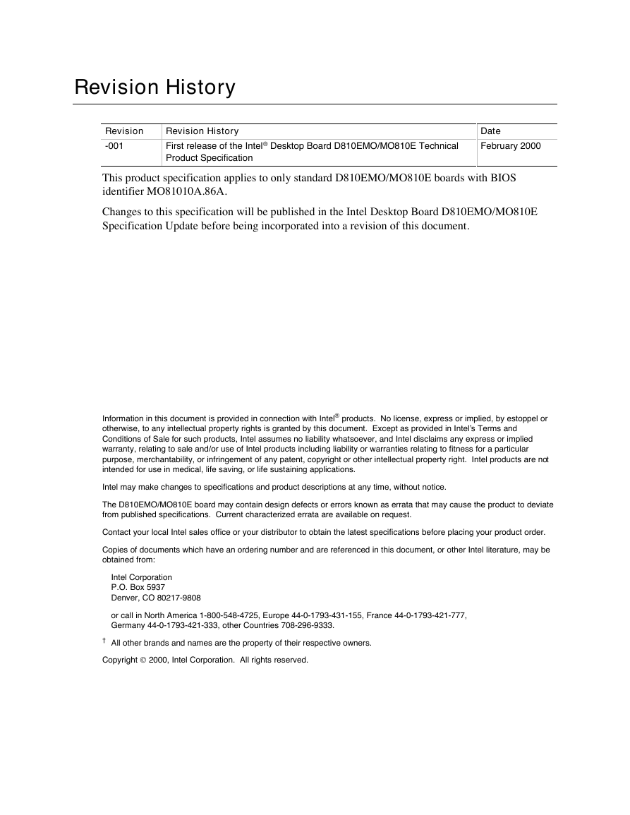
Revision History Revision -001 Revision History First release of the Intel® Desktop Board D810EMO/MO810E Technical Product Specification Date February 2000 This product specification applies to only standard D810EMO/MO810E boards with BIOS identifier MO81010A.86A. Changes to this specification will be published in the Intel Desktop Board D810EMO/MO810E Specification Update before being incorporated into a revision of this document. Information in this document is provided in connection with Intel® products. No license, express or implied, by estoppel or otherwise, to any intellectual property rights is granted by this document. Except as provided in Intel’s Terms and Conditions of Sale for such products, Intel assumes no liability whatsoever, and Intel disclaims any express or implied warranty, relating to sale and/or use of Intel products including liability or warranties relating to fitness for a particular purpose, merchantability, or infringement of any patent, copyright or other intellectual property right. Intel products are not intended for use in medical, life saving, or life sustaining applications. Intel may make changes to specifications and product descriptions at any time, without notice. The D810EMO/MO810E board may contain design defects or errors known as errata that may cause the product to deviate from published specifications. Current characterized errata are available on request. Contact your local Intel sales office or your distributor to obtain the latest specifications before placing your product order. Copies of documents which have an ordering number and are referenced in this document, or other Intel literature, may be obtained from: Intel Corporation P.O. Box 5937 Denver, CO 80217-9808 or call in North America 1-800-548-4725, Europe 44-0-1793-431-155, France 44-0-1793-421-777, Germany 44-0-1793-421-333, other Countries 708-296-9333. † All other brands and names are the property of their respective owners. Copyright 2000, Intel Corporation. All rights reserved.
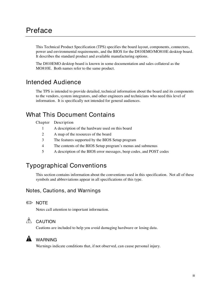
Preface This Technical Product Specification (TPS) specifies the board layout, components, connectors, power and environmental requirements, and the BIOS for the D810EMO/MO810E desktop board. It describes the standard product and available manufacturing options. The D810EMO desktop board is known in some documentation and sales collateral as the MO810E. Both names refer to the same product. Intended Audience The TPS is intended to provide detailed, technical information about the board and its components to the vendors, system integrators, and other engineers and technicians who need this level of information. It is specifically not intended for general audiences. What This Document Contains Chapter Description 1 2 3 4 5 A description of the hardware used on this board A map of the resources of the board The features supported by the BIOS Setup program The contents of the BIOS Setup program’s menus and submenus A description of the BIOS error messages, beep codes, and POST codes Typographical Conventions This section contains information about the conventions used in this specification. Not all of these symbols and abbreviations appear in all specifications of this type. Notes, Cautions, and Warnings / NOTE Notes call attention to important information. CAUTION Cautions are included to help you avoid damaging hardware or losing data. WARNING Warnings indicate conditions that, if not observed, can cause personal injury. iii
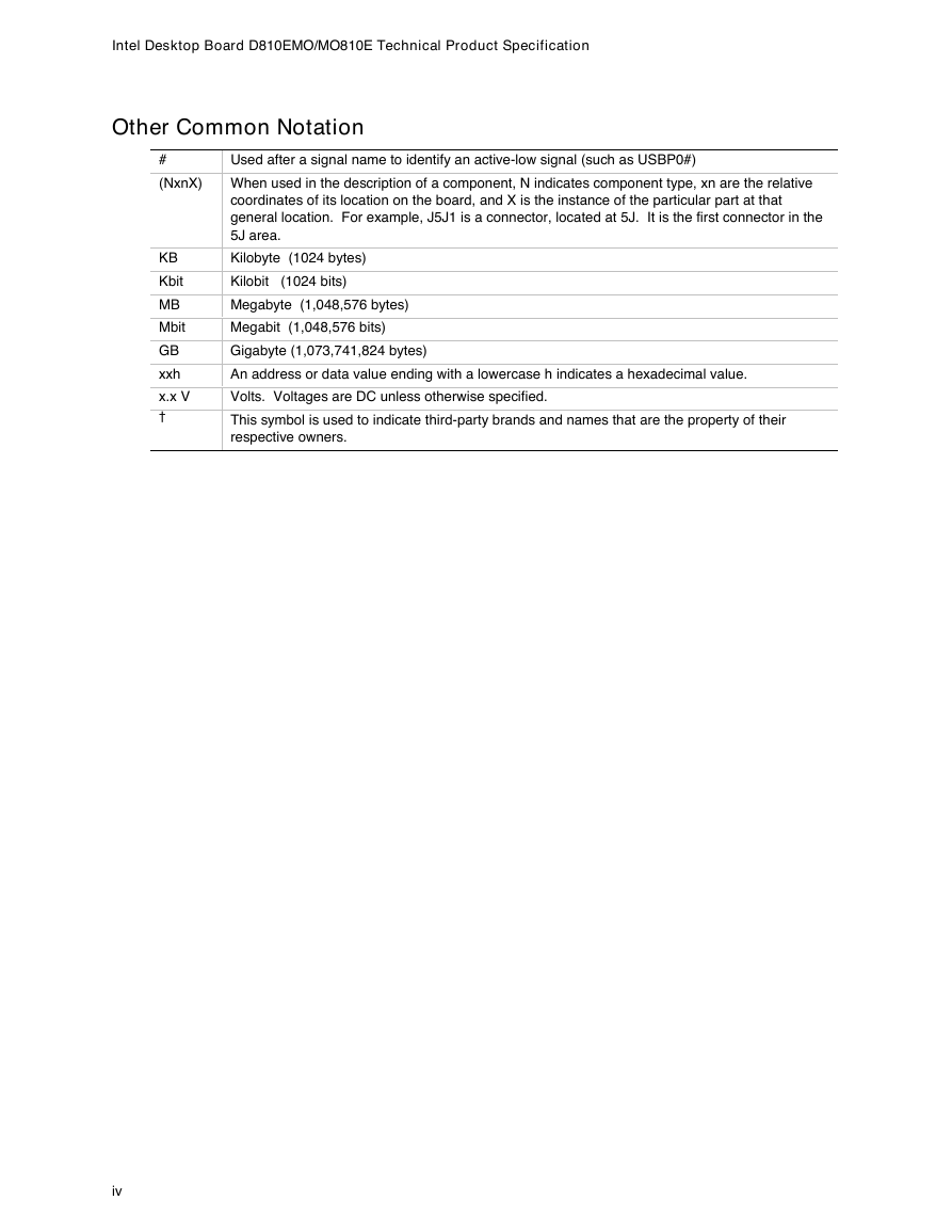
Intel Desktop Board D810EMO/MO810E Technical Product Specification Other Common Notation # (NxnX) KB Kbit MB Mbit GB xxh x.x V † Used after a signal name to identify an active-low signal (such as USBP0#) When used in the description of a component, N indicates component type, xn are the relative coordinates of its location on the board, and X is the instance of the particular part at that general location. For example, J5J1 is a connector, located at 5J. It is the first connector in the 5J area. Kilobyte (1024 bytes) Kilobit (1024 bits) Megabyte (1,048,576 bytes) Megabit (1,048,576 bits) Gigabyte (1,073,741,824 bytes) An address or data value ending with a lowercase h indicates a hexadecimal value. Volts. Voltages are DC unless otherwise specified. This symbol is used to indicate third-party brands and names that are the property of their respective owners. iv
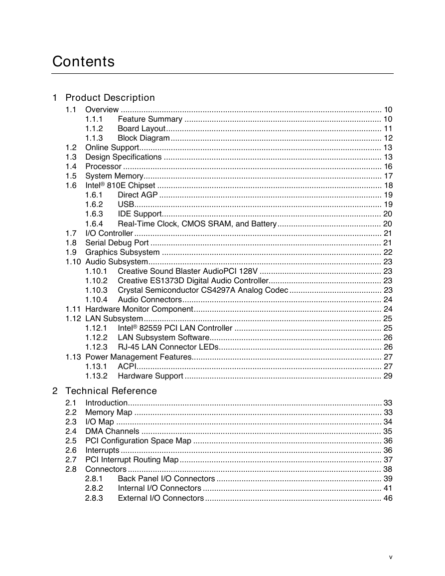
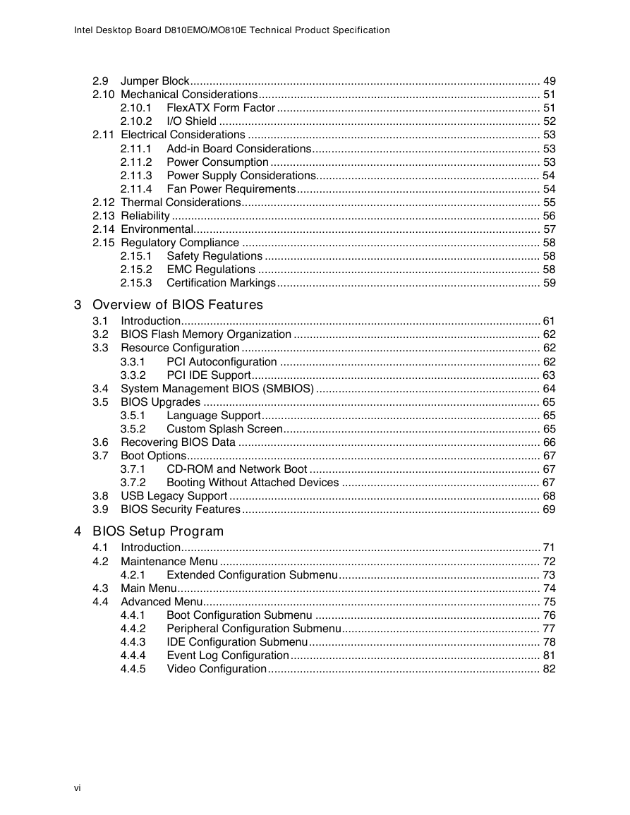
Contents 1 Product Description 1.1.1 1.1.2 1.1.3 1.6.1 1.6.2 1.6.3 1.6.4 1.1 Overview ................................................................................................................... 10 Feature Summary ....................................................................................... 10 Board Layout............................................................................................... 11 Block Diagram............................................................................................. 12 1.2 Online Support........................................................................................................... 13 1.3 Design Specifications ................................................................................................ 13 1.4 Processor .................................................................................................................. 16 1.5 System Memory......................................................................................................... 17 1.6 Intel® 810E Chipset ................................................................................................... 18 Direct AGP .................................................................................................. 19 USB............................................................................................................. 19 IDE Support................................................................................................. 20 Real-Time Clock, CMOS SRAM, and Battery.............................................. 20 1.7 I/O Controller ............................................................................................................. 21 1.8 Serial Debug Port ...................................................................................................... 21 1.9 Graphics Subsystem ................................................................................................. 22 1.10 Audio Subsystem....................................................................................................... 23 1.10.1 Creative Sound Blaster AudioPCI 128V ...................................................... 23 1.10.2 Creative ES1373D Digital Audio Controller.................................................. 23 1.10.3 Crystal Semiconductor CS4297A Analog Codec ......................................... 23 1.10.4 Audio Connectors........................................................................................ 24 1.11 Hardware Monitor Component................................................................................... 24 1.12 LAN Subsystem......................................................................................................... 25 Intel® 82559 PCI LAN Controller ................................................................. 25 1.12.1 1.12.2 LAN Subsystem Software............................................................................ 26 1.12.3 RJ-45 LAN Connector LEDs........................................................................ 26 1.13 Power Management Features.................................................................................... 27 1.13.1 ACPI............................................................................................................ 27 1.13.2 Hardware Support ....................................................................................... 29 2 Technical Reference 2.1 Introduction................................................................................................................ 33 2.2 Memory Map ............................................................................................................. 33 2.3 I/O Map ..................................................................................................................... 34 2.4 DMA Channels .......................................................................................................... 35 2.5 PCI Configuration Space Map ................................................................................... 36 2.6 Interrupts ................................................................................................................... 36 2.7 PCI Interrupt Routing Map ......................................................................................... 37 2.8 Connectors ................................................................................................................ 38 Back Panel I/O Connectors ......................................................................... 39 Internal I/O Connectors ............................................................................... 41 External I/O Connectors .............................................................................. 46 2.8.1 2.8.2 2.8.3 v
Intel Desktop Board D810EMO/MO810E Technical Product Specification 2.10.1 2.10.2 2.9 Jumper Block............................................................................................................. 49 2.10 Mechanical Considerations........................................................................................ 51 FlexATX Form Factor .................................................................................. 51 I/O Shield .................................................................................................... 52 2.11 Electrical Considerations ........................................................................................... 53 2.11.1 Add-in Board Considerations....................................................................... 53 2.11.2 Power Consumption .................................................................................... 53 2.11.3 Power Supply Considerations...................................................................... 54 2.11.4 Fan Power Requirements............................................................................ 54 2.12 Thermal Considerations............................................................................................. 55 2.13 Reliability ................................................................................................................... 56 2.14 Environmental............................................................................................................ 57 2.15 Regulatory Compliance ............................................................................................. 58 2.15.1 Safety Regulations ...................................................................................... 58 2.15.2 EMC Regulations ........................................................................................ 58 2.15.3 Certification Markings.................................................................................. 59 3 Overview of BIOS Features 3.3.1 3.3.2 3.1 Introduction................................................................................................................ 61 3.2 BIOS Flash Memory Organization ............................................................................. 62 3.3 Resource Configuration ............................................................................................. 62 PCI Autoconfiguration ................................................................................. 62 PCI IDE Support.......................................................................................... 63 3.4 System Management BIOS (SMBIOS) ...................................................................... 64 3.5 BIOS Upgrades ......................................................................................................... 65 Language Support....................................................................................... 65 Custom Splash Screen................................................................................ 65 3.6 Recovering BIOS Data .............................................................................................. 66 3.7 Boot Options.............................................................................................................. 67 CD-ROM and Network Boot ........................................................................ 67 Booting Without Attached Devices .............................................................. 67 3.8 USB Legacy Support ................................................................................................. 68 3.9 BIOS Security Features ............................................................................................. 69 3.5.1 3.5.2 3.7.1 3.7.2 4 BIOS Setup Program 4.2.1 4.1 Introduction................................................................................................................ 71 4.2 Maintenance Menu .................................................................................................... 72 Extended Configuration Submenu............................................................... 73 4.3 Main Menu................................................................................................................. 74 4.4 Advanced Menu......................................................................................................... 75 Boot Configuration Submenu ...................................................................... 76 Peripheral Configuration Submenu.............................................................. 77 IDE Configuration Submenu........................................................................ 78 Event Log Configuration.............................................................................. 81 Video Configuration..................................................................................... 82 4.4.1 4.4.2 4.4.3 4.4.4 4.4.5 vi
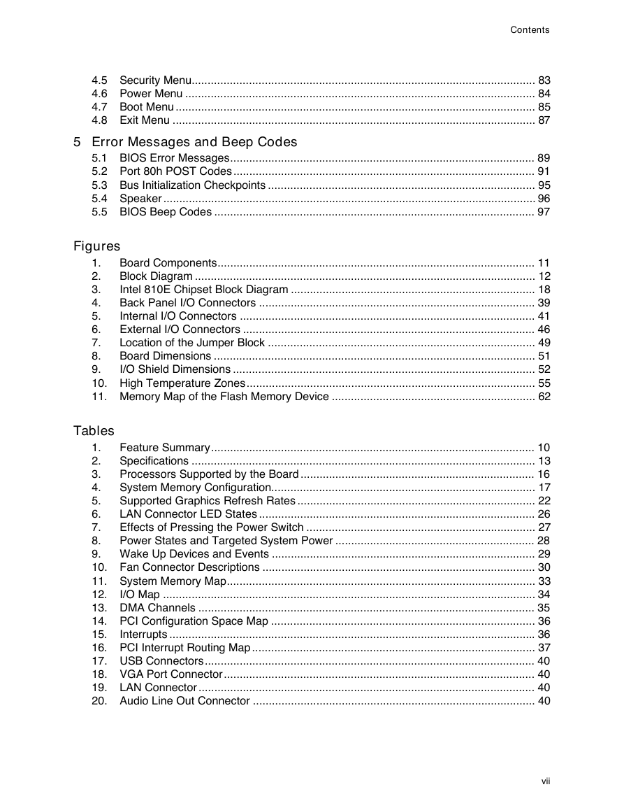
Contents 4.5 Security Menu............................................................................................................ 83 4.6 Power Menu .............................................................................................................. 84 4.7 Boot Menu ................................................................................................................. 85 4.8 Exit Menu .................................................................................................................. 87 5 Error Messages and Beep Codes 5.1 BIOS Error Messages................................................................................................ 89 5.2 Port 80h POST Codes ............................................................................................... 91 5.3 Bus Initialization Checkpoints .................................................................................... 95 5.4 Speaker ..................................................................................................................... 96 5.5 BIOS Beep Codes ..................................................................................................... 97 Figures Board Components.................................................................................................... 11 1. Block Diagram ........................................................................................................... 12 2. Intel 810E Chipset Block Diagram ............................................................................. 18 3. Back Panel I/O Connectors ....................................................................................... 39 4. Internal I/O Connectors ............................................................................................. 41 5. External I/O Connectors ............................................................................................ 46 6. Location of the Jumper Block .................................................................................... 49 7. Board Dimensions ..................................................................................................... 51 8. 9. I/O Shield Dimensions ............................................................................................... 52 10. High Temperature Zones........................................................................................... 55 11. Memory Map of the Flash Memory Device ................................................................ 62 Tables 1. Feature Summary...................................................................................................... 10 2. Specifications ............................................................................................................ 13 3. Processors Supported by the Board .......................................................................... 16 4. System Memory Configuration................................................................................... 17 5. Supported Graphics Refresh Rates ........................................................................... 22 6. LAN Connector LED States ....................................................................................... 26 7. Effects of Pressing the Power Switch ........................................................................ 27 8. Power States and Targeted System Power ............................................................... 28 9. Wake Up Devices and Events ................................................................................... 29 10. Fan Connector Descriptions ...................................................................................... 30 11. System Memory Map................................................................................................. 33 12. I/O Map ..................................................................................................................... 34 13. DMA Channels .......................................................................................................... 35 14. PCI Configuration Space Map ................................................................................... 36 15. Interrupts ................................................................................................................... 36 16. PCI Interrupt Routing Map ......................................................................................... 37 17. USB Connectors........................................................................................................ 40 18. VGA Port Connector.................................................................................................. 40 19. LAN Connector .......................................................................................................... 40 20. Audio Line Out Connector ......................................................................................... 40 vii
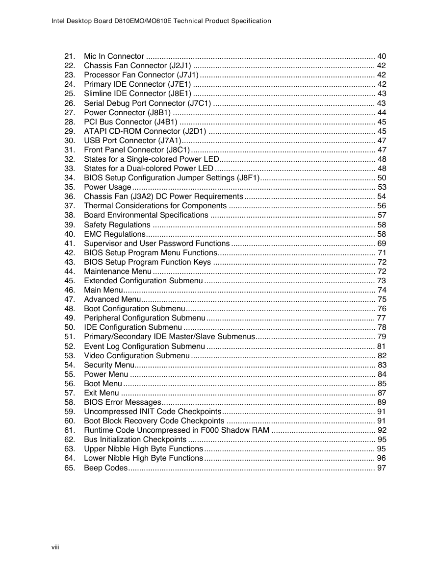
Intel Desktop Board D810EMO/MO810E Technical Product Specification 21. Mic In Connector ....................................................................................................... 40 22. Chassis Fan Connector (J2J1) .................................................................................. 42 23. Processor Fan Connector (J7J1) ............................................................................... 42 24. Primary IDE Connector (J7E1) .................................................................................. 42 25. Slimline IDE Connector (J8E1) .................................................................................. 43 26. Serial Debug Port Connector (J7C1) ......................................................................... 43 27. Power Connector (J8B1) ........................................................................................... 44 28. PCI Bus Connector (J4B1) ........................................................................................ 45 29. ATAPI CD-ROM Connector (J2D1) ........................................................................... 45 30. USB Port Connector (J7A1)....................................................................................... 47 31. Front Panel Connector (J8C1) ................................................................................... 47 32. States for a Single-colored Power LED...................................................................... 48 33. States for a Dual-colored Power LED ........................................................................ 48 34. BIOS Setup Configuration Jumper Settings (J8F1).................................................... 50 35. Power Usage ............................................................................................................. 53 36. Chassis Fan (J3A2) DC Power Requirements ........................................................... 54 37. Thermal Considerations for Components .................................................................. 56 38. Board Environmental Specifications .......................................................................... 57 39. Safety Regulations .................................................................................................... 58 40. EMC Regulations....................................................................................................... 58 41. Supervisor and User Password Functions ................................................................. 69 42. BIOS Setup Program Menu Functions....................................................................... 71 43. BIOS Setup Program Function Keys ......................................................................... 72 44. Maintenance Menu .................................................................................................... 72 45. Extended Configuration Submenu ............................................................................. 73 46. Main Menu................................................................................................................. 74 47. Advanced Menu......................................................................................................... 75 48. Boot Configuration Submenu..................................................................................... 76 49. Peripheral Configuration Submenu ............................................................................ 77 50. IDE Configuration Submenu ...................................................................................... 78 51. Primary/Secondary IDE Master/Slave Submenus...................................................... 79 52. Event Log Configuration Submenu ............................................................................ 81 53. Video Configuration Submenu ................................................................................... 82 54. Security Menu............................................................................................................ 83 55. Power Menu .............................................................................................................. 84 56. Boot Menu ................................................................................................................. 85 57. Exit Menu .................................................................................................................. 87 58. BIOS Error Messages................................................................................................ 89 59. Uncompressed INIT Code Checkpoints..................................................................... 91 60. Boot Block Recovery Code Checkpoints ................................................................... 91 61. Runtime Code Uncompressed in F000 Shadow RAM ............................................... 92 62. Bus Initialization Checkpoints .................................................................................... 95 63. Upper Nibble High Byte Functions ............................................................................. 95 64. Lower Nibble High Byte Functions ............................................................................. 96 65. Beep Codes............................................................................................................... 97 viii
分享到:
收藏