ELM327
OBD to RS232 Interpreter
Description
Features
Almost all of the automobiles produced today
are required, by law, to provide an interface for the
connection of diagnostic test equipment. The data
transfer on these interfaces follow several standards,
but none of them are directly usable by PCs or smart
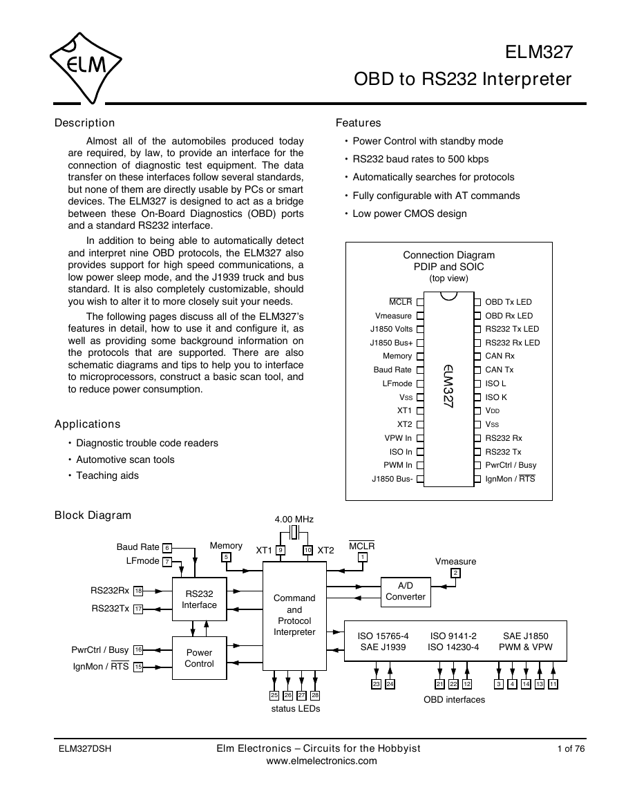
devices. The ELM327 is designed to act as a bridge
between these On-Board Diagnostics (OBD) ports
and a standard RS232 interface.
In addition to being able to automatically detect
and interpret nine OBD protocols, the ELM327 also
provides support for high speed communications, a
low power sleep mode, and the J1939 truck and bus
standard. It is also completely customizable, should
you wish to alter it to more closely suit your needs.
The following pages discuss all of the ELM327’s
features in detail, how to use it and configure it, as
well as providing some background information on
the protocols that are supported. There are also
schematic diagrams and tips to help you to interface
to microprocessors, construct a basic scan tool, and
to reduce power consumption.
Applications
• Diagnostic trouble code readers
• Automotive scan tools
• Teaching aids
• Power Control with standby mode
• RS232 baud rates to 500 kbps
• Automatically searches for protocols
• Fully configurable with AT commands
• Low power CMOS design
Connection Diagram
PDIP and SOIC
(top view)
MCLR
Vmeasure
J1850 Volts
J1850 Bus+
Memory
Baud Rate
LFmode
VSS
XT1
XT2
VPW In
ISO In
PWM In
J1850 Bus-
OBD Tx LED
OBD Rx LED
RS232 Tx LED
RS232 Rx LED
CAN Rx
CAN Tx
ISO L
ISO K
VDD
VSS
RS232 Rx
RS232 Tx
PwrCtrl / Busy
IgnMon / RTS
Block Diagram
4.00 MHz
Baud Rate
LFmode
6
7
Memory
5
XT1
9
10
XT2 MCLR
1
RS232Rx
RS232Tx
PwrCtrl / Busy
IgnMon / RTS
18
17
16
15
RS232
Interface
Power
Control
Command
and
Protocol
Interpreter
27
26
28
25
status LEDs
Vmeasure
2
A/D
Converter
ISO 15765-4
SAE J1939
ISO 9141-2
ISO 14230-4
SAE J1850
PWM & VPW
23
24
21
22
12
3
4
14
13
11
OBD interfaces
ELM327DSH
Elm Electronics – Circuits for the Hobbyist
www.elmelectronics.com
1 of 76
�
Contents
Electrical Information
Using the ELM327
Advanced Features
ELM327
Pin Descriptions........................................................................... 3
Unused Pins.................................................................................5
Ordering Information.................................................................... 5
Absolute Maximum Ratings......................................................... 5
Electrical Characteristics..............................................................6
Overview...................................................................................... 7
Communicating with the ELM327................................................ 7
AT Commands............................................................................. 9
AT Command Summary...............................................................9
AT Command Descriptions........................................................ 11
Reading the Battery Voltage...................................................... 27
OBD Commands........................................................................ 28
Talking to the Vehicle.................................................................29
Interpreting Trouble Codes........................................................ 31
Resetting Trouble Codes........................................................... 32
Quick Guide for Reading Trouble Codes................................... 32
Bus Initiation...............................................................................33
Wakeup Messages.....................................................................33
Selecting Protocols.................................................................... 34
OBD Message Formats..............................................................35
Setting the Headers................................................................... 37
Monitoring the Bus..................................................................... 40
CAN Messages and Filtering..................................................... 41
Multiline Responses................................................................... 42
CAN Message Formats..............................................................44
Restoring Order..........................................................................45
Altering Flow Control Messages................................................ 46
Using CAN Extended Addresses............................................... 47
SAE J1939 Messages................................................................48
Using J1939............................................................................... 50
The FMS Standard.....................................................................53
Programmable Parameters........................................................ 54
Programmable Parameter Summary......................................... 55
Using Higher RS232 Baud Rates...............................................59
Setting Timeouts - AT ST and AT AT Commands..................... 61
Power Control............................................................................ 62
Design Examples
Microprocessor Interfaces..........................................................64
Example Applications.................................................................65
Modifications for Low Power Standby Operation....................... 70
Misc.
Error Messages and Alerts.........................................................72
Outline Diagrams....................................................................... 74
Copyright and Disclaimer........................................................... 74
Index.......................................................................................... 75
ELM327DSH
Elm Electronics – Circuits for the Hobbyist
www.elmelectronics.com
2 of 76
�
Pin Descriptions
MCLR (pin 1)
A momentary (>2µsec) logic low applied to this input
will reset the ELM327. If unused, this pin should be
connected to a logic high (VDD) level.
Vmeasure (pin 2)
This analog input is used to measure a 0 to 5V
signal that is applied to it. Care must be taken to
prevent the voltage from going outside of the supply
levels of the ELM327, or damage may occur. If it is
not used, this pin should be tied to either VDD or VSS.
J1850 Volts (pin 3)
This output can be used to control a voltage supply
for the J1850 Bus+ output. The pin normally outputs
a logic high level when a nominal 8V is required (for
J1850 VPW), and a low level for 5V (for J1850
PWM), but this can be changed with PP 12. If this
switching capability
for your
application, this output can be left open-circuited.
required
is not
J1850 Bus+ (pin 4)
is used
This active high output
the
J1850 Bus+ Line to an active level. Note that this
signal does not have to be used for the Bus- Line (as
was the case for the ELM320), since a separate
J1850 Bus- drive output is provided on pin 14.
to drive
Memory (pin 5)
ELM327
return and a linefeed character. If it is at a low level,
lines will be terminated by a carriage return only.
This behaviour can always be modified by issuing an
AT L1 or AT L0 command.
VSS (pin 8)
Circuit common must be connected to this pin.
XT1 (pin 9) and XT2 (pin 10)
A 4.000 MHz oscillator crystal is connected between
these two pins. Loading capacitors as required by
the crystal (typically 27pF each) will also need to be
connected between each of these pins and circuit
common (Vss).
Note that this device has not been configured for
operation with an external oscillator – it expects a
crystal to be connected to these pins. Use of an
external clock source is not recommended. Also,
note that this oscillator is turned off when in the Low
Power or ‘standby’ mode of operation.
VPW In (pin 11)
This is the active high input for the J1850 VPW data
signal. When at rest (bus recessive) this pin should
be at a low logic level. This input has Schmitt trigger
wave shaping, so no special amplification
is
required.
This input controls the default state of the memory
option. If this pin is at a high level during power-up or
reset, the memory function will be enabled by
default. If it is at a low level, then the default will be
to have it disabled. Memory can always be enabled
or disabled with the AT M1 and AT M0 commands.
ISO In (pin 12)
This is the active low input for the ISO 9141 and
ISO 14230 data signal. It is derived from the K Line,
and should be at a high logic level when at rest (bus
recessive). No special amplification is required, as
this input has Schmitt trigger wave shaping.
Baud Rate (pin 6)
PWM In (pin 13)
This input controls the baud rate of the RS232
interface. If it is at a high level during power-up or
reset, the baud rate will be set to 38400 (or the rate
that has been set by PP 0C). If at a low level, the
baud rate will always be 9600.
This is the active low input for the J1850 PWM data
signal. It should normally be at a high level when at
rest (ie. bus recessive). This input has Schmitt
trigger wave shaping, so no special amplification is
required.
LFmode (pin 7)
J1850 Bus- (pin 14)
This input is used to select the default linefeed mode
to be used after a power-up or system reset. If it is at
a high level, then by default messages sent by the
ELM327 will be terminated with both a carriage
This active high output is used to drive the J1850
Bus- Line to an active (dominant) level for J1850
PWM applications. If unused, this output can be left
open-circuited.
ELM327DSH
Elm Electronics – Circuits for the Hobbyist
www.elmelectronics.com
3 of 76
�
Pin Descriptions (continued)
IgnMon / RTS (pin 15)
ignition were
turned off. An
This input pin can serve one of two functions,
depending on how
the Power Control options
(PP 0E) are set.
If both bit 7 and bit 2 of PP 0E are ‘1’s, this pin will
act as an Ignition Monitor. This will result in a switch
to the Low Power mode of operation, should the
signal go to a low level, as would happen if the
vehicle’s
internal
‘debounce’ timer is used to ensure that the ELM327
does not shut down for noise at the input.
When the voltage at pin 15 is again restored to a
high level, and a time of 1 or 5 seconds (as set by
PP 0E bit 1) passes, the ELM327 will perform a
‘Warm Start’ and return to normal operation. A low to
high transition at pin 15 will in fact restore normal
operation, regardless of the setting of PP 0E bit 2, or
whether pin 15 was the initial cause for the low
power mode. This feature allows a system to control
how and when it switches to low power standby
operation, but still have automatic wakeup by the
ignition voltage, or even by a pushbutton.
If either bit 7 or bit 2 of PP 0E are ‘0’, this pin will
function as an active low ‘Request To Send’ input.
This can be used to interrupt the OBD processing in
order to send a new command, or as previously
mentioned, to highlight the fact that the ignition has
been turned off. Normally kept at a high level, this
input is brought low for attention, and should remain
so until the Busy line (pin 16) indicates that the
ELM327 is no longer busy, or until a prompt
character is received (if pin 16 is being used for
power control).
This input has Schmitt trigger wave shaping. By
default, pin 15 acts as the RTS interrupt input.
PwrCtrl / Busy (pin 16)
This output pin can serve one of two functions,
depending on how
the Power Control options
(PP 0E) are set.
If bit 7 of PP 0E is a ‘1’ (the default), this pin will
function as a Power Control output. The normal state
of the pin will be as set by PP 0E bit 6, and the pin
will remain in that state until the ELM327 switches to
the Low Power mode of operation, when the output
changes to the opposite level. This output is typically
used to control enable inputs, but may also be used
for relay circuits, etc. with suitable buffering. The
ELM327
discussion on page 70 (‘Modifications for Low Power
Standby Operation’) provides more detail on how to
use this output.
If bit 7 of PP 0E is a ‘0’, pin 16 will function as a
‘Busy’ output, showing when the ELM327 is actively
processing a command (the output will be at a high
level), or when it is idle, ready to receive commands
(the output will be low).
By default, bit 7 of PP 0E is ‘1’, so pin 16 provides
the Power Control function.
RS232Tx (pin 17)
This is the RS232 data transmit output. The signal
level is compatible with most interface ICs (the
output is high when idle), and there is sufficient
current drive to allow interfacing using only a PNP
transistor, if desired.
RS232Rx (pin 18)
This is the RS232 receive data input. The signal
level is compatible with most interface ICs (when at
idle, the level should be high), but can be used with
other interfaces as well, since the input has Schmitt
trigger wave shaping.
VSS (pin 19)
Circuit common must be connected to this pin.
VDD (pin 20)
This pin is the positive supply pin, and should always
be the most positive point in the circuit. Internal
circuitry connected to this pin is used to provide
power on reset of the microprocessor, so an external
reset signal is not required. Refer to the Electrical
Characteristics section for further information.
ISO K (pin 21) and ISO L (pin 22)
These are the active high output signals which are
used to drive the ISO 9141 and ISO 14230 buses to
an active (dominant) level. Many new vehicles do not
require the L Line – if yours does not, you can simply
leave pin 22 open-circuited.
CAN Tx (pin 23) and CAN Rx (pin 24)
These are the two CAN interface signals that must
be connected to a CAN transceiver IC (see the
Example Applications section for more information).
ELM327DSH
Elm Electronics – Circuits for the Hobbyist
www.elmelectronics.com
4 of 76
�
ELM327
Pin Descriptions (continued)
If unused, pin 24 must be connected to a logic high
(VDD) level.
RS232 Rx LED (pin 25), RS232 Tx LED (pin 26),
OBD Rx LED (pin 27) and OBD Tx LED (pin 28)
These four output pins are normally high, and are
driven to low levels when the ELM327 is transmitting
or receiving data. These outputs are suitable for
directly driving most LEDs through current limiting
resistors, or interfacing to other logic circuits. If
unused, these pins may be left open-circuited.
Note that pin 28 can also be used to turn off all of the
Programmable Parameters, if you can not do so by
using the normal interface - see pages 54 and 55 for
more details.
Unused Pins
When people only want to implement a portion of what the ELM327 is capable of, they often ask what to do with the
unused pins. The rule is that unused outputs may be left open-circuited with nothing connected to them, but unused
inputs must be terminated. The ELM327 is a CMOS integrated circuit that can not have any inputs left floating (or
you might damage the IC). Connect unused inputs as follows:
Pin
Level
1
H
2
H*
5
H*
6
H*
7
H*
11
H*
12
L*
13
L*
15
H
18
H
24
H
Note that the inputs that are shown with an asterisk (*) may be connected to either a High (VDD) or a Low (VSS)
level, but the level shown is preferred.
Ordering Information
These integrated circuits are 28 pin devices, available in either a 300 mil wide plastic (‘skinny’) DIP format or in a
300 mil (7.50 mm body) SOIC surface mount type of package. We do not offer an option for QFN packages.
To order, add the appropriate suffix to the part number:
300 mil 28 pin Plastic DIP..............................ELM327P
300 mil 28 pin SOIC....................................ELM327SM
Absolute Maximum Ratings
Storage Temperature....................... -65°C to +150°C
Ambient Temperature with
Power Applied....................................-40°C to +85°C
Voltage on VDD with respect to VSS..... -0.3V to +7.5V
Voltage on any other pin with
respect to VSS........................... -0.3V to (VDD + 0.3V)
Note:
These values are given as a design guideline only.
The ability to operate to these levels is neither
inferred nor recommended, and stresses beyond
those listed here will likely damage the device.
ELM327DSH
Elm Electronics – Circuits for the Hobbyist
www.elmelectronics.com
5 of 76
�
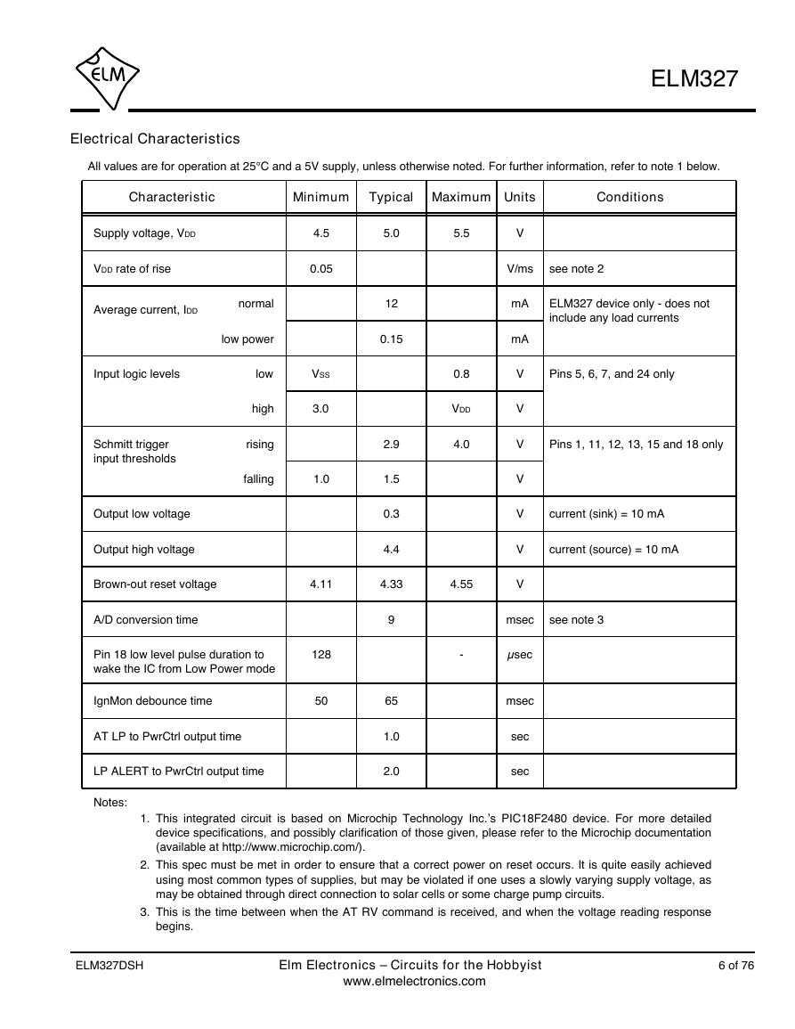
Electrical Characteristics
All values are for operation at 25°C and a 5V supply, unless otherwise noted. For further information, refer to note 1 below.
Characteristic
Minimum Typical Maximum
Units
Conditions
ELM327
4.5
0.05
VSS
3.0
normal
low power
low
high
rising
falling
1.0
Supply voltage, VDD
VDD rate of rise
Average current, IDD
Input logic levels
Schmitt trigger
input thresholds
Output low voltage
Output high voltage
5.0
5.5
V
V/ms
see note 2
0.8
VDD
4.0
12
0.15
2.9
1.5
0.3
4.4
ELM327 device only - does not
include any load currents
Pins 5, 6, 7, and 24 only
Pins 1, 11, 12, 13, 15 and 18 only
current (sink) = 10 mA
current (source) = 10 mA
mA
mA
V
V
V
V
V
V
V
Brown-out reset voltage
4.11
4.33
4.55
A/D conversion time
Pin 18 low level pulse duration to
wake the IC from Low Power mode
IgnMon debounce time
AT LP to PwrCtrl output time
LP ALERT to PwrCtrl output time
Notes:
128
50
9
65
1.0
2.0
msec
see note 3
-
µsec
msec
sec
sec
1. This integrated circuit is based on Microchip Technology Inc.’s PIC18F2480 device. For more detailed
device specifications, and possibly clarification of those given, please refer to the Microchip documentation
(available at http://www.microchip.com/).
2. This spec must be met in order to ensure that a correct power on reset occurs. It is quite easily achieved
using most common types of supplies, but may be violated if one uses a slowly varying supply voltage, as
may be obtained through direct connection to solar cells or some charge pump circuits.
3. This is the time between when the AT RV command is received, and when the voltage reading response
begins.
ELM327DSH
Elm Electronics – Circuits for the Hobbyist
www.elmelectronics.com
6 of 76
�
ELM327
Overview
The following describes how to use the ELM327 to
features of this product as well.
obtain information from your vehicle.
We begin by discussing just how to ‘talk’ to the IC
using a PC, then explain how to change options using
‘AT’ commands, and finally we show how to use the
ELM327 to obtain trouble codes (and reset them). For
the more advanced experimenters, there are also
sections on how to use some of the programmable
Using the ELM327 is not as daunting as it first
seems. Many users will never need to issue an ‘AT’
command, adjust timeouts, or change the headers. For
most, all that is required is a PC or smart device with a
terminal program (such as HyperTerminal or ZTerm),
and a little knowledge of OBD commands, which we
will provide in the following sections…
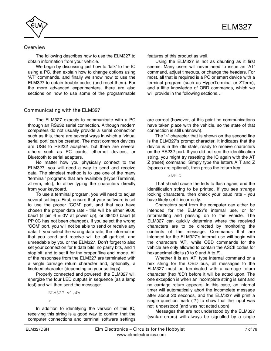
Communicating with the ELM327
The ELM327 expects to communicate with a PC
through an RS232 serial connection. Although modern
computers do not usually provide a serial connection
such as this, there are several ways in which a ‘virtual
serial port’ can be created. The most common devices
are USB to RS232 adapters, but there are several
others such as PC cards, ethernet devices, or
Bluetooth to serial adapters.
No matter how you physically connect to the
ELM327, you will need a way to send and receive
data. The simplest method is to use one of the many
‘terminal’ programs that are available (HyperTerminal,
ZTerm, etc.), to allow typing the characters directly
from your keyboard.
To use a terminal program, you will need to adjust
several settings. First, ensure that your software is set
to use the proper ‘COM’ port, and that you have
chosen the proper data rate - this will be either 9600
baud (if pin 6 = 0V at power up), or 38400 baud (if
PP 0C has not been changed). If you select the wrong
‘COM’ port, you will not be able to send or receive any
data. If you select the wrong data rate, the information
that you send and receive will be all garbled, and
unreadable by you or the ELM327. Don’t forget to also
set your connection for 8 data bits, no parity bits, and 1
stop bit, and to set it for the proper ‘line end’ mode. All
of the responses from the ELM327 are terminated with
a single carriage return character and, optionally, a
linefeed character (depending on your settings).
Properly connected and powered, the ELM327 will
energize the four LED outputs in sequence (as a lamp
test) and will then send the message:
ELM327 v1.4b
>
In addition to identifying the version of this IC,
receiving this string is a good way to confirm that the
computer connections and terminal software settings
are correct (however, at this point no communications
have taken place with the vehicle, so the state of that
connection is still unknown).
The ‘>’ character that is shown on the second line
is the ELM327’s prompt character. It indicates that the
device is in the idle state, ready to receive characters
on the RS232 port. If you did not see the identification
string, you might try resetting the IC again with the AT
Z (reset) command. Simply type the letters A T and Z
(spaces are optional), then press the return key:
>AT Z
That should cause the leds to flash again, and the
identification string to be printed. If you see strange
looking characters, then check your baud rate - you
have likely set it incorrectly.
the ELM327’s
internal use, or
for
Characters sent from the computer can either be
for
intended
reformatting and passing on to the vehicle. The
ELM327 can quickly determine where the received
characters are to be directed by monitoring the
contents of
that are
intended for the ELM327’s internal use will begin with
the characters ‘AT’, while OBD commands for the
vehicle are only allowed to contain the ASCII codes for
hexadecimal digits (0 to 9 and A to F).
the message. Commands
Whether it is an ‘AT’ type internal command or a
hex string for the OBD bus, all messages to the
ELM327 must be terminated with a carriage return
character (hex ‘0D’) before it will be acted upon. The
one exception is when an incomplete string is sent and
no carriage return appears. In this case, an internal
timer will automatically abort the incomplete message
after about 20 seconds, and the ELM327 will print a
single question mark (‘?’) to show that the input was
not understood (and was not acted upon).
Messages that are not understood by the ELM327
(syntax errors) will always be signalled by a single
ELM327DSH
Elm Electronics – Circuits for the Hobbyist
www.elmelectronics.com
7 of 76
�
ELM327
commands may be entered as you prefer, as no one
method is faster or better. The ELM327 also ignores
space characters and all control characters (tab, etc.),
so they can be inserted anywhere in the input if that
improves readability.
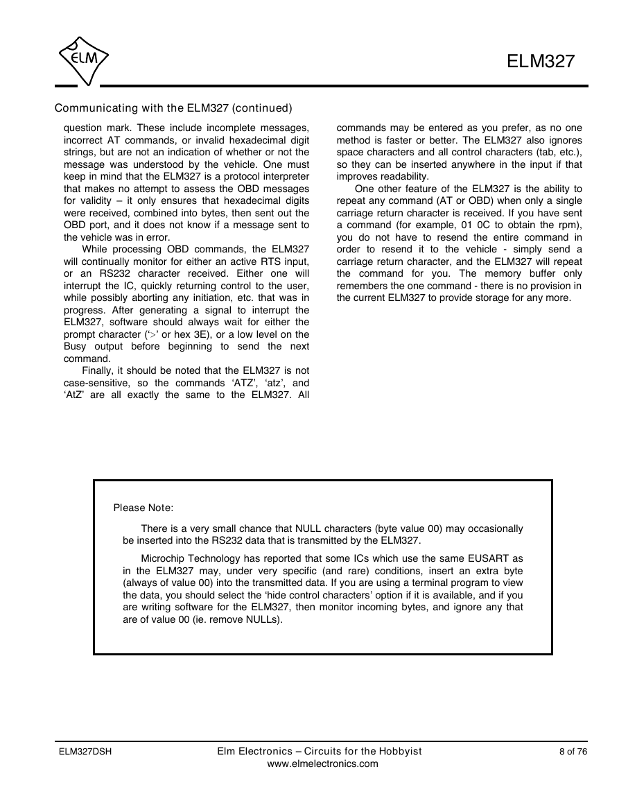
One other feature of the ELM327 is the ability to
repeat any command (AT or OBD) when only a single
carriage return character is received. If you have sent
a command (for example, 01 0C to obtain the rpm),
you do not have to resend the entire command in
order to resend it to the vehicle - simply send a
carriage return character, and the ELM327 will repeat
the command for you. The memory buffer only
remembers the one command - there is no provision in
the current ELM327 to provide storage for any more.
Communicating with the ELM327 (continued)
question mark. These include incomplete messages,
incorrect AT commands, or invalid hexadecimal digit
strings, but are not an indication of whether or not the
message was understood by the vehicle. One must
keep in mind that the ELM327 is a protocol interpreter
that makes no attempt to assess the OBD messages
for validity – it only ensures that hexadecimal digits
were received, combined into bytes, then sent out the
OBD port, and it does not know if a message sent to
the vehicle was in error.
While processing OBD commands, the ELM327
will continually monitor for either an active RTS input,
or an RS232 character received. Either one will
interrupt the IC, quickly returning control to the user,
while possibly aborting any initiation, etc. that was in
progress. After generating a signal to interrupt the
ELM327, software should always wait for either the
prompt character (‘>’ or hex 3E), or a low level on the
Busy output before beginning
the next
command.
to send
Finally, it should be noted that the ELM327 is not
case-sensitive, so the commands ‘ATZ’, ‘atz’, and
‘AtZ’ are all exactly the same to the ELM327. All
Please Note:
There is a very small chance that NULL characters (byte value 00) may occasionally
be inserted into the RS232 data that is transmitted by the ELM327.
Microchip Technology has reported that some ICs which use the same EUSART as
in the ELM327 may, under very specific (and rare) conditions, insert an extra byte
(always of value 00) into the transmitted data. If you are using a terminal program to view
the data, you should select the ‘hide control characters’ option if it is available, and if you
are writing software for the ELM327, then monitor incoming bytes, and ignore any that
are of value 00 (ie. remove NULLs).
ELM327DSH
Elm Electronics – Circuits for the Hobbyist
www.elmelectronics.com
8 of 76
�


 2023年江西萍乡中考道德与法治真题及答案.doc
 2012年重庆南川中考生物真题及答案.doc
 2013年江西师范大学地理学综合及文艺理论基础考研真题.doc
 2020年四川甘孜小升初语文真题及答案I卷.doc
 2020年注册岩土工程师专业基础考试真题及答案.doc
 2023-2024学年福建省厦门市九年级上学期数学月考试题及答案.doc
 2021-2022学年辽宁省沈阳市大东区九年级上学期语文期末试题及答案.doc
 2022-2023学年北京东城区初三第一学期物理期末试卷及答案.doc
 2018上半年江西教师资格初中地理学科知识与教学能力真题及答案.doc
 2012年河北国家公务员申论考试真题及答案-省级.doc
 2020-2021学年江苏省扬州市江都区邵樊片九年级上学期数学第一次质量检测试题及答案.doc
 2022下半年黑龙江教师资格证中学综合素质真题及答案.doc