logo资料库

IMX377CQT.pdf

第1页 / 共97页
第2页 / 共97页
第3页 / 共97页
第4页 / 共97页
第5页 / 共97页
第6页 / 共97页
第7页 / 共97页
第8页 / 共97页
资料共97页,剩余部分请下载后查看
Description
Features
Device Structure
Optical Black Array and Readout Scan Direction
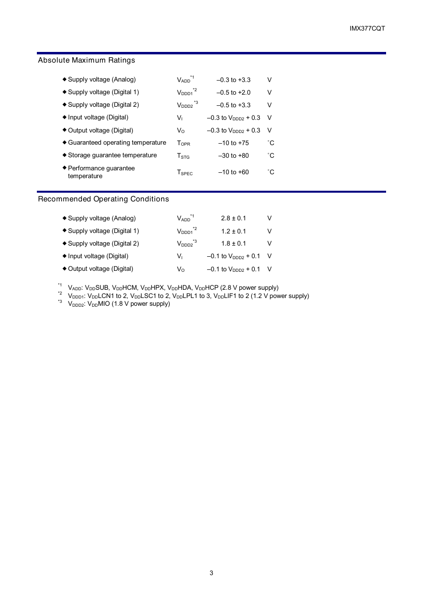
Absolute Maximum Ratings
Recommended Operating Conditions
USE RESTRICTION NOTICE
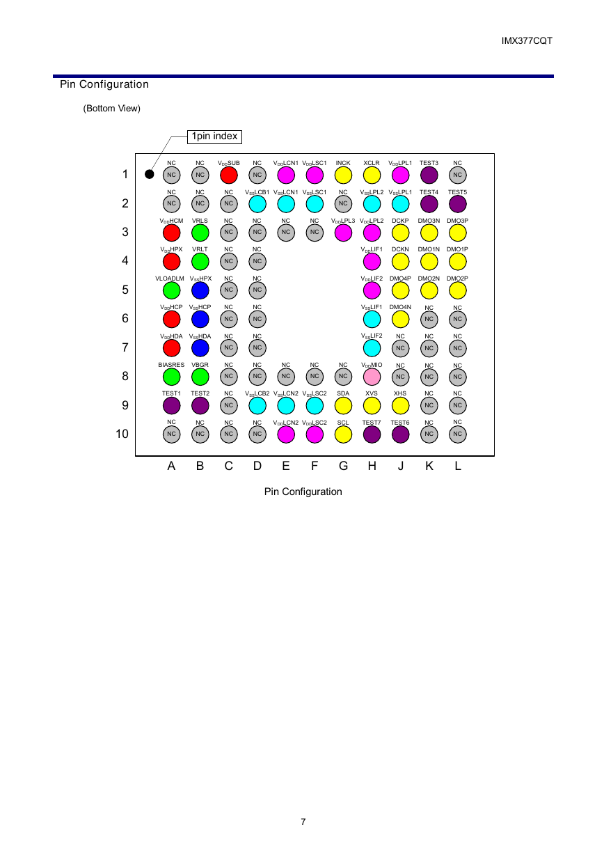
Pin Configuration
Pin Description
Electrical Characteristics
1. DC Characteristics
2. AC Characteristics
I/O Equivalent Circuit Diagram
Spectral Sensitivity Characteristics
Image Sensor Characteristics
1. Zone Definition of Image Sensor Characteristics
Image Sensor Characteristics Measurement Method
1. Measurement Conditions
2. Color Coding of this Image Sensor and Readout
3. Definition of Standard Imaging Conditions
Setting Registers Using I2C Communication
Description of Setting Registers
Pin Connection of Serial Communication Operation Specifications
Register Communication Timing
I2C Communication Protocol
Register Write and Read
Register Map
1. Register Value Reflection Timing to Output Data
2. Description of Register
3. Register Setting for Each Readout Drive Mode
3-1. When Using Type 1/2.3 Approx. 12.35 M Pixels (4:3)
3-2. When Using Type 1/2.5 Approx. 9.03 M Pixels (Approx. 17:9)
Readout Drive Modes
1. Readout Drive Modes
1-1. When Using Type 1/2.3 Approx. 12.35 M Pixels (4:3)
1-2. When Using Type 1/2.5 Approx. 9.03 M Pixels (Approx. 17:9)
1-3. Relationship between Arithmetic Processing and the Number of Output Bits in Each Readout Drive Mode
2. Image Data Output Format (CSI-2)
Frame Format
Frame Structure
Embedded Data Line
CSI-2 serial Output Setting
MIPI Transmitter
3. Detailed Specification of Each Mode
3-1. When Using Type 1/2.3 Approx. 12.35 M Pixels (4:3)
(1) Horizontal/Vertical Operation Period in Each Readout Drive Mode
(2) NTSC/PAL Compatible Drive
(3) Image Data Output Format
3-2. When Using Type 1/2.5 Approx. 9.03 M Pixels (Approx. 17:9)
(1) Horizontal/Vertical Operation Period in Each Readout Drive Mode
(2) NTSC/PAL Compatible Drive
(3) Image Data Output Format
3-3. Vertical Arbitrary Cropping Function
3-4. Horizontal Arbitrary Cropping Function
Integration Time in Each Readout Drive Mode and Mode Changes
1. Integration Time in Each Readout Drive Mode
2. Operation when Changing the Readout Drive Mode
Power-on/off Sequence
1. Power-on Sequence
2. Slew Rate Limitation of Power-on Sequence
3. Power-off Sequence
Standby Cancel Sequence
Peripheral Circuit Diagram
Notes On Handling
Package Outline
Relation between Image Height and target CRA
List of Trademark Logos and Definition Statements
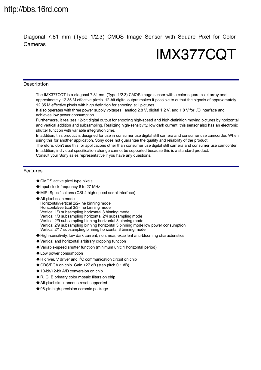
http://bbs.16rd.com Diagonal 7.81 mm (Type 1/2.3) CMOS Image Sensor with Square Pixel for Color Cameras Description IMX377CQT The IMX377CQT is a diagonal 7.81 mm (Type 1/2.3) CMOS image sensor with a color square pixel array and approximately 12.35 M effective pixels. 12-bit digital output makes it possible to output the signals of approximately 12.35 M effective pixels with high definition for shooting still pictures. It also operates with three power supply voltages : analog 2.8 V, digital 1.2 V, and 1.8 V for I/O interface and achieves low power consumption. Furthermore, it realizes 12-bit digital output for shooting high-speed and high-definition moving pictures by horizontal and vertical addition and subsampling. Realizing high-sensitivity, low dark current, this sensor also has an electronic shutter function with variable integration time. In addition, this product is designed for use in consumer use digital still camera and consumer use camcorder. When using this for another application, Sony does not guarantee the quality and reliability of the product. Therefore, don't use this for applications other than consumer use digital still camera and consumer use camcorder. In addition, individual specification change cannot be supported because this is a standard product. Consult your Sony sales representative if you have any questions. Features ◆ CMOS active pixel type pixels ◆ Input clock frequency 6 to 27 MHz ◆ MIPI Specifications (CSI-2 high-speed serial interface) ◆ All-pixel scan mode Horizontal/vertical 2/2-line binning mode Horizontal/vertical 3/3-line binning mode Vertical 1/3 subsampling horizontal 3 binning mode Vertical 1/3 subsampling horizontal 2/4 subsampling mode Vertical 2/9 subsampling binning horizontal 3 binning mode Vertical 2/9 subsampling binning horizontal 3 binning mode low power consumption Vertical 2/17 subsampling binning horizontal 3 binning mode ◆ High-sensitivity, low dark current, no smear, excellent anti-blooming characteristics ◆ Vertical and horizontal arbitrary cropping function ◆ Variable-speed shutter function (minimum unit: 1 horizontal period) ◆ Low power consumption ◆ H driver, V driver and I2C communication circuit on chip ◆ CDS/PGA on chip. Gain +27 dB (step pitch 0.1 dB) ◆ 10-bit/12-bit A/D conversion on chip ◆ R, G, B primary color mosaic filters on chip ◆ All-pixel simultaneous reset supported ◆ 98-pin high-precision ceramic package
IMX377CQT Device Structure ◆ CMOS image sensor ◆ Image size Diagonal 7.81 mm (Type 1/2.3) ◆ Total number of pixels 4152 (H) × 3062 (V) approx. 12.71 M pixels ◆ Number of effective pixels - Type 1/2.3 approx. 12.35 M pixels use - Type 1/2.5 approx. 9.03 M pixels use : 4056 (H) × 3046 (V) approx. 12.35 M pixels : 4152 (H) × 2174 (V) approx. 9.03 M pixels ◆ Number of active pixels - Type 1/2.3 approx. 12.35 M pixels use - Type 1/2.5 approx. 9.03 M pixels use : 4024 (H) × 3036 (V) approx. 12.22 M pixels diagonal 7.81 mm : 4120 (H) × 2168 (V) approx. 8.93 M pixels diagonal 7.22 mm ◆ Number of recommended recording pixels - Type 1/2.3 approx. 12.35 M pixels use - Type 1/2.5 approx. 9.03 M pixels use : 4000 (H) × 3000 (V) 12.00 M pixels aspect ratio 4:3 : 4096 (H) × 2160 (V) approx. 8.85 M pixels aspect ratio approx. 17:9 ◆ Chip size 10.200 mm (H) × 8.000 mm (V) (include scribe area) ◆ Unit cell size 1.55 µm (H) × 1.55 µm (V) ◆ Optical black Horizontal (H) direction : Front 0 pixels, rear 0 pixel Vertical (V) direction : Front 16 pixels, rear 0 pixel ◆ Substrate material Silicon Optical Black Array and Readout Scan Direction (Top View) L1 A1 (1PIN) V L10 H A10 Note) Arrows in the figure indicate scanning direction during normal readout in the vertical direction. Optical Black Array and Readout Scan Direction 2
IMX377CQT –0.3 to +3.3 –0.5 to +2.0 –0.5 to +3.3 V V V –0.3 to VDDD2 + 0.3 V –0.3 to VDDD2 + 0.3 V Absolute Maximum Ratings ◆ Supply voltage (Analog) ◆ Supply voltage (Digital 1) ◆ Supply voltage (Digital 2) ◆ Input voltage (Digital) ◆ Output voltage (Digital) ◆ Guaranteed operating temperature ◆ Storage guarantee temperature ◆ Performance guarantee temperature Recommended Operating Conditions VADD *1 VDDD1 *2 VDDD2 *3 VI VO TOPR TSTG –10 to +75 –30 to +80 TSPEC –10 to +60 ˚C ˚C ˚C V V V ◆ Supply voltage (Analog) ◆ Supply voltage (Digital 1) ◆ Supply voltage (Digital 2) ◆ Input voltage (Digital) ◆ Output voltage (Digital) VADD *1 VDDD1 *2 VDDD2 *3 VI VO 2.8 ± 0.1 1.2 ± 0.1 1.8 ± 0.1 –0.1 to VDDD2 + 0.1 V –0.1 to VDDD2 + 0.1 V *1 VADD: VDDSUB, VDDHCM, VDDHPX, VDDHDA, VDDHCP (2.8 V power supply) *2 VDDD1: VDDLCN1 to 2, VDDLSC1 to 2, VDDLPL1 to 3, VDDLIF1 to 2 (1.2 V power supply) *3 VDDD2: VDDMIO (1.8 V power supply) 3
USE RESTRICTION NOTICE IMX377CQT This USE RESTRICTION NOTICE ("Notice") is for customers who are considering or currently using the image sensor products ("Products") set forth in this specifications book. Sony Corporation ("Sony") may, at any time, modify this Notice which will be available to you in the latest specifications book for the Products. You should abide by the latest version of this Notice. If a Sony subsidiary or distributor has its own use restriction notice on the Products, such a use restriction notice will additionally apply between you and the subsidiary or distributor. You should consult a sales representative of the subsidiary or distributor of Sony on such a use restriction notice when you consider using the Products. Use Restrictions  The Products are intended for incorporation into such general electronic equipment as office products, communication products, measurement products, and home electronics products in accordance with the terms and conditions set forth in this specifications book and otherwise notified by Sony from time to time.  You should not use the Products for critical applications which may pose a life- or injury-threatening risk or are highly likely to cause significant property damage in the event of failure of the Products. You should consult your sales representative beforehand when you consider using the Products for such critical applications. In addition, you should not use the Products in weapon or military equipment.  Sony disclaims and does not assume any liability and damages arising out of misuse, improper use, modification, use of the Products for the above-mentioned critical applications, weapon and military equipment, or any deviation from the requirements set forth in this specifications book. Design for Safety  Sony is making continuous efforts to further improve the quality and reliability of the Products; however, failure of a certain percentage of the Products is inevitable. Therefore, you should take sufficient care to ensure the safe design of your products such as component redundancy, anti-conflagration features, and features to prevent mis-operation in order to avoid accidents resulting in injury or death, fire or other social damage as a result of such failure. Export Control  If the Products are controlled items under the export control laws or regulations of various countries, approval may be required for the export of the Products under the said laws or regulations. You should be responsible for compliance with the said laws or regulations. No License Implied  The technical information shown in this specifications book is for your reference purposes only. The availability of this specifications book shall not be construed as giving any indication that Sony and its licensors will license any intellectual property rights in such information by any implication or otherwise. Sony will not assume responsibility for any problems in connection with your use of such information or for any infringement of third-party rights due to the same. It is therefore your sole legal and financial responsibility to resolve any such problems and infringement. Governing Law  This Notice shall be governed by and construed in accordance with the laws of Japan, without reference to principles of conflict of laws or choice of laws. All controversies and disputes arising out of or relating to this Notice shall be submitted to the exclusive jurisdiction of the Tokyo District Court in Japan as the court of first instance. Other Applicable Terms and Conditions  The terms and conditions in the Sony additional specifications, which will be made available to you when you order the Products, shall also be applicable to your use of the Products as well as to this specifications book. You should review those terms and conditions when you consider purchasing and/or using the Products. General-0.0.8 4
Contents IMX377CQT Description ------------------------------------------------------------------------------------------------------------------------------------------------------------------------ 1 Features --------------------------------------------------------------------------------------------------------------------------------------------------------------------------- 1 Device Structure ----------------------------------------------------------------------------------------------------------------------------------------------------------------- 2 Optical Black Array and Readout Scan Direction ----------------------------------------------------------------------------------------------------------------------- 2 Absolute Maximum Ratings -------------------------------------------------------------------------------------------------------------------------------------------------- 3 Recommended Operating Conditions ------------------------------------------------------------------------------------------------------------------------------------- 3 USE RESTRICTION NOTICE ----------------------------------------------------------------------------------------------------------------------------------------------- 4 Pin Configuration ---------------------------------------------------------------------------------------------------------------------------------------------------------------- 7 Pin Description ------------------------------------------------------------------------------------------------------------------------------------------------------------------- 8 Electrical Characteristics ---------------------------------------------------------------------------------------------------------------------------------------------------- 10 1. DC Characteristics ...................................................................................................................................................................................... 10 2. AC Characteristics ....................................................................................................................................................................................... 11 I/O Equivalent Circuit Diagram -------------------------------------------------------------------------------------------------------------------------------------------- 14 Spectral Sensitivity Characteristics --------------------------------------------------------------------------------------------------------------------------------------- 19 Image Sensor Characteristics --------------------------------------------------------------------------------------------------------------------------------------------- 20 1. Zone Definition of Image Sensor Characteristics ....................................................................................................................................... 20 Image Sensor Characteristics Measurement Method --------------------------------------------------------------------------------------------------------------- 21 1. Measurement Conditions ............................................................................................................................................................................ 21 2. Color Coding of this Image Sensor and Readout ...................................................................................................................................... 21 3. Definition of Standard Imaging Conditions ................................................................................................................................................. 21 Setting Registers Using I2C Communication --------------------------------------------------------------------------------------------------------------------------- 23 Description of Setting Registers...................................................................................................................................................................... 23 Pin Connection of Serial Communication Operation Specifications .............................................................................................................. 23 Register Communication Timing ..................................................................................................................................................................... 24 I2C Communication Protocol ........................................................................................................................................................................... 25 Register Write and Read ................................................................................................................................................................................. 26 Register Map ------------------------------------------------------------------------------------------------------------------------------------------------------------------- 29 1. Register Value Reflection Timing to Output Data ....................................................................................................................................... 34 2. Description of Register ................................................................................................................................................................................ 35 3. Register Setting for Each Readout Drive Mode ......................................................................................................................................... 44 3-1. When Using Type 1/2.3 Approx. 12.35 M Pixels (4:3) ........................................................................................................................ 44 3-2. When Using Type 1/2.5 Approx. 9.03 M Pixels (Approx. 17:9) .......................................................................................................... 46 Readout Drive Modes -------------------------------------------------------------------------------------------------------------------------------------------------------- 48 1. Readout Drive Modes.................................................................................................................................................................................. 48 1-1. When Using Type 1/2.3 Approx. 12.35 M Pixels (4:3) ........................................................................................................................ 48 1-2. When Using Type 1/2.5 Approx. 9.03 M Pixels (Approx. 17:9) .......................................................................................................... 49 1-3. Relationship between Arithmetic Processing and the Number of Output Bits in Each Readout Drive Mode................................... 50 2. Image Data Output Format (CSI-2) ............................................................................................................................................................ 53 Frame Format .............................................................................................................................................................................................. 53 Frame Structure ........................................................................................................................................................................................... 53 Embedded Data Line ................................................................................................................................................................................... 54 CSI-2 serial Output Setting ......................................................................................................................................................................... 56 MIPI Transmitter .......................................................................................................................................................................................... 57 3. Detailed Specification of Each Mode .......................................................................................................................................................... 58 3-1. When Using Type 1/2.3 Approx. 12.35 M Pixels (4:3) ........................................................................................................................ 58 (1) Horizontal/Vertical Operation Period in Each Readout Drive Mode ................................................................................................ 58 (2) NTSC/PAL Compatible Drive ............................................................................................................................................................ 59 (3) Image Data Output Format................................................................................................................................................................ 61 3-2. When Using Type 1/2.5 Approx. 9.03 M Pixels (Approx. 17:9) .......................................................................................................... 70 (1) Horizontal/Vertical Operation Period in Each Readout Drive Mode ................................................................................................ 70 (2) NTSC/PAL Compatible Drive ............................................................................................................................................................ 71 (3) Image Data Output Format................................................................................................................................................................ 73 3-3. Vertical Arbitrary Cropping Function .................................................................................................................................................... 81 3-4. Horizontal Arbitrary Cropping Function ............................................................................................................................................... 83 Integration Time in Each Readout Drive Mode and Mode Changes --------------------------------------------------------------------------------------------- 85 1. Integration Time in Each Readout Drive Mode .......................................................................................................................................... 85 2. Operation when Changing the Readout Drive Mode ................................................................................................................................. 87 Power-on/off Sequence------------------------------------------------------------------------------------------------------------------------------------------------------ 88 5
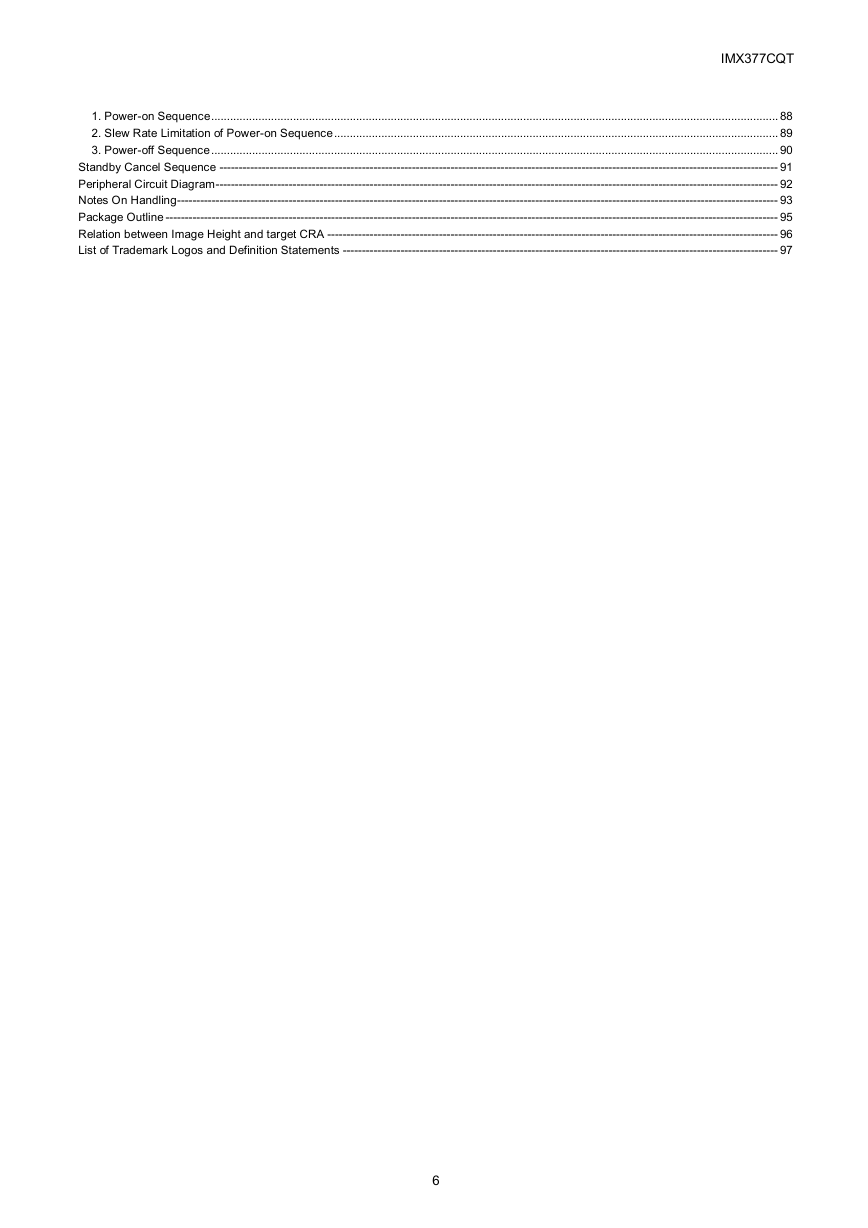
IMX377CQT 1. Power-on Sequence .................................................................................................................................................................................... 88 2. Slew Rate Limitation of Power-on Sequence ............................................................................................................................................. 89 3. Power-off Sequence .................................................................................................................................................................................... 90 Standby Cancel Sequence ------------------------------------------------------------------------------------------------------------------------------------------------- 91 Peripheral Circuit Diagram -------------------------------------------------------------------------------------------------------------------------------------------------- 92 Notes On Handling------------------------------------------------------------------------------------------------------------------------------------------------------------ 93 Package Outline --------------------------------------------------------------------------------------------------------------------------------------------------------------- 95 Relation between Image Height and target CRA --------------------------------------------------------------------------------------------------------------------- 96 List of Trademark Logos and Definition Statements ----------------------------------------------------------------------------------------------------------------- 97 6
Pin Configuration (Bottom View) 1pin index IMX377CQT 1 2 3 4 5 6 7 8 9 10 NC NC NC NC NC NC NC NC VDDHCM VRLS VDDHPX VRLT VLOADLM VSSHPX VDDHCP VSSHCP VDDHDA VSSHDA BIASRES VBGR TEST1 TEST2 NC NC A NC NC B NC NC NC NC NC NC NC NC NC NC NC NC NC NC NC NC NC NC C NC NC NC NC NC NC NC NC NC NC NC NC VDDSUB NC NC VDDLCN1 VDDLSC1 INCK XCLR VDDLPL1 TEST3 NC NC VSSLCB1 VSSLCN1 VSSLSC1 NC NC VSSLPL2 VSSLPL1 TEST4 TEST5 NC NC NC NC VDDLPL3 VDDLPL2 DCKP DMO3N DMO3P VDDLIF1 DCKN DMO1N DMO1P VDDLIF2 DMO4P DMO2N DMO2P VSSLIF1 DMO4N VSSLIF2 NC NC NC NC NC NC VDDMIO NC NC NC NC VSSLCB2 VSSLCN2 VSSLSC2 SDA XVS XHS NC NC D VDDLCN2 VDDLSC2 SCL TEST7 TEST6 E F G H J Pin Configuration NC NC NC NC NC NC NC NC NC NC K NC NC NC NC NC NC NC NC NC NC L 7
Pin Description IMX377CQT Symbol I/O A/D Pin description State in Standby mode Remarks A A A A A A Analog power supply (2.8 V) Analog power supply (2.8 V) Capacitor connection Analog power supply (2.8 V) Analog power supply (2.8 V) Resistor connection D Test A A A A A A D A D D D D D D D D D D D D D D D D D Capacitor connection Capacitor connection Analog GND (2.8 V) Analog GND (2.8 V) Analog GND (2.8 V) Capacitor connection Test Analog power supply (2.8 V) Digital GND (1.2 V) Digital GND (1.2 V) Digital power supply (1.2 V) Digital GND (1.2 V) Digital GND (1.2 V) Digital power supply (1.2 V) Digital power supply (1.2 V) Digital GND (1.2 V) Digital GND (1.2 V) Digital power supply (1.2 V) Input clock Digital power supply (1.2 V) I2C communication data input I2C communication clock input Reset pulse input Digital GND (1.2 V) Digital power supply (1.2 V) — — — — Leave open. (No connection) Leave open. (No connection) Leave open. (No connection) Pull-down Pull-down — — — — — — — — — — — — — — — — — — — — — Leave open. (No connection) Leave open. (No connection) Pin No. A3 A4 VDDHCM Power VDDHPX Power A5 VLOADLM O A6 A7 VDDHCP Power VDDHDA Power A8 BIASRES A9 TEST1 B3 VRLS B4 VRLT B5 B6 B7 VSSHPX VSSHCP VSSHDA B8 VBGR B9 TEST2 O I O O GND GND GND O I C1 VDDSUB Power D2 VSSLCB1 D9 VSSLCB2 GND GND E1 E2 E9 VDDLCN1 Power VSSLCN1 VSSLCN2 GND GND E10 VDDLCN2 Power F1 F2 F9 VDDLSC1 Power VSSLSC1 VSSLSC2 GND GND F10 VDDLSC2 Power G1 INCK I G3 VDDLPL3 Power G9 SDA G10 SCL H1 XCLR I I I H2 VSSLPL2 GND H3 VDDLPL2 Power 8
分享到:
收藏