Ordering number : CNA1482A
LV8731V
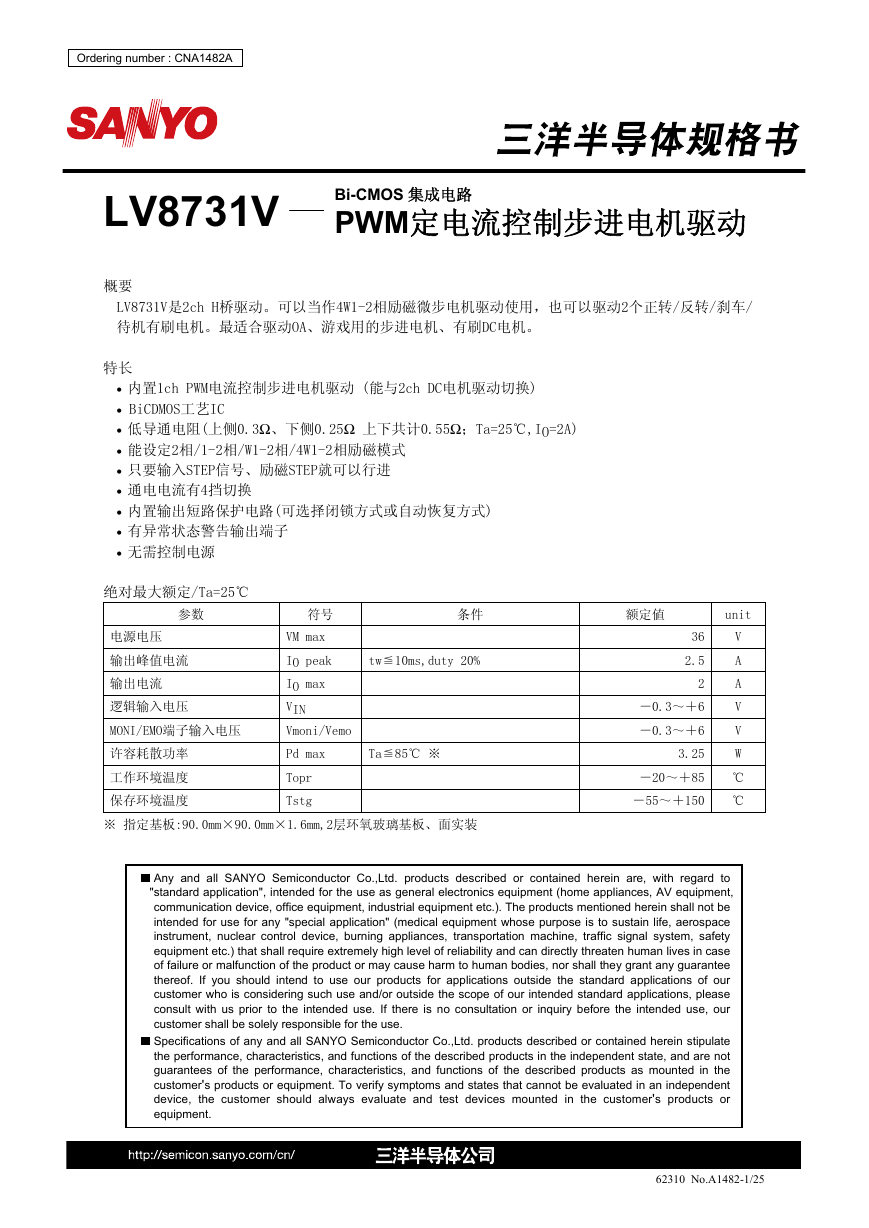
概要
Bi-CMOS 集成电路
PWM定电流控制步进电机驱动
LV8731V是2ch H桥驱动。可以当作4W1-2相励磁微步电机驱动使用,也可以驱动2个正转/反转/刹车/
待机有刷电机。最适合驱动OA、游戏用的步进电机、有刷DC电机。
特长
• 内置1ch PWM电流控制步进电机驱动 (能与2ch DC电机驱动切换)
• BiCDMOS工艺IC
• 低导通电阻(上侧0.3Ω、下侧0.25Ω 上下共计0.55Ω;Ta=25℃,IO=2A)
• 能设定2相/1-2相/W1-2相/4W1-2相励磁模式
• 只要输入STEP信号、励磁STEP就可以行进
• 通电电流有4挡切换
• 内置输出短路保护电路(可选择闭锁方式或自动恢复方式)
• 有异常状态警告输出端子
• 无需控制电源
绝对最大额定/Ta=25℃
参数
符号
条件
额定値
unit
电源电压
输出峰值电流
输出电流
逻辑输入电压
MONI/EMO端子输入电压
许容耗散功率
工作环境温度
保存环境温度
VM max
tw≦10ms,duty 20%
IO peak
IO max
VIN
Vmoni/Vemo
Pd max
Ta≦85℃ ※
Topr
Tstg
36
2.5
2
-0.3~+6
-0.3~+6
3.25
V
A
A
V
V
W
-20~+85 ℃
-55~+150 ℃
※ 指定基板:90.0mm×90.0mm×1.6mm,2层环氧玻璃基板、面实装
Any and all SANYO Semiconductor Co.,Ltd. products described or contained herein are, with regard to
"standard application", intended for the use as general electronics equipment (home appliances, AV equipment,
communication device, office equipment, industrial equipment etc.). The products mentioned herein shall not be
intended for use for any "special application" (medical equipment whose purpose is to sustain life, aerospace
instrument, nuclear control device, burning appliances, transportation machine, traffic signal system, safety
equipment etc.) that shall require extremely high level of reliability and can directly threaten human lives in case
of failure or malfunction of the product or may cause harm to human bodies, nor shall they grant any guarantee
thereof. If you should intend to use our products for applications outside the standard applications of our
customer who is considering such use and/or outside the scope of our intended standard applications, please
consult with us prior to the intended use. If there is no consultation or inquiry before the intended use, our
customer shall be solely responsible for the use.
Specifications of any and all SANYO Semiconductor Co.,Ltd. products described or contained herein stipulate
the performance, characteristics, and functions of the described products in the independent state, and are not
guarantees of the performance, characteristics, and functions of the described products as mounted in the
customer's products or equipment. To verify symptoms and states that cannot be evaluated in an independent
the customer should always evaluate and test devices mounted in the customer's products or
device,
equipment.
62310 No.A1482-1/25
�
LV8731V
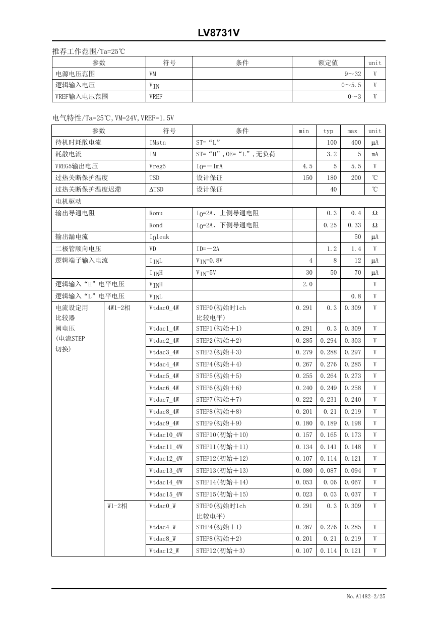
推荐工作范围/Ta=25℃
参数
符号
条件
额定値
unit
电源电压范围
逻辑输入电压
VREF输入电压范围
VM
VIN
VREF
电气特性/Ta=25℃,VM=24V,VREF=1.5V
参数
符号
条件
min
typ
ST=“L”
ST=“H”,OE=“L”,无负荷
100
3.2
9~32
0~5.5
0~3
V
V
V
unit
max
400 μA
5
mA
IMstn
IM
Vreg5
TSD
ΔTSD
Ronu
Rond
IOleak
VD
IINL
IINH
VINH
VINL
Vtdac0_4W
待机时耗散电流
耗散电流
VREG5输出电压
过热关断保护温度
过热关断保护温度迟滞
电机驱动
输出导通电阻
输出漏电流
二极管顺向电压
逻辑端子输入电流
逻辑输入“H”电平电压
逻辑输入“L”电平电压
电流设定用
4W1-2相
比较器
阈电压
(电流STEP
切换)
IO=-1mA
设计保证
设计保证
IO=2A、上侧导通电阻
IO=2A、下侧导通电阻
ID=-2A
VIN=0.8V
VIN=5V
4.5
150
4
30
2.0
5
5.5
V
180
200 ℃
40
℃
0.3
0.25
1.2
8
50
0.4 Ω
0.33 Ω
50 μA
1.4
V
12 μA
70 μA
0.8
STEP0(初始时1ch
0.291
0.3 0.309
比较电平)
Vtdac1_4W
STEP1(初始+1)
0.291
0.3 0.309
Vtdac2_4W
STEP2(初始+2)
0.285 0.294 0.303
Vtdac3_4W
STEP3(初始+3)
0.279 0.288 0.297
Vtdac4_4W
STEP4(初始+4)
0.267 0.276 0.285
Vtdac5_4W
STEP5(初始+5)
0.255 0.264 0.273
Vtdac6_4W
STEP6(初始+6)
0.240 0.249 0.258
Vtdac7_4W
STEP7(初始+7)
0.222 0.231 0.240
Vtdac8_4W
STEP8(初始+8)
0.201
0.21 0.219
Vtdac9_4W
STEP9(初始+9)
0.180 0.189 0.198
Vtdac10_4W
STEP10(初始+10)
0.157 0.165 0.173
Vtdac11_4W
STEP11(初始+11)
0.134 0.141 0.148
Vtdac12_4W
STEP12(初始+12)
0.107 0.114 0.121
Vtdac13_4W
STEP13(初始+13)
0.080 0.087 0.094
Vtdac14_4W
STEP14(初始+14)
0.053
0.06 0.067
Vtdac15_4W
STEP15(初始+15)
0.023
0.03 0.037
W1-2相
Vtdac0_W
STEP0(初始时1ch
0.291
0.3 0.309
比较电平)
Vtdac4_W
STEP4(初始+1)
0.267 0.276 0.285
Vtdac8_W
STEP8(初始+2)
0.201
0.21 0.219
Vtdac12_W
STEP12(初始+3)
0.107 0.114 0.121
V
V
V
V
V
V
V
V
V
V
V
V
V
V
V
V
V
V
V
V
V
V
No.A1482-2/25
�
LV8731V
参数
符号
条件
min
typ
max
unit
电流设定用
1-2相
Vtdac0_H
STEP0(初始时1ch
0.291
0.3 0.309
V
比较器
阈电压
(电流STEP
切换)
比较电平)
Vtdac8_H
STEP8(初始+1)
0.201
0.21 0.219
2相
Vtdac8_F
STEP8'(初始时1ch比较电平)
0.291
0.3 0.309
电流设定用比较器
Vtatt00
ATT1=L,ATT2=L
0.291
0.3 0.309
阈电压
(电流衰减率切换)
间歇频率
CHOP端子充放电电流
间歇振荡电路
阈电压
Vtatt01
ATT1=H,ATT2=L
0.232
0.24 0.248
Vtatt10
ATT1=L,ATT2=H
0.143
0.15 0.157
Vtatt11
ATT1=H,ATT2=H
0.053
0.06 0.067
Fchop
Ichop
Vtup
Cchop=200pF
V
V
V
V
V
V
40
7
50
10
60 kHz
13 μA
0.8
1
1.2
V
-0.5
μA
400
mV
28
28.7
90
200
125
29.8
V
μS
150 kHz
7
10
400
mV
13 μA
0.8
1
1.2
V
VREF端子输入电流
Iref
VREF=1.5V
MONI端子饱和电压
Vsatmon
Imoni=1mA
电荷泵
VG输出电压
上升沿时间
振荡频率
输出短路保护
VG
tONG
Fosc
VG=0.1μF
EMO端子饱和电压
Vsatemo
Iemo=1mA
CEM端子充电电流
CEM端子阈电压
Icem
Vtcem
Vcem=0V
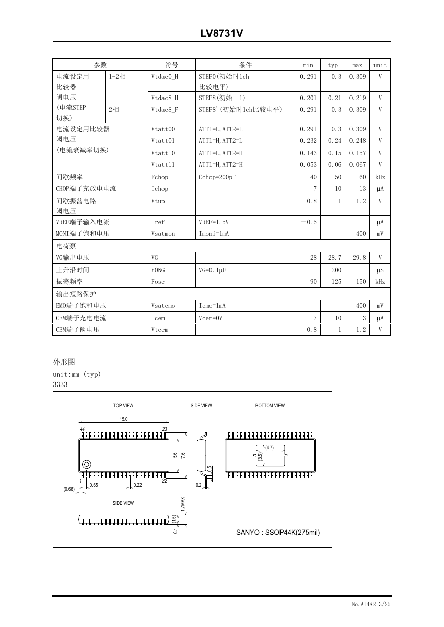
外形图
44
unit:mm (typ)
3333
(0.68)
1
0.65
TOP VIEW
15.0
0.22
SIDE VIEW
SIDE VIEW
BOTTOM VIEW
23
22
.
6
5
.
6
7
X
A
M
7
1
.
.
)
5
1
(
1
.
0
.
5
0
0.2
(4.7)
.
)
5
3
(
SANYO : SSOP44K(275mil)
No.A1482-3/25
�
LV8731V
①:有Exposed Die-Pad 基板实装
②:无 Exposed Die-Pad 基板实装
1.69
1.14
2层基板①
2 层基板②
)
W
(
x
a
m
d
P
率
功
散
耗
容
许
4.0
3.25
3.0
2.20
2.0
1.0
0.0
-20
0
20
40
60
80
100
环境温度 Ta(℃)
基板规格(LV8731V推荐基板)
:90mm×90mm×1.6mm(2层基板[2S0P])
:环氧玻璃
尺寸
材质
铜配线密度 :L1=85%/L2=90%
注意事项
L1:铜配线图案
L2:铜配线图案
1)有Exposed Die-Pad基板实装的数据是Exposed Die-Pad面90%以上湿润状态下的値。
2)请降额设计。
需要降额应力的是电压、电流、接合部温度、功率损失、还有振动、冲击和牵引等机械性应力。
设计时尽量降低这些应力。
一般降额标准。
(1)电压额定、最大値80%以下
(2)电流额定、最大値80%以下
(3)温度额定、最大値80%以下
3)设计后必须检测产品。
确认Exposed Die-Pad等焊点状态,检测焊点的品质。这些部分的焊点如果有破洞和劣化、向基板
的热传导变差、IC可能会有热破坏。
No.A1482-4/25
�
LV8731V
LV8731V
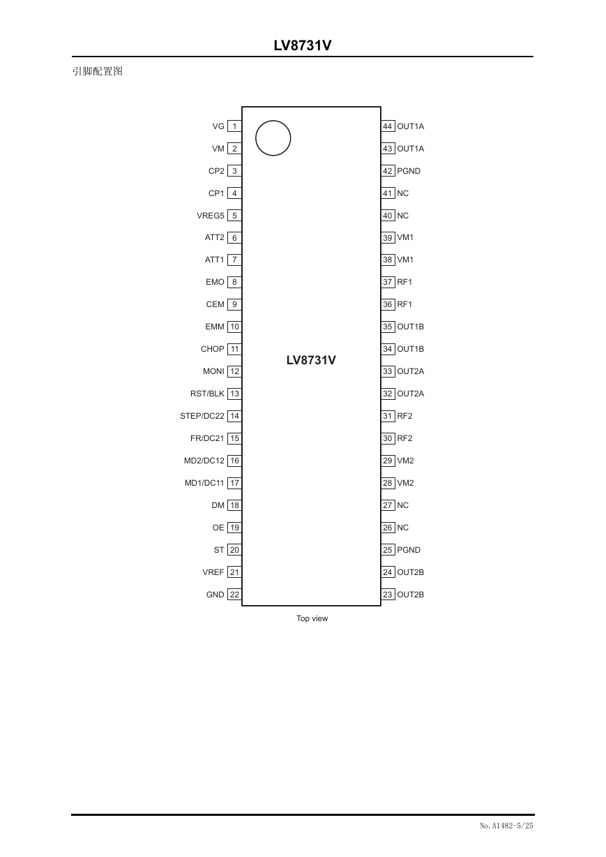
Top view
VG
VM
CP2
CP1
VREG5
ATT2
ATT1
EMO
CEM
1
2
3
4
5
6
7
8
9
EMM
10
CHOP
11
MONI
12
RST/BLK
13
STEP/DC22
14
FR/DC21
15
MD2/DC12
16
MD1/DC11
17
DM
18
OE
19
ST
20
VREF
21
GND
22
44
OUT1A
43
OUT1A
42
PGND
41
NC
40
NC
39
VM1
38
VM1
37
RF1
36
RF1
35
OUT1B
34
OUT1B
33
OUT2A
32
OUT2A
31
RF2
30
RF2
29
VM2
28
VM2
27
NC
26
NC
25
PGND
24
OUT2B
23
OUT2B
引脚配置图
No.A1482-5/25
�
LV8731V
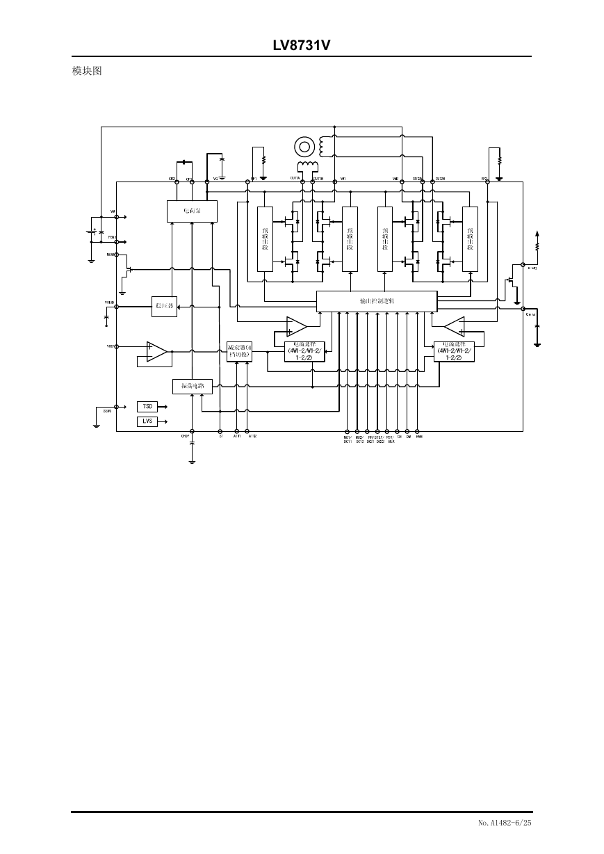
模块图
No.A1482-6/25
�
LV8731V
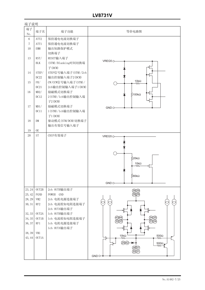
端子说明
端子
No.
端子名
端子功能
等价电路图
6
7
ATT2
ATT1
保持通电电流切换端子
保持通电电流切换端子
10
EMM
输出短路保护模式
切换端子
13
RST/
RESET输入端子
BLK
(STM)/Blanking时间切换端
子(DCM)
14
STEP/
STEP信号输入端子(STM)/2ch
DC22
输出控制输入端子2(DCM)
15
FR/
CW/CCW信号输入端子(STM)/
DC21
2ch输出控制输入端子1(DCM)
16
MD2/
励磁模式切换端子
DC12
2(STM)/1ch输出控制输入端
子2(DCM)
17
MD1/
励磁模式切换端子
DC11
1(STM)/1ch输出控制输入端
子1(DCM)
18
DM
驱动模式(STM/DCM)切换端子
输出有效信号输入端子
VREG5
GND
19
20
OE
ST
CHIP有效端子
VREG5
23,24
OUT2B
2ch OUTB输出端子
25,42
PGND
POWER GND
28,29
VM2
2ch 电机电源连接端子
30,31
RF2
2ch 电流检知电阻连接端子
2ch OUTA输出端子
32,33
OUT2A
1ch OUTB输出端子
34,35
OUT1B
1ch 电流检知电阻连接端子
36,37
RF1
1ch 电机电源连接端子
1ch OUTA输出端子
38,39
VM1
43,44
OUT1A
GND
GND
10kΩ
100kΩ
20kΩ
10kΩ
80kΩ
38 39
28 29
43
32
44
33
34
23
35
24
10kΩ
25
42
36 37
30 31
500Ω
500Ω
No.A1482-7/25
�
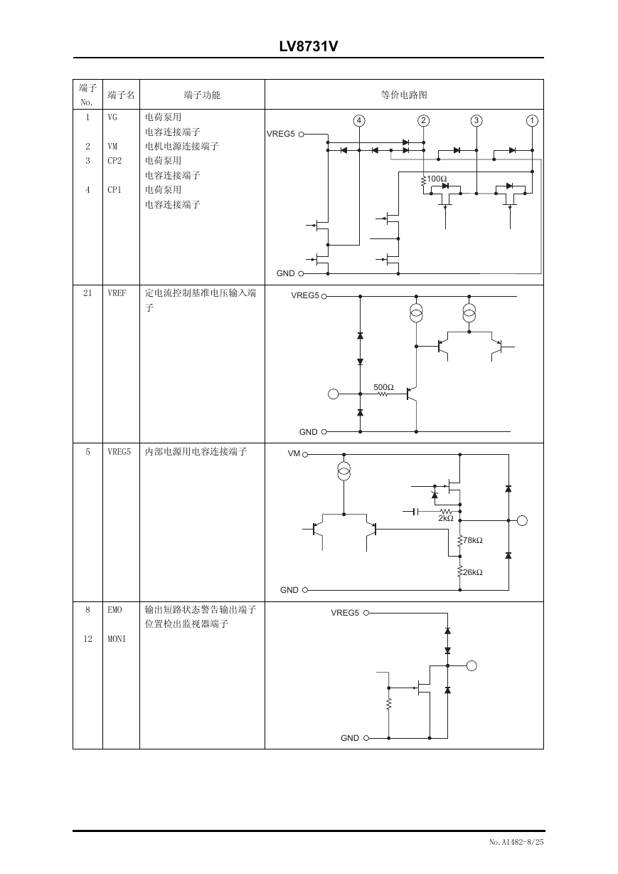
LV8731V
端子
No.
端子名
端子功能
等价电路图
4
2
3
1
100Ω
1
2
3
4
VG
VM
CP2
电荷泵用
电容连接端子
电机电源连接端子
电荷泵用
电容连接端子
CP1
电荷泵用
电容连接端子
VREG5
GND
21
VREF 定电流控制基准电压输入端
VREG5
子
500Ω
5
VREG5 内部电源用电容连接端子
GND
VM
8
EMO
输出短路状态警告输出端子
位置检出监视器端子
12
MONI
GND
VREG5
2kΩ
78kΩ
26kΩ
GND
No.A1482-8/25
�



 2023年江西萍乡中考道德与法治真题及答案.doc
 2012年重庆南川中考生物真题及答案.doc
 2013年江西师范大学地理学综合及文艺理论基础考研真题.doc
 2020年四川甘孜小升初语文真题及答案I卷.doc
 2020年注册岩土工程师专业基础考试真题及答案.doc
 2023-2024学年福建省厦门市九年级上学期数学月考试题及答案.doc
 2021-2022学年辽宁省沈阳市大东区九年级上学期语文期末试题及答案.doc
 2022-2023学年北京东城区初三第一学期物理期末试卷及答案.doc
 2018上半年江西教师资格初中地理学科知识与教学能力真题及答案.doc
 2012年河北国家公务员申论考试真题及答案-省级.doc
 2020-2021学年江苏省扬州市江都区邵樊片九年级上学期数学第一次质量检测试题及答案.doc
 2022下半年黑龙江教师资格证中学综合素质真题及答案.doc