CANoe as a diagnostic tool
Version 1.2
2006/06/06
Application Note AN-IND-1-001
Asa Forsberg, Thomas R. Schmidt
Public Document
This application gives a general introduction into working with diagnostics in CANoe. It
presents the basic technical aspects and possibilities with the Diagnostic Feature
Set.This document complements the help file of CANoe and may be used as a tutorial
Author(s)
Restrictions
Abstract
Table of Contents
1.0
1.1
1.2
1.3
1.4
2.0
2.1
2.2
2.2.1
2.2.2
2.2.3
2.2.4
2.2.5
2.2.6
2.2.7
2.3
3.0
3.1
3.1.1
3.1.2
3.2
3.2.1
3.2.2
3.2.3
3.3
3.3.1
3.3.2
3.3.3
3.3.4
3.3.5
3.3.6
3.3.7
3.3.8
3.3.9
3.3.10
3.3.11
Overview ..........................................................................................................................................................3
Introduction....................................................................................................................................................3
Diagnostic components.................................................................................................................................4
Major changes between CANoe 5.0 and CANoe 5.1....................................................................................4
Major changes between CANoe 5.1 and CANoe 5.2....................................................................................4
Diagnostics in CANoe......................................................................................................................................6
OSEK TP support..........................................................................................................................................6
Diagnostic descriptions .................................................................................................................................6
Trace window..............................................................................................................................................6
Diagnostic Feature Set ...............................................................................................................................6
CAPL ECU simulations...............................................................................................................................7
CAPL tester simulations or test modules....................................................................................................7
Physical Network Request and Network CDD............................................................................................8
Access to diagnostics features via COM ....................................................................................................8
Symbolic selection dialog for diagnostics objects and parameters ............................................................8
KWP2000 and UDS.......................................................................................................................................9
First steps.......................................................................................................................................................10
Usage of diagnostic database files .............................................................................................................10
Add a CDD file ..........................................................................................................................................10
Configure the CDD file..............................................................................................................................10
Usage of Diagnostic Console and Fault Memory Window..........................................................................11
Send a diagnostic request and receive a response..................................................................................11
Read fault memory....................................................................................................................................11
Physical network requests ........................................................................................................................11
Usage of CAPL and CDDs to simulate diagnostics ....................................................................................11
CAPL Browser ..........................................................................................................................................11
Mandatory CAPL functions in ECU simulations and non-standard testers ..............................................11
Mandatory variable ...................................................................................................................................12
Debug level ...............................................................................................................................................12
Create a simulated node with TP functionality .........................................................................................12
Set the diagnostic target ...........................................................................................................................12
Qualifier for Diagnostics request...............................................................................................................13
Qualifier for Diagnostics response............................................................................................................13
Create a diagnostic request......................................................................................................................13
Create a diagnostic response...................................................................................................................14
Work with parameters...............................................................................................................................14
Copyright © 2006 - VecScan AB, Vector Informatik GmbH
Contact Information: www.vector-informatik.com or ++49-711-80 670-0
1
�
3.3.12
3.3.13
3.4
3.4.1
3.4.2
3.4.3
4.0
4.1
4.2
4.3
4.4
4.4.1
4.4.2
4.5
5.0
6.0
7.0
8.0
9.0
CANoe as a diagnostic tool
Timeout handling ......................................................................................................................................16
Negative Response handling....................................................................................................................16
Combine Test Feature Set and Diagnostic Feature Set .............................................................................16
Difference between a Prog Node (ECU) and Test Module ......................................................................17
A simple Diagnostic Tester .......................................................................................................................17
Diagnostics tests with XML patterns.........................................................................................................18
Advanced examples.......................................................................................................................................20
ECU simulation of “Response Pending”......................................................................................................20
Modifying the length of a diagnostic object .................................................................................................21
Fill diagnostic content..................................................................................................................................21
Fault injection ..............................................................................................................................................22
Make request length illegal .......................................................................................................................22
Introduce errors on transport protocol level..............................................................................................22
Access LIN node via a CAN-LIN gateway simulation .................................................................................23
Common mistakes .........................................................................................................................................24
Abbreviations .................................................................................................................................................27
References.....................................................................................................................................................27
Additional Resources .....................................................................................................................................27
Contacts.........................................................................................................................................................27
Application Note AN-IND-1-001
2
�
1.0 Overview
CANoe as a diagnostic tool
Introduction
1.1
Diagnostics is used to configure, maintain, support, control and extend an ECU before or after it is installed in a
system, e.g. a vehicle. Diagnostics is usually performed in a request – response scheme: a tester (client) sends a
request to an ECU (or even more than one ECU) and the ECU(s) (server) respond(s) by sending a “positive
response message” containing the requested information, or a “negative response” indicating the reason for the
negative response.
The purpose of this application note is to give a general introduction into working with diagnostics in the Vector tool
CANoe. The basic technical aspects and possibilities (“first steps”) with the Diagnostic Feature Set will be
presented. Examples are used to get the test engineer started with testing diagnostics in CANoe.
This document is a complement to the help file of CANoe and should be used as a tutorial to learn the “first steps”
of the Diagnostic Feature Set. For more detailed information about the Diagnostic Feature Set, please refer to the
CANoe help file and to CANoe demo applications, both of which come with a standard CANoe installation.
Note:
The functionality described here refers to CANoe (and CANalyzer) version 5.2. For older program
versions application notes can be requested from the Vector support (cf. 9.0).
Application Note AN-IND-1-001
3
�
CANoe as a diagnostic tool
1.2 Diagnostic components
The following table lists the names of the components relevant for diagnostics in CANoe, how to activate them and
where to find more information.
Description
Component
Implementation of the ISO TP
OSEK TP DLL
for CANoe simulation nodes
More information
Doc/osek_tp_e.pdf
ISO TP
Observer
KWP 2000
interpreter
Diagnostics
interpreter
Diagnostics
console
Displays TP information for
the CAN messages used by
the ISO TP
Extension of the ISO TP
Observer that interprets the
transported data according to
KWP 2000
Extension of the ISO TP
Observer, interpret the
transported data according to
the specifications in a CDD
Direct sending of requests
defined in a CDD, display of
responses
Fault memory
window
Direct access to an ECU’s
fault memory
CAPL
extensions for
diagnostics
K-Line DLL
Specialized CAPL functions to
access diagnostics objects
specified via CDDs
CAPL DLL to access an ECU
via K-Line (Ser2K)
Activation
Database:
“NodeLayerModules”,
simulation setup: node
configuration/“Modules”
Menu Configure,
Diagnostics/ISO TP
configuration, Standard
Like ISO TP Observer, check
box “Interpretation according
to KWP2000”
Menu Configure,
Diagnostics/ISO TP
configuration, diagnostics
description (load a CDD)
Menu Configure,
Diagnostics/ISO TP
configuration, diagnostics
description (assign CDD to a
bus or node!)
Menu Configure,
Diagnostics/ISO TP
configuration, diagnostics
description (assign CDD to a
bus or node!)
Load CDDs, usable from
CAPL programs
“Diagnostics/ISO TP
Configuration: Standard”
“Diagnostics/ISO TP
Configuration: Standard”
“Diagnostics/ISO TP
Configuration: Diagnostics
Descriptions”
“Diagnostics Console:
Overview”
“Fault Memory Window:
Overview”
“Expanded Diagnostics
Functions in CAPL”
Activate as CAPL DLL
“Doc/KLineCAPL_Manual.pdf”
1.3 Major changes between CANoe 5.0 and CANoe 5.1
• The usage of the KWP2000.DLL is discouraged. It is more comfortable and flexible to use a “Generic
CDD” and the CDD mechanisms (2.3).
It is possible to configure VW TP 2.0 for communicating with an ECU. Please refer to the document
“DiagnosticsInCANoe.pdf” provided with the VAG Addon packet.
•
• For CAPL tester implementations that do not need to influence the TP level behavior, it is no longer
necessary to implement a CAPL callback interface. Instead the communication mechanism for the
diagnostics console and the fault memory window is used (3.3.2).
In the CAPL browser a dialog for the symbolic selection of diagnostics object and parameter qualifiers can
be opened from the context menu (2.2.7).
•
1.4 Major changes between CANoe 5.1 and CANoe 5.2
• The CAPL callback interface has been rewritten and needs only three functions to handle all protocol
settings implemented. Confer the sample code for details (3.3.2).
functionality can be accessed via
the automation (COM)
interface (cf. help
4
• The diagnostics
documentation).
Application Note AN-IND-1-001
�
CANoe as a diagnostic tool
• Simple diagnostics tests can be implemented using XML patterns (3.4.3).
• Physical network requests can now be sent from the diagnostics console and the fault memory window
(2.2.5).
• There is a global options dialog for diagnostics (cf. help documentation).
• Diagnostics parameters can be displayed in data and graphics windows (cf. help documentation, topic
“Diagnostics Parameters“).
It is possible to access LIN nodes (cf. help documentation, 4.5).
•
• TP level events (including diagnostics events) can be processed and filtered in the measurement setup (cf.
help documentation, topic “CallbackTPDataIndication”).
Application Note AN-IND-1-001
5
�
CANoe as a diagnostic tool
2.0 Diagnostics in CANoe
CANoe can be used in all steps of developing ECUs and performing diagnostics on them:
• Design of the diagnostic functionality (system simulation)
•
Implementation of diagnostic functionality in an ECU (remaining bus simulation)
OSEK TP DLL and CAPL extensions, using a (generic) CDD
• Specification-/Integration-/Regression tests
CAPL extensions using a (generic) CDD AND CANoe test support. OSEK TP DLL only necessary if TP
fault injection requested.
• Analysis of real ECU communication
ISO TP Observer OR KWP2000 Interpreter OR Diagnostics Interpreter
• Perform diagnostics of ECUs with integrated tester functionality
diagnostics console
• Error search
fault memory console
2.1 OSEK TP support
CANoe includes the OSEK TP Observer, which interprets messages sent over the CAN bus according to the
OSEK Transport Protocol ISO/TF2 and displays the results in the Trace Window in clear text. It also includes an
implementation of the transport protocol that enables easy sending and receiving of diagnostic objects. This
implementation is realized by a node layer DLL that comes with every CANoe standard installation and takes care
of transport protocol specific functions such as segmentation, flow control etc.
To enable transport layer interpretation it is needed to activate the ISO TP Observer. Please refer to the help file of
CANoe on how to activate the observer.
To enable the TP functionality for a simulated node, please refer to paragraph 3.3.5.
2.2 Diagnostic descriptions
CANdela Diagnostic Descriptions (CDD) files are databases for diagnostic data, comparable to the DBC file used
for CAN messages and signals. The CDD files are created in the Vector tool CANdelaStudio and can be used in
CANoe and CANalyzer for symbolic access and interpretation of diagnostic services and parameters.
Note 1:
Note 2:
CANalyzer only has interpretation capabilities.
The below mentioned features can only be used after including a CDD file into the CANoe
configuration.
2.2.1 Trace window
A CDD file allows tracing diagnostic services (requests/responses) and their parameters in a symbolic fashion. You
can expand the requests/responses in the same way as with ordinary bus messages.
2.2.2 Diagnostic Feature Set
The Vector Diagnostic Feature Set includes several functions that are necessary for development, test and
application of ECUs with/via diagnostics.
Based on the diagnostic description files (*.CDD) of CANdela Studio the Diagnostics Console — part of the
Diagnostic Feature Set — provides interactive access to all diagnostic services. Diagnostic requests can be
selected, parameterised and displayed with their according response.
The Fault Memory Console provides quick and easy access to the fault memory of an ECU.
Application Note AN-IND-1-001
6
�
Apart from CANoe the Diagnostic Features Set is also included in the Vector products CANape MC+D and
CANdito. Thereby the complete development process is supported identically.
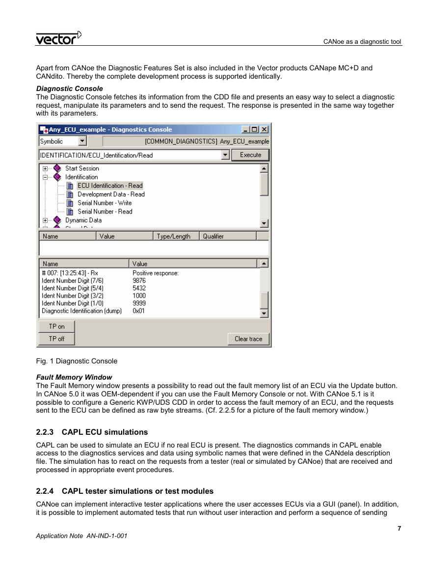
Diagnostic Console
The Diagnostic Console fetches its information from the CDD file and presents an easy way to select a diagnostic
request, manipulate its parameters and to send the request. The response is presented in the same way together
with its parameters.
CANoe as a diagnostic tool
Fig. 1 Diagnostic Console
Fault Memory Window
The Fault Memory window presents a possibility to read out the fault memory list of an ECU via the Update button.
In CANoe 5.0 it was OEM-dependent if you can use the Fault Memory Console or not. With CANoe 5.1 is it
possible to configure a Generic KWP/UDS CDD in order to access the fault memory of an ECU, and the requests
sent to the ECU can be defined as raw byte streams. (Cf. 2.2.5 for a picture of the fault memory window.)
2.2.3 CAPL ECU simulations
CAPL can be used to simulate an ECU if no real ECU is present. The diagnostics commands in CAPL enable
access to the diagnostics services and data using symbolic names that were defined in the CANdela description
file. The simulation has to react on the requests from a tester (real or simulated by CANoe) that are received and
processed in appropriate event procedures.
2.2.4 CAPL tester simulations or test modules
CANoe can implement interactive tester applications where the user accesses ECUs via a GUI (panel). In addition,
it is possible to implement automated tests that run without user interaction and perform a sequence of sending
Application Note AN-IND-1-001
7
�
requests and processing of responses. The result of such a test can be written to a report file (in XML/HTML
format).
Common tests can even be implemented without a CAPL program in a XML test specification.
CANoe as a diagnostic tool
2.2.5 Physical Network Request and Network CDD
With CANoe 5.1 it is possible to specify one CDD per CAN bus as “network CDD”, indicating that all ECUs on the
bus implement the CDD’s content as common subset. The network CDD can then be selected as target in CAPL
programs, and when a request is sent, it will be sent physically to every ECU. The responses received from the
ECUs will be processed individually in the tester.
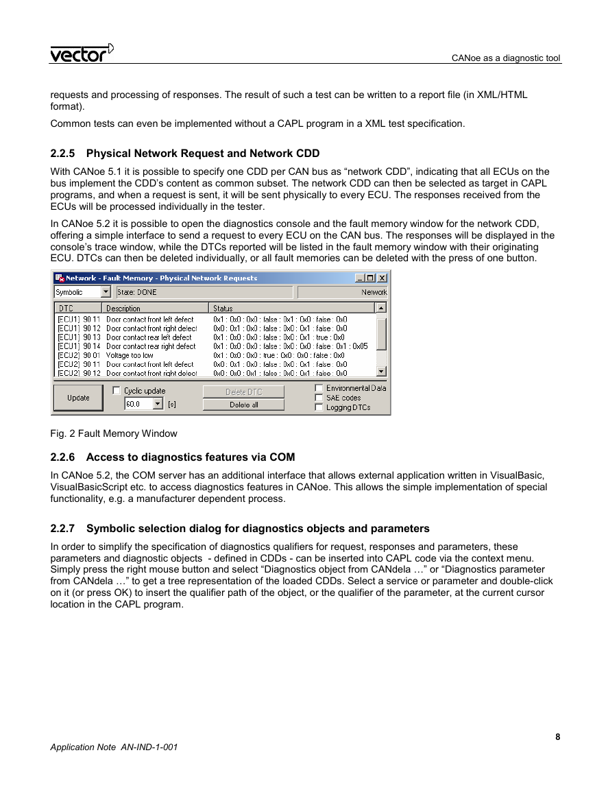
In CANoe 5.2 it is possible to open the diagnostics console and the fault memory window for the network CDD,
offering a simple interface to send a request to every ECU on the CAN bus. The responses will be displayed in the
console’s trace window, while the DTCs reported will be listed in the fault memory window with their originating
ECU. DTCs can then be deleted individually, or all fault memories can be deleted with the press of one button.
Fig. 2 Fault Memory Window
2.2.6 Access to diagnostics features via COM
In CANoe 5.2, the COM server has an additional interface that allows external application written in VisualBasic,
VisualBasicScript etc. to access diagnostics features in CANoe. This allows the simple implementation of special
functionality, e.g. a manufacturer dependent process.
2.2.7 Symbolic selection dialog for diagnostics objects and parameters
In order to simplify the specification of diagnostics qualifiers for request, responses and parameters, these
parameters and diagnostic objects - defined in CDDs - can be inserted into CAPL code via the context menu.
Simply press the right mouse button and select “Diagnostics object from CANdela …” or “Diagnostics parameter
from CANdela …” to get a tree representation of the loaded CDDs. Select a service or parameter and double-click
on it (or press OK) to insert the qualifier path of the object, or the qualifier of the parameter, at the current cursor
location in the CAPL program.
Application Note AN-IND-1-001
8
�


 2023年江西萍乡中考道德与法治真题及答案.doc
 2012年重庆南川中考生物真题及答案.doc
 2013年江西师范大学地理学综合及文艺理论基础考研真题.doc
 2020年四川甘孜小升初语文真题及答案I卷.doc
 2020年注册岩土工程师专业基础考试真题及答案.doc
 2023-2024学年福建省厦门市九年级上学期数学月考试题及答案.doc
 2021-2022学年辽宁省沈阳市大东区九年级上学期语文期末试题及答案.doc
 2022-2023学年北京东城区初三第一学期物理期末试卷及答案.doc
 2018上半年江西教师资格初中地理学科知识与教学能力真题及答案.doc
 2012年河北国家公务员申论考试真题及答案-省级.doc
 2020-2021学年江苏省扬州市江都区邵樊片九年级上学期数学第一次质量检测试题及答案.doc
 2022下半年黑龙江教师资格证中学综合素质真题及答案.doc