IEEE TRANSACTIONS ON POWER ELECTRONICS, VOL. 23, NO. 3, MAY 2008
1191
Modeling and Control of Brushless Doubly-Fed
Induction Generators in Wind Energy Applications
Kostyantyn Protsenko and Dewei Xu, Member, IEEE
Abstract—The development of the brushless doubly-fed induc-
tion generator (BDFIG) system and flexible power flow controller
for the wind energy conversion is proposed in this paper. The
system employs two cascaded induction machines to eliminate the
brushes and copper rings in the traditional DFIG. The dynamic
model of BDFIG with two machines’ rotor electromechanically
interconnected is presented and the control strategy for flexible
power flow control
is developed. The independent control of
the active and reactive power flows is achieved by means of a
four quadrant power converter under the closed-loop stator flux
oriented control scheme. The experimental results obtained verify
the proposed controller scheme, which allows wide operational
range and reactive power control.
Index Terms—Brushless doubly-fed induction generator
(BDFIG), maximum power point tracking (MPPT), power flow,
wind energy conversion.
I. INTRODUCTION
OVER the last twenty years, the wind energy generation
industry has been growing rapidly (at 40% per year),
moving fast to sustain more than 20% of the electricity in some
countries [1]. Recently the doubly fed induction generators
(DFIG) became the popular configuration in variable speed
wind energy applications [2]. The development and use of the
DFIG machines was dictated by the need for wide operational
range as well as the necessity to allow flexible power flow con-
trol, grid integration as well as economic reasons [3]. The use
of the DFIG machines, however, increased the long term cost
and complexity of the wind energy generation. The problems
are major because of the wound-type rotor, which requires
brushes and copper rings for the power transfer to or from
the rotor windings. These aspects create the need for frequent
inspections and maintenance of the generator due to the brushes
wear and carbon accumulations on the internal components [4].
The cost of maintenance for traditional DFIG based wind
generators increased the pressure to seek other alternative gen-
erator systems. In this paper the brushless doubly fed induction
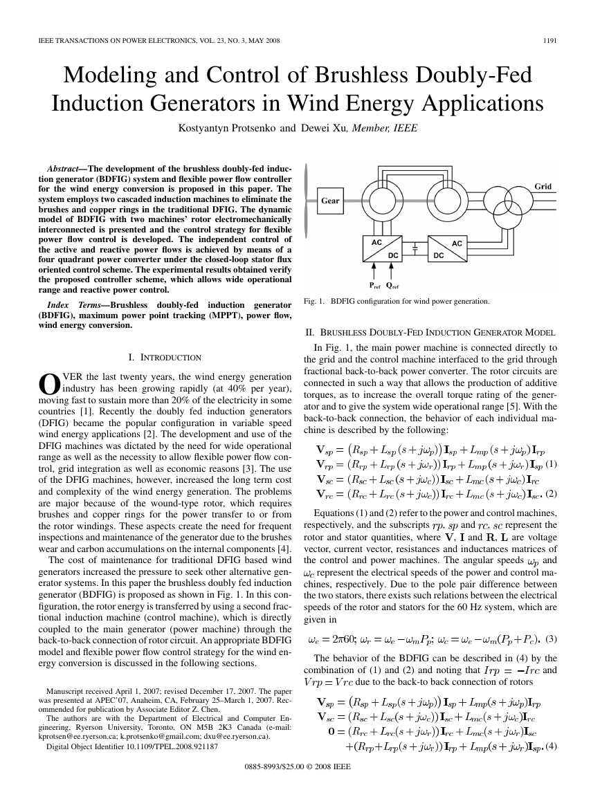
generator (BDFIG) is proposed as shown in Fig. 1. In this con-
figuration, the rotor energy is transferred by using a second frac-
tional induction machine (control machine), which is directly
coupled to the main generator (power machine) through the
back-to-back connection of rotor circuit. An appropriate BDFIG
model and flexible power flow control strategy for the wind en-
ergy conversion is discussed in the following sections.
Manuscript received April 1, 2007; revised December 17, 2007. The paper
was presented at APEC’07, Anaheim, CA, February 25–March 1, 2007. Rec-
ommended for publication by Associate Editor Z. Chen.
The authors are with the Department of Electrical and Computer En-
gineering, Ryerson University, Toronto, ON M5B 2K3 Canada (e-mail:
kprotsen@ee.ryerson.ca; k.protsenko@gmail.com; dxu@ee.ryerson.ca).
Digital Object Identifier 10.1109/TPEL.2008.921187
Fig. 1. BDFIG configuration for wind power generation.
II. BRUSHLESS DOUBLY-FED INDUCTION GENERATOR MODEL
In Fig. 1, the main power machine is connected directly to
the grid and the control machine interfaced to the grid through
fractional back-to-back power converter. The rotor circuits are
connected in such a way that allows the production of additive
torques, as to increase the overall torque rating of the gener-
ator and to give the system wide operational range [5]. With the
back-to-back connection, the behavior of each individual ma-
chine is described by the following:
(1)
(2)
,
and
,
,
and
Equations (1) and (2) refer to the power and control machines,
represent the
respectively, and the subscripts
rotor and stator quantities, where
are voltage
vector, current vector, resistances and inductances matrices of
and
the control and power machines. The angular speeds
represent the electrical speeds of the power and control ma-
chines, respectively. Due to the pole pair difference between
the two stators, there exists such relations between the electrical
speeds of the rotor and stators for the 60 Hz system, which are
given in
,
The behavior of the BDFIG can be described in (4) by the
and
combination of (1) and (2) and noting that
due to the back-to back connection of rotors
(3)
(4)
0885-8993/$25.00 © 2008 IEEE
�
1192
IEEE TRANSACTIONS ON POWER ELECTRONICS, VOL. 23, NO. 3, MAY 2008
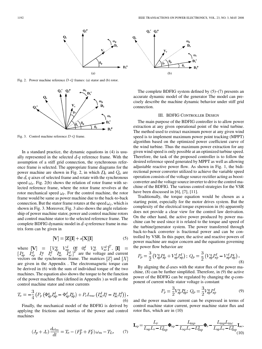
Fig. 2. Power machine reference D-Q frames: (a) stator and (b) rotor.
Fig. 3. Control machine reference D-Q frame.
and
In a standard practice, the dynamic equations in (4) is usu-
ally represented in the selected -
reference frame. With the
assumption of a stiff grid connection, the synchronous refer-
ence frame is selected. The appropriate frame diagrams for the
are
power machine are shown in Fig. 2, in which
aixes of selected frame and rotate with the synchronous
the ,
. Fig. 2(b) shows the relation of rotor frame with se-
speed
lected reference frame, where the rotor frame revolves at the
. For the control machine, the rotor
rotor mechanical speed
frame would be same as power machine due to the back-to-back
, which is
connection. But the stator frame rotates at the speed
shown in Fig. 3. Moreover, Fig. 3 also shows the angle relation-
ship of power machine stator, power and control machine rotors
and control machine stator to the selected reference frame. The
complete BDFIG dynamic model in – reference frame in ma-
trix form can be given in
where
(5)
,
are the voltage and current
vectors on the synchronous frame. The matrices
are given in the Appendix . The electromagnetic torque can
be derived in (6) with the sum of individual torque of the two
machines. The equation also shows the torque to be the function
of the power machine flux (defined in Appendix ) as well as the
control machine stator and rotor currents
and
The complete BDFIG system defined by (5)–(7) presents an
accurate dynamic model of the generator The model can pre-
cisely describe the machine dynamic behavior under stiff grid
connection.
III. BDFIG CONTROLLER DESIGN
The main purpose of the BDFIG controller is to allow power
extraction at any given operational point of the wind turbine.
The method used to extract maximum power at any given wind
speed is to implement maximum power point tracking (MPPT)
algorithm based on the optimized power coefficient curve of
the wind turbine. Thus the maximum power extraction for any
given wind speed is only possible at an optimized turbine speed.
Therefore, the task of the proposed controller is to follow the
desired reference speed generated by MPPT as well as allowing
adjustable reactive power flow. As shown in Fig. 1, the bidi-
rectional power converter utilized to achieve the variable speed
operation consists of the voltage source rectifier acting as boost-
converter and the voltage source inverter to drive the control ma-
chine of the BDFIG. The various control strategies for the VSR
have been discussed in [6], [7], [11].
Traditionally, the torque equation would be chosen as a
starting point, especially for the motor drives system. But the
complexity of the electrical torque expression in (6) apparently
does not provide a clear view for the control law derivation.
On the other hand, the active power produced by power ma-
chine can be used since it is related to the torque and speed of
the turbine/generator system. The power transferred through
back-to-back converter is fractional power and can be con-
trolled by VSR. In this paper, the active and reactive powers of
power machine are major concern and the equations governing
the power flow behavior are
(8)
By aligning the -axes with the stator flux of the power ma-
chine, (8) can be further simplified. Therefore, in (9) the active
power of the BDFIG can be regulated by changing the -com-
ponent of current while stator voltage is constant
(9)
(6)
Finally, the mechanical model of the BDFIG is derived by
applying the frictions and inertias of the power and control
machines
and the power machine current can be expressed in terms of
control machine stator current, power machine stator flux and
rotor flux, which are in (10)
(7)
(10)
�
PROTSENKO AND XU: MODELING AND CONTROL OF BDFIGS
1193
Fig. 4. Linear BDGIF plant model.
Fig. 5. BDFIG controller structure.
Fig. 6. DSP/FPGA controller structure.
The above equation shows that there exists an electrical cou-
pling between the control machine stator through the rotor to the
power machine stator and also shows that the power machine
stator current can be regulated control machine stator current if
�
1194
IEEE TRANSACTIONS ON POWER ELECTRONICS, VOL. 23, NO. 3, MAY 2008
Fig. 7. BDFIG setup.
EXPERIMENTAL BDFIG POWER/CONTROL MACHINE PARAMETERS
TABLE I
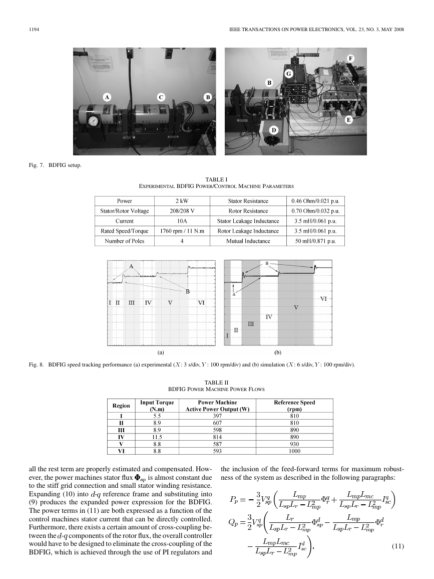
Fig. 8. BDFIG speed tracking performance (a) experimental (X: 3 s/div, Y : 100 rpm/div) and (b) simulation (X: 6 s/div, Y : 100 rpm/div).
TABLE II
BDFIG POWER MACHINE POWER FLOWS
all the rest term are properly estimated and compensated. How-
is almost constant due
ever, the power machines stator flux
to the stiff grid connection and small stator winding resistance.
Expanding (10) into -
reference frame and substituting into
(9) produces the expanded power expression for the BDFIG.
The power terms in (11) are both expressed as a function of the
control machines stator current that can be directly controlled.
Furthermore, there exists a certain amount of cross-coupling be-
tween the - components of the rotor flux, the overall controller
would have to be designed to eliminate the cross-coupling of the
BDFIG, which is achieved through the use of PI regulators and
the inclusion of the feed-forward terms for maximum robust-
ness of the system as described in the following paragraphs:
(11)
�
PROTSENKO AND XU: MODELING AND CONTROL OF BDFIGS
1195
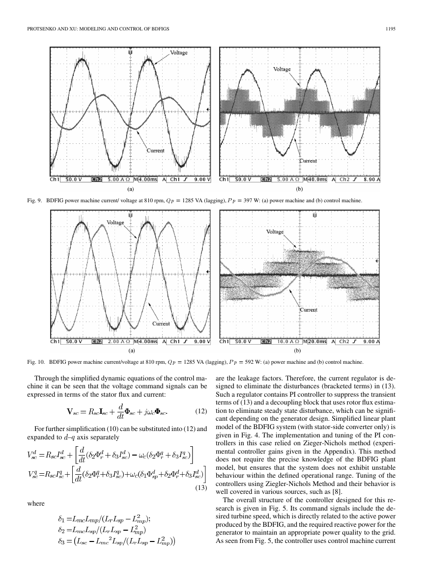
Fig. 9. BDFIG power machine current/ voltage at 810 rpm, Qp = 1285 VA (lagging), P p = 397 W: (a) power machine and (b) control machine.
Fig. 10. BDFIG power machine current/voltage at 810 rpm, Qp = 1285 VA (lagging), P p = 592 W: (a) power machine and (b) control machine.
Through the simplified dynamic equations of the control ma-
chine it can be seen that the voltage command signals can be
expressed in terms of the stator flux and current:
(12)
For further simplification (10) can be substituted into (12) and
expanded to – axis separately
where
(13)
are the leakage factors. Therefore, the current regulator is de-
signed to eliminate the disturbances (bracketed terms) in (13).
Such a regulator contains PI controller to suppress the transient
terms of (13) and a decoupling block that uses rotor flux estima-
tion to eliminate steady state disturbance, which can be signifi-
cant depending on the generator design. Simplified linear plant
model of the BDFIG system (with stator-side converter only) is
given in Fig. 4. The implementation and tuning of the PI con-
trollers in this case relied on Zieger-Nichols method (experi-
mental controller gains given in the Appendix). This method
does not require the precise knowledge of the BDFIG plant
model, but ensures that the system does not exhibit unstable
behaviour within the defined operational range. Tuning of the
controllers using Ziegler-Nichols Method and their behavior is
well covered in various sources, such as [8].
The overall structure of the controller designed for this re-
search is given in Fig. 5. Its command signals include the de-
sired turbine speed, which is directly related to the active power
produced by the BDFIG, and the required reactive power for the
generator to maintain an appropriate power quality to the grid.
As seen from Fig. 5, the controller uses control machine current
�
1196
IEEE TRANSACTIONS ON POWER ELECTRONICS, VOL. 23, NO. 3, MAY 2008
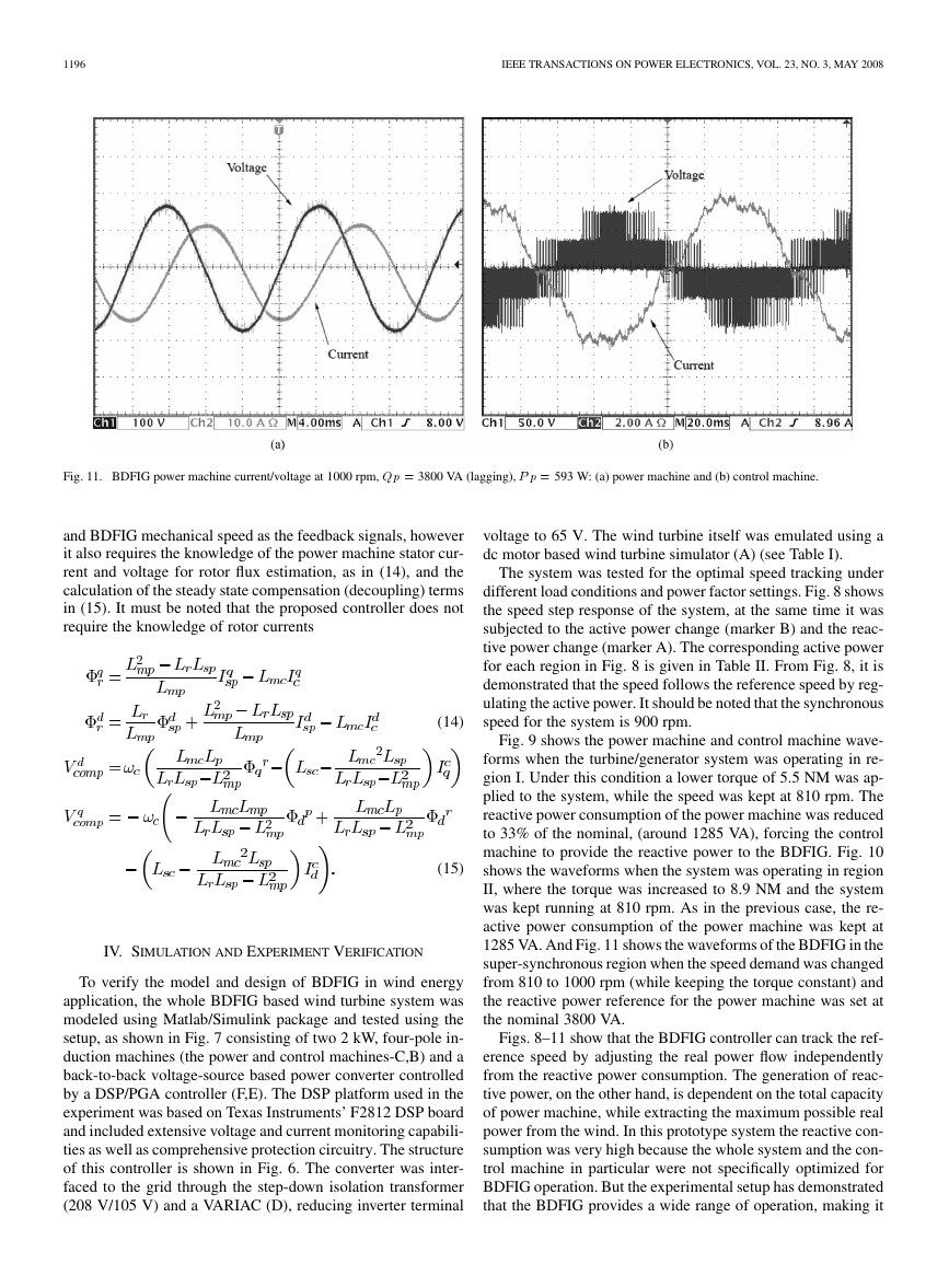
Fig. 11. BDFIG power machine current/voltage at 1000 rpm, Qp = 3800 VA (lagging), P p = 593 W: (a) power machine and (b) control machine.
and BDFIG mechanical speed as the feedback signals, however
it also requires the knowledge of the power machine stator cur-
rent and voltage for rotor flux estimation, as in (14), and the
calculation of the steady state compensation (decoupling) terms
in (15). It must be noted that the proposed controller does not
require the knowledge of rotor currents
(14)
(15)
IV. SIMULATION AND EXPERIMENT VERIFICATION
To verify the model and design of BDFIG in wind energy
application, the whole BDFIG based wind turbine system was
modeled using Matlab/Simulink package and tested using the
setup, as shown in Fig. 7 consisting of two 2 kW, four-pole in-
duction machines (the power and control machines-C,B) and a
back-to-back voltage-source based power converter controlled
by a DSP/PGA controller (F,E). The DSP platform used in the
experiment was based on Texas Instruments’ F2812 DSP board
and included extensive voltage and current monitoring capabili-
ties as well as comprehensive protection circuitry. The structure
of this controller is shown in Fig. 6. The converter was inter-
faced to the grid through the step-down isolation transformer
(208 V/105 V) and a VARIAC (D), reducing inverter terminal
voltage to 65 V. The wind turbine itself was emulated using a
dc motor based wind turbine simulator (A) (see Table I).
The system was tested for the optimal speed tracking under
different load conditions and power factor settings. Fig. 8 shows
the speed step response of the system, at the same time it was
subjected to the active power change (marker B) and the reac-
tive power change (marker A). The corresponding active power
for each region in Fig. 8 is given in Table II. From Fig. 8, it is
demonstrated that the speed follows the reference speed by reg-
ulating the active power. It should be noted that the synchronous
speed for the system is 900 rpm.
Fig. 9 shows the power machine and control machine wave-
forms when the turbine/generator system was operating in re-
gion I. Under this condition a lower torque of 5.5 NM was ap-
plied to the system, while the speed was kept at 810 rpm. The
reactive power consumption of the power machine was reduced
to 33% of the nominal, (around 1285 VA), forcing the control
machine to provide the reactive power to the BDFIG. Fig. 10
shows the waveforms when the system was operating in region
II, where the torque was increased to 8.9 NM and the system
was kept running at 810 rpm. As in the previous case, the re-
active power consumption of the power machine was kept at
1285 VA. And Fig. 11 shows the waveforms of the BDFIG in the
super-synchronous region when the speed demand was changed
from 810 to 1000 rpm (while keeping the torque constant) and
the reactive power reference for the power machine was set at
the nominal 3800 VA.
Figs. 8–11 show that the BDFIG controller can track the ref-
erence speed by adjusting the real power flow independently
from the reactive power consumption. The generation of reac-
tive power, on the other hand, is dependent on the total capacity
of power machine, while extracting the maximum possible real
power from the wind. In this prototype system the reactive con-
sumption was very high because the whole system and the con-
trol machine in particular were not specifically optimized for
BDFIG operation. But the experimental setup has demonstrated
that the BDFIG provides a wide range of operation, making it
�
PROTSENKO AND XU: MODELING AND CONTROL OF BDFIGS
1197
possible to maximize the power extraction with an appropriate
MPPT algorithm.
Some preliminary comparison of the simulation results of
DFIG and BDFIG of identical power ratings also showed that
the latter has the increased benefit of almost uniform efficiency
throughout its operational range. However, further work is re-
quired to produce optimal design of a BDFIG, to reduce its size
and maximize the efficiency [9], [10].
V. CONCLUSION
In this paper, a BDFIG model and controller design for
wind energy applications was proposed. The mathematical
model of the BDFIG was develop and implemented using
Matlab/Simulink. Based on that model, the controller scheme
was designed and tested using the simulation package. Both
the simulation and experimental data obtained verified the
model and the flexible power flow control for the BDFIG. The
observations made during the experiment have confirmed that
the controller allows independent speed and reactive power
regulation. It was verified experimentally that the controller
structure allows both the wide range of the operational wind
speed as well as appropriate reactive power compensation. The
results have also indicated that the design of the generator itself
have the direct impact on the efficiency of the system with re-
gards to the reactive power capability. It has been demonstrated
in this paper that the proposed BDFIG system can be used
for the large off-shore wind energy application with reduced
system maintenance cost.
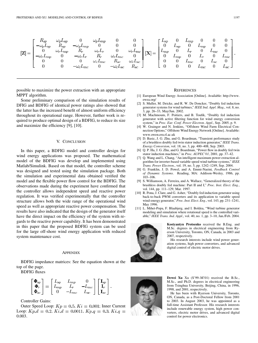
APPENDIX
BDFIG impedance matrices: See the equation shown at the
top of the page.
BDFIG fluxes
Controller Gains:
Outer Speed Loop:
,
Loop:
0.003.
,
,
; Inner Current
,
REFERENCES
[1] European Wind Energy Association [Online]. Available: http://www.
ewea.org/
[2] S. Muller, M. Deicke, and R. W. De Doncker, “Doubly fed induction
generator systems for wind turbines,” IEEE Ind. Appl. Mag., vol. 8, no.
3, pp. 26–33, May/Jun. 2002.
[3] M. Machmoum, F. Poitiers, and B. Toufik, “Doubly fed induction
generator with active filtering function for wind energy conversion
system,” in Proc. Eur. Conf. Power Electron. Appl., Sep. 2005, p. 9.
[4] W. Grainger and N. Jenkins, “Offshore Wind Farm Electrical Con-
nection Options,” Offshore Wind Energy Network [Online]. Available:
www.owen.eru.rl.ac.uk
[5] D. Basic, J. G. Zhu, and G. Boardman, “Transient performance study
of a brushless doubly fed twin stator induction generator,” IEEE Trans.
Energy Conversion, vol. 18, no. 3, pp. 400–408, Sep. 2003.
[6] Q. P. Ha, J. G. Zhu, and G. Boardman, “Power flow in doubly fed twin
stator induction machines,” in Proc. AUPEC’01, 2001, pp. 37–42.
[7] Q. Wang and L. Chang, “An intelligent maximum power extraction al-
gorithm for inverter-based variable speed wind turbine systems,” IEEE
Trans. Power Electron., vol. 19, no. 5, pp. 1242–1249, Sep. 2004.
[8] G. Franklin, J. D. Powel, and A. Emmi-Naeini, Feedback Control
of Dynamic Systems. Reading, MA: Addison-Wesley, 1986, pp.
103–106.
[9] S. Williamson, A. Ferreira, and A. Wallace, “Generalized theory of the
brushless doubly fed machine: Part II and I,” Proc. Inst. Elect. Eng.,
vol. 144, pp. 111–129, Mar. 1997.
[10] R. Pona, J. Clare, and G. Asher, “Doubly fed induction generator using
back-to-back PWM converters and its application to variable speed
wind-energy generator,” Proc. Inst. Elect. Eng., vol. 143, pp. 231–1241,
May 1996.
[11] L. Mihet-Popa, F. Blaabjerg, and I. Boldea, “Wind turbine generator
modeling and simulation where rotational speed is the controlled vari-
able,” IEEE Trans. Ind. Appl., vol. 40, no. 1, pp. 3–10, Jan./Feb. 2004.
Kostyantyn Protsenko received the B.Eng. and
M.Sc. degrees in electrical engineering from Ry-
erson University, Toronto, ON, Canada, in 2003 and
2007, respectively.
His research interests include wind power gener-
ation systems, high power converters, and advanced
digital control of electric motor drives.
Dewei Xu Xu (S’99–M’01) received the B.Sc.,
M.Sc., and Ph.D. degrees in electrical engineering
from Tsinghua University, Beijing, China, in 1996,
1998, and 2001, respectively.
He has been with Ryerson University, Toronto,
ON, Canada, as a Post-Doctoral Fellow from 2001
to 2003. In August 2003, he was appointed as a
full-time Assistant Professor. His research interests
include renewable energy system, high power con-
verters, electric motor drives, and advanced digital
control for power electronics.
�



 2023年江西萍乡中考道德与法治真题及答案.doc
 2012年重庆南川中考生物真题及答案.doc
 2013年江西师范大学地理学综合及文艺理论基础考研真题.doc
 2020年四川甘孜小升初语文真题及答案I卷.doc
 2020年注册岩土工程师专业基础考试真题及答案.doc
 2023-2024学年福建省厦门市九年级上学期数学月考试题及答案.doc
 2021-2022学年辽宁省沈阳市大东区九年级上学期语文期末试题及答案.doc
 2022-2023学年北京东城区初三第一学期物理期末试卷及答案.doc
 2018上半年江西教师资格初中地理学科知识与教学能力真题及答案.doc
 2012年河北国家公务员申论考试真题及答案-省级.doc
 2020-2021学年江苏省扬州市江都区邵樊片九年级上学期数学第一次质量检测试题及答案.doc
 2022下半年黑龙江教师资格证中学综合素质真题及答案.doc