INTRODUCTION
CHAPTER 1
Chapter 1
INTRODUCTION
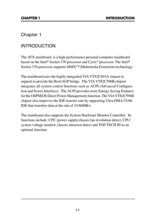
The ATX mainboard is a high-performance personal computer mainboard
based on the Intel® Socket 370 processor and Cyrix® processor. The Intel®
Socket 370 processor supports MMXTM (Multimedia Extension) technology.
The mainboard uses the highly integrated VIA VT82C693A chipset to
support to provide the Host/AGP bridge. The VIA VT82C596B chipset
integrates all system control functions such as ACPI (Advanced Configura-
tion and Power Interface). The ACPI provides more Energy Saving Features
for the OSPM(OS Direct Power Management) function. The VIA VT82C596B
chipset also improves the IDE transfer rate by supporting Ultra DMA/33/66
IDE that transfers data at the rate of 33/66MB/s.
The mainboard also supports the System Hardware Monitor Controller. Its
functions include: CPU /power supply/chassis fan revolution detect, CPU/
system voltage monitor, chassis intrusion detect and TOP TECH III as an
optional function.
1-1
�
CHAPTER 1
INTRODUCTION
1.1 Mainboard Features
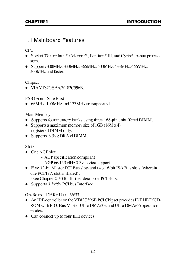
CPU
l Socket 370 for Intel® CeleronTM , Pentium® III, and Cyrix® Joshua proces-
sors.
l Supports 300MHz, 333MHz, 366MHz, 400MHz, 433MHz, 466MHz,
500MHz and faster.
Chipset
l VIA VT82C693A/VT82C596B.
FSB (Front Side Bus)
l 66MHz ,100MHz and 133MHz are supported.
Main Memory
l Supports four memory banks using three 168-pin unbuffered DIMM.
l Supports a maximum memory size of 1GB (16M x 4)
registered DIMM only.
l Supports 3.3v SDRAM DIMM.
Slots
l One AGP slot.
- AGP specification compliant
- AGP 66/133MHz 3.3v device support
l Five 32-bit Master PCI Bus slots and two 16-bit ISA Bus slots (wherein
one PCI/ISA slot is shared).
*See Chapter 2-30 for further details on PCI slots.
l Supports 3.3v/5v PCI bus Interface.
On-Board IDE for Ultra 66/33
l An IDE controller on the VT82C596B PCI Chipset provides IDE HDD/CD-
ROM with PIO, Bus Master Ultra DMA/33, and Ultra DMA/66 operation
modes.
l Can connect up to four IDE devices.
1-2
�
CHAPTER 1
INTRODUCTION
On-Board Peripherals
l On-Board Peripherals include:
- 1 floppy port supports 2 FDD with 360K, 720K, 1.2M, 1.44M and
2.88Mbytes.
- 2 serial port (COM A) + (COM B)
- 1 parallel port supports SPP/EPP/ECP mode
- 2 USB ports
- 1 IrDA connector for SIR.
BIOS
l The mainboard BIOS provides “Plug & Play” BIOS which detects the
peripheral devices and expansion cards of the board automatically.
l The mainboard provides a Desktop Management Interface(DMI) function
which records your mainboard specifications.
l ACPI(Advanced Configuration and Power Interface) feature.
l Anti-BIOS Virus function.
Dimension
l ATX Form Factor : 30cm(L) x 19.2cm(W) x 4 layers PCB
Mounting
l 6 mounting holes.
System Hardware Monitor
l CPU/Power Supply/Chassis Fan Revolution Detect
l CPU Fan Control detects the CPU temperature, then determine the FAN
SPEED, which utilizes PC Alert program (the fan will automatically stop
when the system enters suspend mode)
l System Voltage Detect
l 5VSB and Battery Voltage Detect
l CPU Overheat Warning.
l Display Actual Current Voltage
l Chassis Intrusion
1-3
�
CHAPTER 1
INTRODUCTION
Other Features
l Keyboard Password Wake-Up
l LAN Wake-Up
l Internal/External Modem Wake-Up
1-4
�
CHAPTER 1
INTRODUCTION
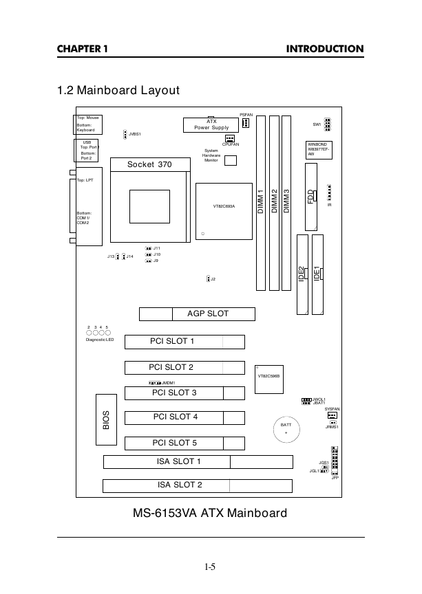
1.2 Mainboard Layout
Top: Mouse
Bottom:
Keyboard
USB
Top: Port 1
Bottom:
Port 2
Top: LPT
Bottom:
COM 1/
COM 2
PSFAN
ATX
Power Supply
CPUFAN
System
Hardware
Monitor
JVBS1
Socket 370
SW1
WINBOND
W83977EF-
AW
VT82C693A
1
M
M
D
I
2
M
M
D
I
3
M
M
D
I
D
D
F
IR
J13
J14
J11
J10
J9
J2
2
E
D
I
1
E
D
I
AGP SLOT
2 3 4 5
Diagnostic LED
S
O
B
I
PCI SLOT 1
PCI SLOT 2
JMDM1
PCI SLOT 3
PCI SLOT 4
PCI SLOT 5
ISA SLOT 1
ISA SLOT 2
VT82C596B
BATT
+
JWOL1
JBAT1
SYSFAN
JRMS1
JGS1
JGL1
JFP
MS-6153VA ATX Mainboard
1-5
�
CHAPTER 2
HARDWARE INSTALLATION
Chapter 2
HARDWARE INSTALLATION
2.1 Central Processing Unit: CPU
The mainboard operates with Intel® CeleronTM or Pentium® III processor.
The mainboard uses a CPU socket called Socket 370 for easy CPU installa-
tion. The CPU should always have a Heat Sink and a cooling fan attached to
prevent overheating.
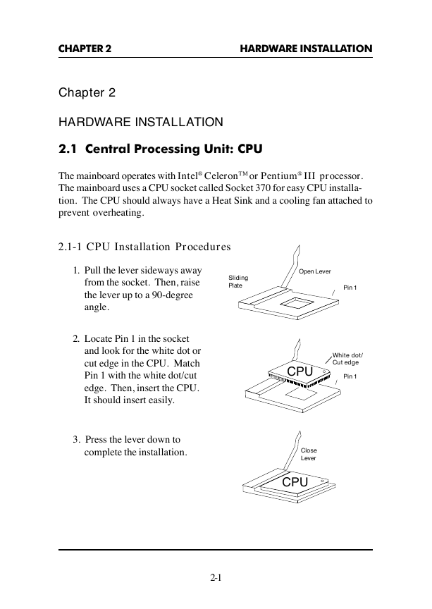
2.1-1 CPU Installation Procedures
1. Pull the lever sideways away
from the socket. Then, raise
the lever up to a 90-degree
angle.
2. Locate Pin 1 in the socket
and look for the white dot or
cut edge in the CPU. Match
Pin 1 with the white dot/cut
edge. Then, insert the CPU.
It should insert easily.
3. Press the lever down to
complete the installation.
Sliding
Plate
Open Lever
Pin 1
CPU
White dot/
Cut edge
Pin 1
Close
Lever
CPU
2-1
�
CHAPTER 2
HARDWARE INSTALLATION
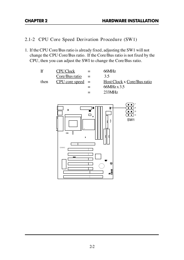
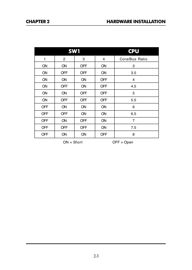
2.1-2 CPU Core Speed Derivation Procedure (SW1)
1. If the CPU Core/Bus ratio is already fixed, adjusting the SW1 will not
change the CPU Core/Bus ratio. If the Core/Bus ratio is not fixed by the
CPU, then you can adjust the SWI to change the Core/Bus ratio.
If
then
=
CPU Clock
Core/Bus ratio
=
CPU core speed =
=
=
66MHz
3.5
Host Clock x Core/Bus ratio
66MHz x 3.5
233MHz
1
2
3
4
SW1
2-2
�
###E###




 2023年江西萍乡中考道德与法治真题及答案.doc
 2012年重庆南川中考生物真题及答案.doc
 2013年江西师范大学地理学综合及文艺理论基础考研真题.doc
 2020年四川甘孜小升初语文真题及答案I卷.doc
 2020年注册岩土工程师专业基础考试真题及答案.doc
 2023-2024学年福建省厦门市九年级上学期数学月考试题及答案.doc
 2021-2022学年辽宁省沈阳市大东区九年级上学期语文期末试题及答案.doc
 2022-2023学年北京东城区初三第一学期物理期末试卷及答案.doc
 2018上半年江西教师资格初中地理学科知识与教学能力真题及答案.doc
 2012年河北国家公务员申论考试真题及答案-省级.doc
 2020-2021学年江苏省扬州市江都区邵樊片九年级上学期数学第一次质量检测试题及答案.doc
 2022下半年黑龙江教师资格证中学综合素质真题及答案.doc