HPE 3PAR StoreServ
Simulator
Changes to object, file, storage management
and reporting
Contents
HPE 3PAR StoreServ Simulator............................................................................................................2
Overview........................................................................................................................................................ 2
Supported Platform..................................................................................................................................2
Supported Features................................................................................................................................... 2
Simulator Installation................................................................................................................................2
Minimum System Requirements.......................................................................................................3
Installation and Configuration Summary...................................................................................3
VMware ESXi Server Installation......................................................................................................... 3
Installing the Cluster Nodes.................................................................................................................3
Installation of the Enclosure Node.................................................................................................. 4
Network Configuration...........................................................................................................................5
VMware Workstation................................................................................................................................... 6
Installation of the Cluster Nodes Overview................................................................................. 6
Enclosure Node Installation................................................................................................................ 7
Network Configuration using VMware Workstation............................................................... 7
Technical white paper
�
Technical white paper
Page 2
HPE 3PAR StoreServ Simulator
Overview
The 3PAR Simulator software provides a virtualized HPE 3PAR StoreServ Storage System without
the corresponding physical storage hardware requirements. The features normally provided by the
hardware components, including the ASIC, HBA and enclosure are emulated in software. The
3PAR Simulator provides the same look, feel and primary interaction capabilities of a physical
storage system including support for management, administration and reporting through the HP
3PAR StoreServ Management Console (SSMC), remote CLI, and client software access to the CIM-API
and WS-API interfaces.
Supported Platform
The 3PAR Simulator software release version 3.2.2 MU4 supports the configuration of up to 2
simultaneous instances, differentiated by name and serial number, of a 2-node HPE 3PAR
StoreServ 8200 Storage System running HP 3PAR OS version 3.2.2 MU4.
Supported Features
The following 3PAR StoreServ Storage System features are supported:
•
•
•
•
•
•
•
•
•
•
•
Up to 48 HDDs, 4 cage configuration
Cage types – DCN2, DCS7, DCS8
Disk types – FC, SSD, NL
3PAR Management Console support
CLI and Remote CLI support
CIM-API (SMI-S) and WS-API support
Storage Provisioning including Thin-Provisioning
Exporting Virtual Volumes
Adaptive Optimization (AO)
Dynamic Optimization (DO)
Local Replication (Snapshot)
Remote Replication (RCIP) - requires 2 instances of the simulator (Requires more resources)
Important to note – When using the HPE 3PAR Simulator with Remote Copy, extra resource requirements will be necessary for the VM’s which
make up the simulator instance.
NOTE: the license validity for HPE Storeserv 3PAR Simulator has been extended till
December 2024.
Simulator Installation
Installation of the HPE 3PAR simulator requires a VMware environment. Requirements include
One VMware VM assigned as the ESD node
Two VMware VM’s assigned as cluster node 1 and cluster node 2
�
Technical white paper
Page 3
Minimum System Requirements
The 3PAR Simulator requires a minimum of VMware ESXi 5.5 or above, or VMware Workstation 11 or later. The simulator configuration requires
deploying three VMs; two VMs simulating the cluster nodes, a third VM to simulate the enclosure and private network configuration to enable
communication between the three VMs. The simulator has not been tested on any other variations of virtual machines and it is not supported in
any other configuration that tested. It should be noted that the user can add additional resources but is not required unless simulating a RCIP
configuration as noted below.
The minimum system resources required for each VM are:
One virtual CPU (single core)
Three virtual NICs
2GB RAM (4GB is required for use in a RCIP configuration)
50GB disk space (full or thin-provisioned)
Installation and Configuration Summary
Setup of the 3PAR Simulator configuration will require completion of the following steps:
1.
2.
3.
4.
5.
Cluster Nodes Installation – Involves installation of two VMs (sim_node0 & sim_node1) using the cluster node OVF package.
Enclosure Node Installation – Involves installing one VM (sim_esd) using the enclosure node OVF package.
Network Configuration – Involves creating a private network for communication between the three VMs. The network configuration varies for the
VMware ESXi Server and VMware Workstation setup, follow the instructions in the corresponding section of this guide.
Simulator configuration and bring up – Involves configuration of the cluster node VMs, enclosure node VM and bringing them all up to form the
storage system simulator.
Installation of the HPE 3PAR StoreServ Management Console (SSMC) 2.3 and 3PAR CLI application v3.2.2 MU4 (optional).
VMware ESXi Server Installation
Installing the Cluster Nodes
The cluster node (clus_node) package is included in the HP-3PAR-StoreServ-Simulator-3.2.2MU4.zip file. Extract the files to a folder on your
computer. The uncompressed file size of the clus_node package is ~ 6.4GB
Note
Each "Deploy with OVF template" operation in vSphere Client can take up to 30 minutes to complete with high speed LAN networking. It is highly
recommended that the installation is performed from a high speed network or local disk.
The cluster node installation steps are as follows:
Step 1: Unzip the cluster node OVF package
There are 3 VM files in the cluster node OVF package:
•
clus_node_template_3.2.2.MU4_field_mode.ovf
•
clus_node_template_3.2.2.MU4_field_mode -disk1.vmdk
•
clus_node_template_3.2.2.MU4_field_mode.mf
Step 2: Create a VM (sim_node0) using the "Deploy OVF template" option in vSphere
•
•
Login to the VMware vSphere Client
Click the "File"option at the top menu
�
Technical white paper
Page 4
•
•
•
•
•
•
•
•
Click "DeployOVFtemplate"
In the "DeployfromafileorURL"dialog, specify the full pathname of the clus_node_template_3.2.2.MU4.ovffile
Click "Next"- shows the OVF Template details
Click "Next"- type in the name of the new VM
-
Example: sim_node0
Click "Next"- shows the disk format, choose thickor thinprovisioning
In “NetworkMapping”screen, select VMNetwork
Click "Next"- Ready to complete?
Click "Finish"- Deploying YournewVM
Step 3: Create a second VM (sim_node1) using the vCenter “clone” or “Deploy OVF template” option in vSphere
You can use the "clone" feature in vCenter to create an additional VM that is identical to the one that was created in Step 2 above, and provide a name
for the cloned VM (Example: sim_node1). If you are not using vCenter, you can create the second VM by following the steps below:
•
•
•
•
•
•
Login to the VMware vSphere Client
Click the "File"option at the top menu
Click "DeployOVFtemplate"
In the "DeployfromafileorURL"dialog, specify the full pathname of the clus_node_template_3.2.2.MU4_field_mode.ovffile
Click "Next"- shows the OVF Template details
Click "Next"- type in the name of the new VM
-
Example: sim_node1
•
•
•
•
Click "Next"- shows the disk format, choose thickor thinprovisioning
In “NetworkMapping”screen, select VMNetwork
Click "Next"- Ready to complete?
Click "Finish"- Deploying YournewVM
Installation of the Enclosure Node
The enclosure node (esd_node_template_3.2.2.MU4) OVF package is included in the HP-3PAR-StoreServ-Simulator-3.2.2 MU4.zip file. Extract the
files to a folder on your computer. The uncompressed file size of the enclosure node package is ~ 460MB.
Note
The enclosure node installation steps for creating the third VM (esd_node)are similar to the cluster node installation except that the
esd_node_template_3.2.2 MU4 OVF package must be used
Step 1: Unzip the enclosure node OVF package
There are 3 VM files in the enclosure node OVF package:
•
•
•
esd_node_template_3.2.2.MU4.ovf
esd_node_template_3.2.2.MU4 -disk1.vmdk
esd_node_template_3.2.2.MU4.mf
Step 2: Create VM (sim_esd)using the "Deploy OVF template" option
•
•
•
•
•
•
Login to the VMware vSphere Client
Click the "File"option at the top menu
Click "DeployOVFtemplate"
In "DeployfromafileorURL", specify the full pathname of the esd_node_template_3.2.2.MU4.ovffile
Click "Next"- shows the OVF Template details
Click "Next"- type in the name of the new VM
-
Example: sim_esd
•
Click "Next"- shows the disk format, choose thickor thinprovisioning
�
Technical white paper
Page 5
•
•
•
In “NetworkMapping”screen, pick VMNetwork
Click "Next"- Ready to complete?
Click "Finish"- Deploying YournewVM
Network Configuration
Once the VMs have been deployed, the network configuration must be completed to connect them to the appropriate networks. The VMs are
configured with three vNICs and the network label is set to VMNetworkby default for all the three vNICs. The default configuration must be changed
as follows:
•
The first vNIC will be dedicated for use with management tools. It must be connected to a network allowing communication to the servers
running the HP 3PAR Management Console, remote CLI or client software accessing the CIM-API (SMI-S) or WS-API. Once configured, these tools
will connect to the 3PAR Simulator via the cluster IP address specified during the “Out of the Box” (OOTB) procedure.
(Optional)The second vNIC will be dedicated for use by Remote Copy if you plan on configuring two separate instances of the 3PAR Simulator to
leverage this capability. If Remote Copy is configured this interface must be connected to the Remote Copy network. This applies only to the
cluster nodes (sim_node0 & sim_node1) as the enclosure node (sim_esd) is not part of the Remote Copy network. The second vNIC in the
enclosure node (sim_esd) is unused and the network label can be left to the default VMNetwork.
The third vNIC must be connected to a private network connecting all three VMs (sim_node0, sim_node1 & sim_esd) with a virtual switch
(vSwitch). The virtual switch should not be connected to a physical adapter as the traffic will only be routed locally (assuming the VMs hosted on
the same ESXi) to allow communication between the three VMs in the 3PAR Simulator configuration. Follow the instructions below in Step1:
vSwitchconfigurationand Step2:ConnectthethirdvNICineachVMtothePrivateNetworkto set up the private network.
•
•
Log in to the vSphere client and select your ESX host from the inventory panel
Click the “Configuration”tab in the right side top panel
Click on “Networking” in the Hardwareframe
Click on “AddNetworking”(toprightcorner)
Step 1: vSwitch configuration
To configure a vSwitch:
•
•
•
•
• Acceptthedefaultconnectiontype,“VirtualMachine”and click “Next”
•
•
•
Accept the default “CreateavSpherestandardswitch”
Deselect the network adapter(s).
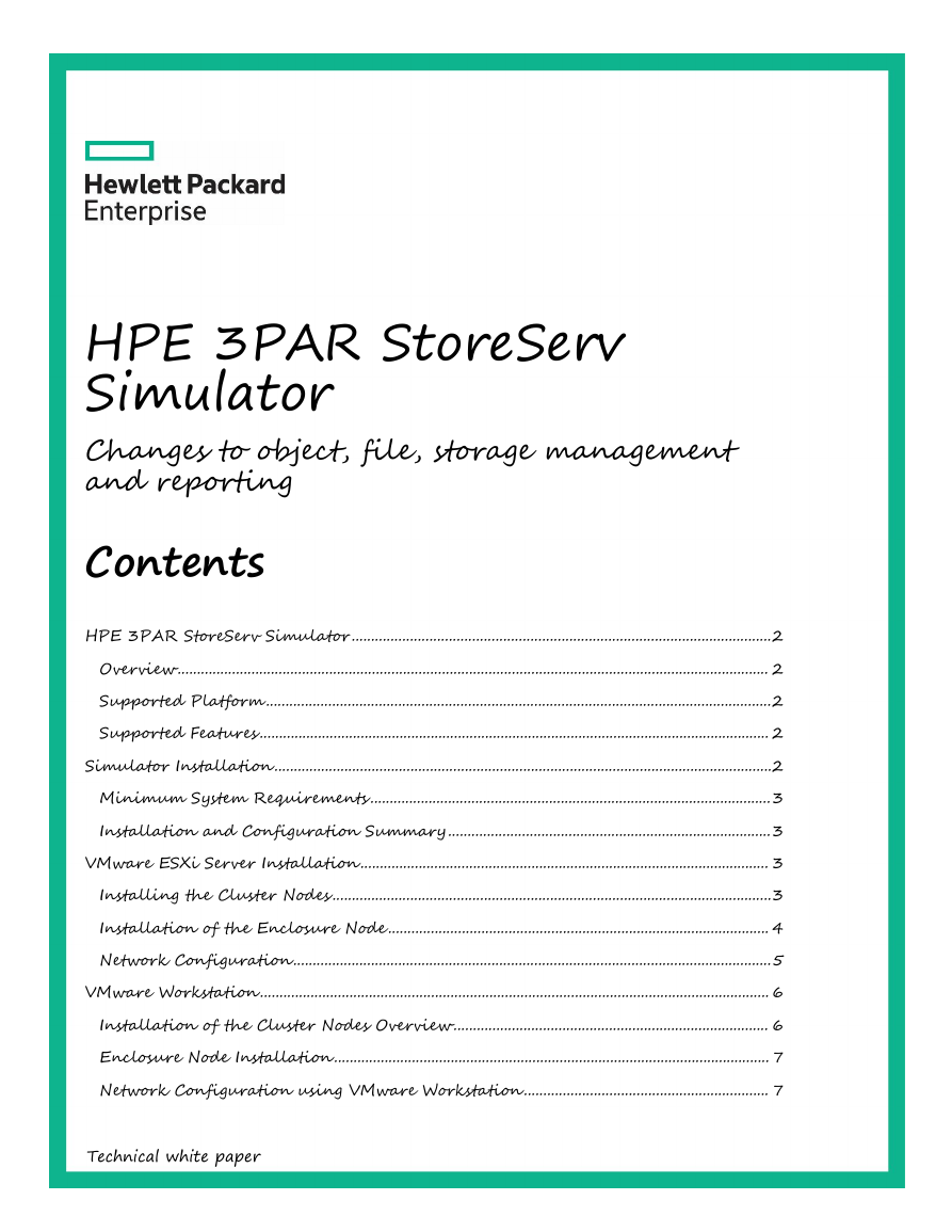
Example: If the adapter vmnic2is selected, deselect it. (See Figure 1 below)
Figure1SamplevSwitchconfigurationwithalladaptersunselected
•
•
•
Click “Next”
Accept the default Network Label and VLAN ID None (0). Make note of the Network Label, this label must be selected in the next step to connect
the vNIC to the correct network
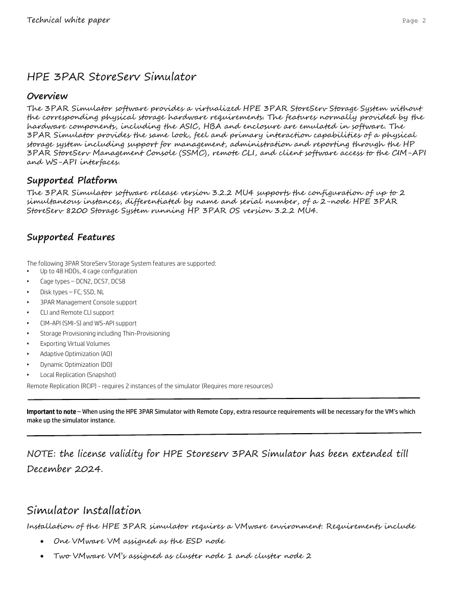
Click “Next”and then “Finish”to complete the vSwitch configuration (See Figure 2 below)
Figure2SamplevSwitchconfiguration
Step 2: Connect the third vNIC in each VM to the Private Network
Connect the third vNIC in each VM to the private network corresponding to the vSwitch created in the previous step.
To connect the vNIC:
•
Log in to the vSphere client and select the sim_esdVM from the inventory panel
�
Technical white paper
Page 6
•
•
•
•
•
•
Click the “GettingStarted”tab (in the right page)
Click on “Editvirtualmachinesettings”
Click on the network interface “NetworkAdapter3”.
In the Network label pull down menu, select the network label created in the previous step.
-
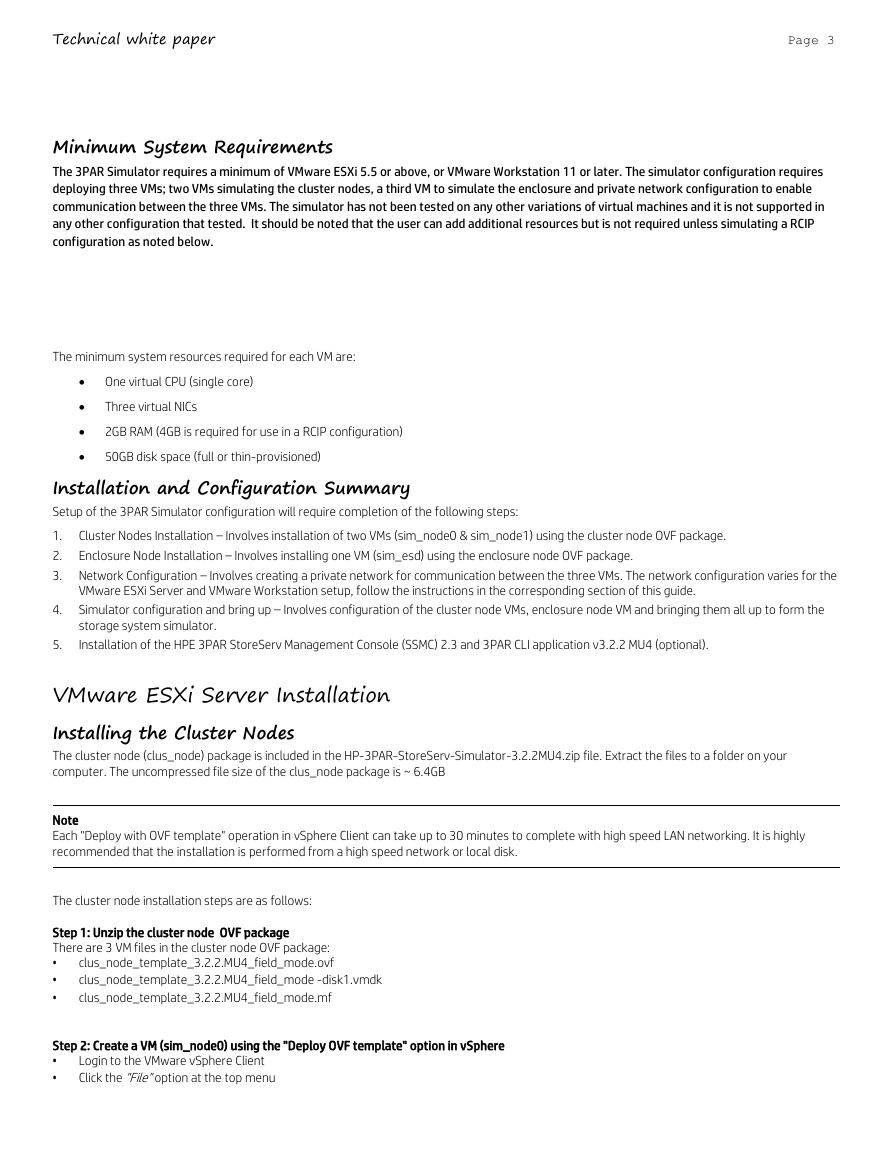
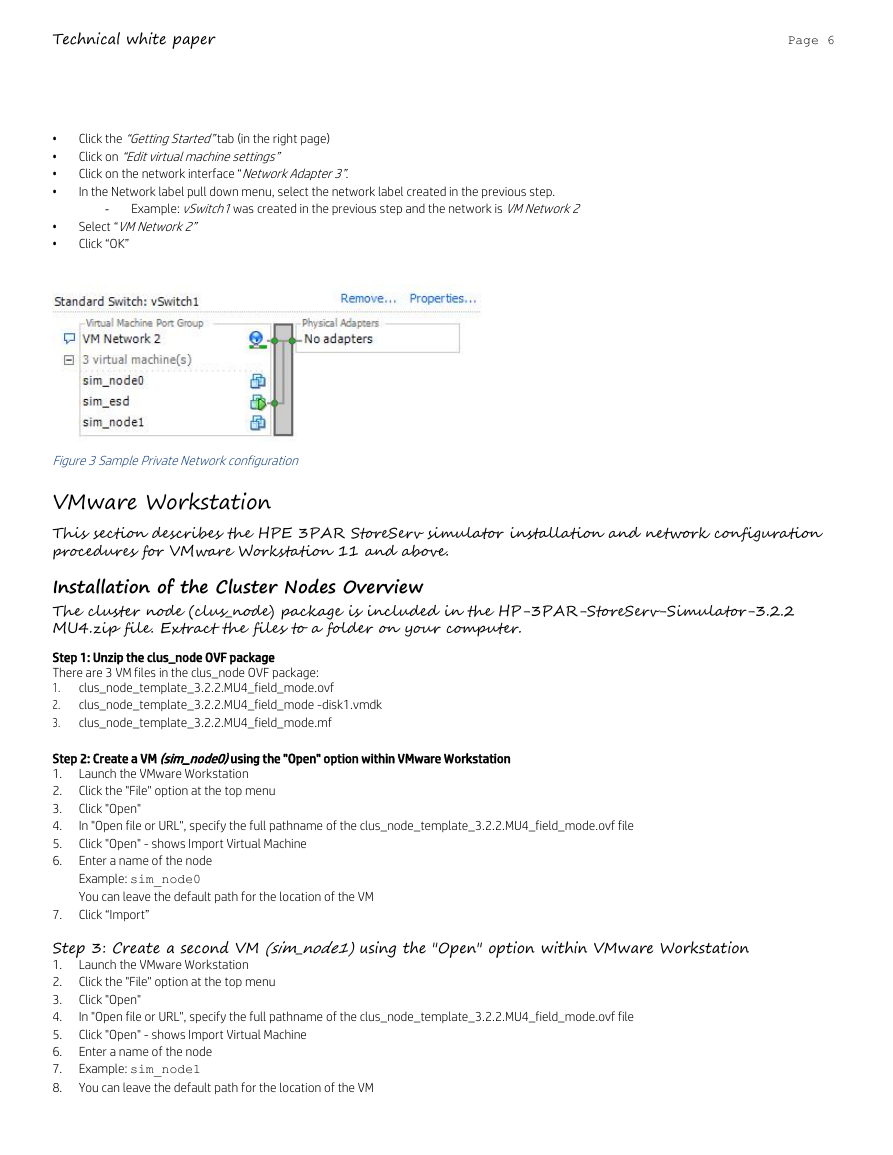
Example: vSwitch1was created in the previous step and the network is VMNetwork2
Select “VMNetwork2”
Click “OK”
Figure3SamplePrivateNetworkconfiguration
VMware Workstation
This section describes the HPE 3PAR StoreServ simulator installation and network configuration
procedures for VMware Workstation 11 and above.
Installation of the Cluster Nodes Overview
The cluster node (clus_node) package is included in the HP-3PAR-StoreServ-Simulator-3.2.2
MU4.zip file. Extract the files to a folder on your computer.
Step 1: Unzip the clus_node OVF package
There are 3 VM files in the clus_node OVF package:
1.
2.
3.
clus_node_template_3.2.2.MU4_field_mode.ovf
clus_node_template_3.2.2.MU4_field_mode -disk1.vmdk
clus_node_template_3.2.2.MU4_field_mode.mf
Step 2: Create a VM (sim_node0)using the "Open" option within VMware Workstation
1.
2.
3.
4.
5.
6.
Launch the VMware Workstation
Click the "File" option at the top menu
Click "Open"
In "Open file or URL", specify the full pathname of the clus_node_template_3.2.2.MU4_field_mode.ovf file
Click "Open" - shows Import Virtual Machine
Enter a name of the node
Example: sim_node0
You can leave the default path for the location of the VM
Click “Import”
7.
Step 3: Create a second VM (sim_node1)using the "Open" option within VMware Workstation
1.
2.
3.
4.
5.
6.
7.
8.
Launch the VMware Workstation
Click the "File" option at the top menu
Click "Open"
In "Open file or URL", specify the full pathname of the clus_node_template_3.2.2.MU4_field_mode.ovf file
Click "Open" - shows Import Virtual Machine
Enter a name of the node
Example: sim_node1
You can leave the default path for the location of the VM
�
Technical white paper
Page 7
9.
Click “Import”
Enclosure Node Installation
Step 1: Create a VM (sim_esd)using the "Open" option within VMware Workstation
1.
2.
3.
4.
5.
Click the "File" option at the top menu
Click "Open"
In "Open file or URL", specify the full pathname of the esd_node_template_3.2.2.MU4.ovf file
Click "Open" - shows Import Virtual Machine
Enter a name of the node
Example: esd_node
You can leave the default path for the location of the VM
Click “Import”
6.
Network Configuration using VMware Workstation
Once the VMs are deployed, the network configuration must be done to connect them to appropriate networks. The VMs are configured with three
vNICs and the network label is set to VMNetworkby default for all the three vNICs. The configuration must be changed as follows:
•
The first vNIC (Network Adapter in figure 4) will be dedicated for use with management tools. It must be connected to a network allowing
communication to the servers running the HP 3PAR StoreServ Management Console, remote CLI or client software accessing the CIM-API (SMI-S)
or WS-API. Once configured, these tools will connect to the 3PAR Simulator via the cluster IP address specified during the “Out of the Box” (OOTB)
procedure.
(Optional)The second vNIC (Network Adapter 2 in figure 4) will be dedicated for use by Remote Copy if you plan on configuring two
separate instances of the 3PAR Simulator to leverage this capability. If Remote Copy is configured this interface must be connected to the
Remote Copy network. This applies only to the cluster nodes (sim_node0 & sim_node1) as the enclosure node (sim_esd) is not part of the
Remote Copy network. The second vNIC in the enclosure node (sim_esd) is unused and the network label can be left to the default VMNetwork.
The third vNIC (Network Adapter3 in figure 4) must be connected to a private network connecting all three VMs (sim_node0, sim_node1 &
sim_esd) with a Lan Segment for traffic to be routed locally, allowing communication between the three VMs in the 3PAR Simulator configuration.
Follow the instructions below in Step1:ConfiguringaLANSegmentand connectingvNICtotheLANSegmentNetworkto set up the private
network.
•
•
Step 1: Configuring a LAN Segment
To configure a LAN Segment:
Launch VMware Workstation
1.
Right-Click on sim_esd, select “Settings”
2.
3.
Click on “Networking Adapter 3” in the Hardwareframe
4. In the Network Connection frame, select LAN Segment
5.
6.
Click on the tab below that says “LANsegment”.A global LAN Segments Window will pop up
Click “Add” and enter a name for the LAN Segment
Example: Simulator
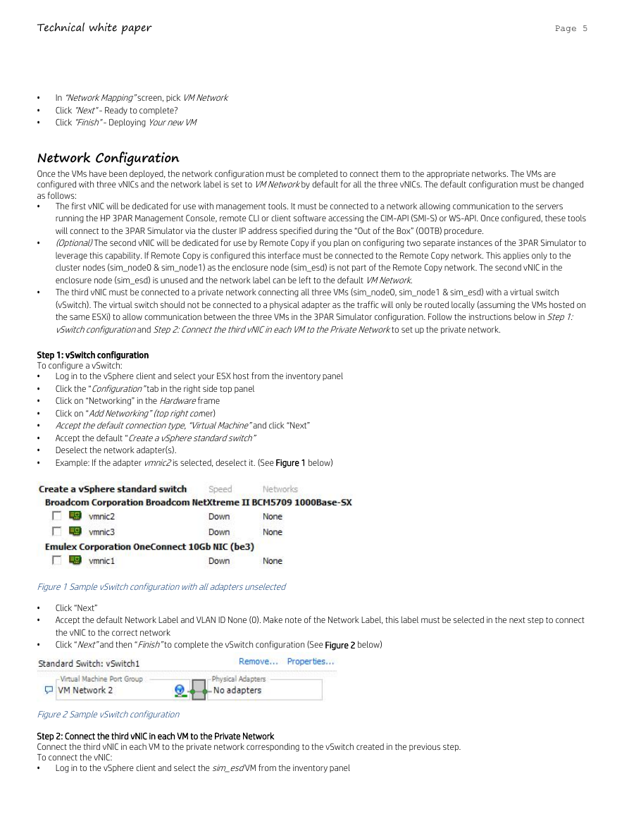
Ensure that the Network Adapter 3 is connected to the LAN Segment you just created by selecting it using the drop down menu (See Figure 4
below)
Click “OK”
7.
8.
�
Technical white paper
Page 8
Figure4VirtualMachineSettings-LANsegmentselectionforNetworkAdaptor3
Important
Repeat the above steps to connect Network Adapter 3 for both sim_node0 & sim_node1 to the LAN segment
Step 2: Configuring a management network.
In order to use the HP 3PAR StoreServ Management Console or 3PAR remote CLI on the system that is running VMware Workstation and hosting the
3PAR Simulator instance, or another VM instance you will need to configure Network Adapter 1.
Right-Click on sim_node0, select “Settings”
Click on “NetworkAdapter”in the Hardwareframe
1.
2.
3. In the Networkconnection frame, select “Host-only”
4.
5.
6.
7.
8. Note the Subnet Address and the Subnet Mask. You will need this later during the OOTB process when configuring the node IP address that
Click “OK”
Click the "Edit"option at the top menu
Click "VirtualNetworkEditor”
Select the host only type VMnet
9.
talks to the StoreServ Management Console, CLI Utility, Putty, etc.
After creating the “Host Only Network” you may need to reboot your machine in order to initialize the network stack. Few users running VMware
Workstation 10 have reported that is the only way they could get the network to work in their case.
�



 2023年江西萍乡中考道德与法治真题及答案.doc
 2012年重庆南川中考生物真题及答案.doc
 2013年江西师范大学地理学综合及文艺理论基础考研真题.doc
 2020年四川甘孜小升初语文真题及答案I卷.doc
 2020年注册岩土工程师专业基础考试真题及答案.doc
 2023-2024学年福建省厦门市九年级上学期数学月考试题及答案.doc
 2021-2022学年辽宁省沈阳市大东区九年级上学期语文期末试题及答案.doc
 2022-2023学年北京东城区初三第一学期物理期末试卷及答案.doc
 2018上半年江西教师资格初中地理学科知识与教学能力真题及答案.doc
 2012年河北国家公务员申论考试真题及答案-省级.doc
 2020-2021学年江苏省扬州市江都区邵樊片九年级上学期数学第一次质量检测试题及答案.doc
 2022下半年黑龙江教师资格证中学综合素质真题及答案.doc