UNIVERSITÀ DEGLI STUDI DI PADOVA
DIPARTIMENTO DI TECNICA E GESTIONE DEI SISTEMI
CORSO DI LAUREA MAGISTRALE IN INGEGNERIA
INDUSTRIALI
MECCATRONICA
TESI DI LAUREA MAGISTRALE
Software in C++ for communication
between CAN bus and ROS in a robot
vehicle
Relatore: Monica Reggiani
Correlatore: Sami Terho, Aalto University - Finland
Laureando: Alex Battiston
1034764-IMC
ANNO ACCADEMICO: 2014-15
�
S U M M A R Y
The project has the aim to develop a C++ software for a robot vehicle in a
real time system for management the communication between the CAN bus
and ROS. During development test measure the efficacy, in terms of time and
messages exchanged, several versions of software to test the communication
via CAN bus the libraries provided by the PC manufacturer. In addition, it has
also been tested software solutions that use, with different combinations, mu-
tex and condition variables during the phases of sending and receiving. From
the analysis of the experiments it has been found that, for this architecture, the
most efficiently communication via CAN bus has been obtained using mutex
and condition variables during the sending of the CAN message.
.
W O R D S O F T H A N K S
Dedicated to my mom.
�
C O N T E N T S
introduction
1
2 autonomous vehicles
4 hardware
.
5.1 ROS .
5 communication
.
.
5.1.1 Topic .
5.2 Service .
.
5.3 CAN library .
.
.
.
.
.
3 can bus and j1939
.
.
.
.
.
.
.
.
.
.
3.5
.
.
ID .
. . . . . . .
3.4 Technology .
. . . . . . . . . . . . . . . . . . . . . . . . . . . . . .
Introduction .
.
.
.
.
.
5
7
2.1
7
. . . . . . . . . . . . . . . . . . . . . . . . . . . . . .
2.2 Levels .
7
.
.
.
. . . . . . .
. . . . . . . . . . . . . . . . . . . . . . .
2.3 History .
8
.
.
. . . . . . . . . . . . . . . . . . . . . . .
. . . . . . .
2.4 Research .
. . . . . . . . . . . . . . . . . . . . . . . 10
.
. . . . . . .
2.5 Benefits .
. . . . . . . . . . . . . . . . . . . . . . . . . . . . 10
.
.
.
2.6 Technology .
11
. . . . . . . . . . . . . . . . . . . . . . . . . . . . . .
2.7 Estimated cost . . . . . . . . . . . . . . . . . . . . . . . . . . . . . . 14
2.8 Transform car in autonomous vehicle . . . . . . . . . . . . . . . . 14
2.9 ATV .
. . . . . . . . . . . . . . . . . . . . . . . . . . . . 14
17
3.1 Controller area network (CAN) . . . . . . . . . . . . . . . . . . . . 17
3.2 Features of CAN . . . . . . . . . . . . . . . . . . . . . . . . . . . . 17
3.3
. . . . . . . . . . . . . . . . . . . . . . . 19
ISO layers
3.3.1 Physical layer . . . . . . . . . . . . . . . . . . . . . . . . . . 19
. . . . . . . . . . . . . . . . . . . . . . . . . 20
3.3.2 Data-link layer
21
3.4.1 Types of Frames . . . . . . . . . . . . . . . . . . . . . . . . . 22
J1939 .
. . . . . . . . . . . . . . . . . . . 23
. . . . . . . . . . .
3.5.1
. . . . . . . . . . . . . . . . . . . . . . . . . . . . . . 23
3.5.2 Group Number . . . . . . . . . . . . . . . . . . . . . . . . . 26
3.6 ATV’s CAN architecture . . . . . . . . . . . . . . . . . . . . . . . . 27
29
. . . . . . . . . . . . . . . . . . . . . . . . . . . . . . 29
. . . . . . . . . . . . . . . . . . . . . . . . . . . . . . 29
4.2.1 Angle of steering . . . . . . . . . . . . . . . . . . . . . . . . 29
. . . . . . . . . . . . . . . . . . . . . . . . . . . . . . 29
4.2.2
Speed .
4.3 Control Unit .
. . . . . . . . . . . . . . . . . . . . . . . . . . . . . . 30
4.4 Embedded system . . . . . . . . . . . . . . . . . . . . . . . . . . . . 30
31
4.5 LiDAR .
. . . . . . . . . . . . . . . . . . . . . . . . . . . . . .
4.6 Bumblebees XB3 . . . . . . . . . . . . . . . . . . . . . . . . . . . . .
31
4.7 Kvaser Leaf Light HS . . . . . . . . . . . . . . . . . . . . . . . . . . 33
4.8 Network architecture . . . . . . . . . . . . . . . . . . . . . . . . . . 33
35
. . . . . . . . . . . . . . . . . . . . . . . . . . . . . . 35
. . . . . . . . . . . . . . . . . . . . . . . . . . . . . . 35
. . . . . . . . . . . . . . . . . . . . . . . . . . . . . . 37
. . . . . . . . . . . . . . . . . . . . . . . . . . . . . . 37
. . . . . . . . . . . . . . . . . . . . . 37
sendCanMessage . . . . . . . . . . . . . . . . . . . . . . . . 38
getCanMessage . . . . . . . . . . . . . . . . . . . . . . . . . 38
5.3.1 CAN message format
5.3.2
5.3.3
4.1 Vehicle .
4.2 Sensor
.
.
.
.
.
.
.
.
.
.
.
.
.
.
3
�
6
7
.
.
.
.
.
.
.
.
.
.
.
.
.
.
.
.
.
.
.
.
.
.
.
.
.
.
.
.
.
.
.
5.4 Ackermann .
implementation
6.1
. .
. . . . . . . . . . . . . . . . . . . . . . .
Introduction .
.
6.2
. . . . . . . . . . . . . . . . . . . . . . . . .
startCommunication .
6.3
. . . . . . . . . . . . . . . . . . . . . . . . .
.
communication .
6.4 CAN.cpp .
. .
.
.
6.5 CAN.h .
.
.
.
.
.
6.6 parameterCar.h .
. .
.
6.7 CANsimulator.exe
. .
.
experiments and results
7.1 Experiments .
.
7.2 Groups .
.
.
7.3 Codes and versions .
7.4 Results .
.
8 conclusion
Appendix a communication
. .
. . . . . . . . . . . . . . . . . . . . . . . . . 38
5.4.1 Ackermann geometry . . . . . . . . . . . . . . . . . . . . . 38
5.4.2 AckermannDrive Message . . . . . . . . . . . . . . . . . . . 39
41
41
41
41
. . . . . . . . . . . . . . . . . . . . . . . 42
. . . . . . . . . . . . . . . . . . . . . . . 42
. . . . . . . . . . . . . . . . . . . . . . . 42
. . . . . . . . . . . . . . . . . . . . . . . 42
45
. . . . . . . . . . . . . . . . . . . . . . . . . 45
. . . . . . . . . . . . . . . . . . . . . . . 45
.
. . . . . . . . . . . . . . . . . . . . . . . . . 46
. . . . . . . . . . . . . . . . . . . . . . . 49
. .
53
55
a.1 CAN library .
. . . . . . . . . . . . . . . . . . . . . . . 55
a.2 AckermannDrive Message . . . . . . . . . . . . . . . . . . . . . . . 56
57
. . . . . . . . . . . . . . . . . . . . . . . 57
. .
. . . . . . . . . . . . . . . . . . . . . . . . . 59
Appendix c codes and versions
63
Appendix d implementation
67
d.1 startCommunication.cpp .
. . . . . . . . . . . . . . . . . . . . . . . 67
d.2 communication .
. . . . . . . . . . . . . . . . . . . . . . . 69
.
.
.
d.3 ./CAN.cpp .
. . . . . . . . . . . . . . . . . . . . . . . 69
. .
.
.
d.4 ./CAN.h .
. . . . . . . . . . . . . . . . . . . . . . . 75
.
.
. .
.
. . . . . . . . . . . . . . . . . . . . . . . . . 77
d.5 ./parameterCar.h .
Appendix e user guide
79
Appendix b ros
b.1 Topic .
.
b.2 Service .
.
.
.
.
.
.
.
.
.
.
.
.
.
.
.
.
.
.
.
.
.
.
.
.
.
.
.
.
.
.
.
.
.
.
.
.
.
.
.
.
.
.
.
.
.
.
4
�
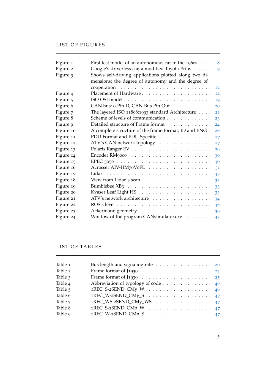
L I S T O F F I G U R E S
Figure 1
Figure 2
Figure 3
Figure 4
Figure 5
Figure 6
Figure 7
Figure 8
Figure 9
Figure 10
Figure 11
Figure 12
Figure 13
Figure 14
Figure 15
Figure 16
Figure 17
Figure 18
Figure 19
Figure 20
Figure 21
Figure 22
Figure 23
Figure 24
8
9
First test model of an autonomous car in the 1960s . . . .
Google’s driverless car, a modified Toyota Prius . . . . .
Shows self-driving applications plotted along two di-
mensions: the degree of autonomy and the degree of
cooperation . . . . . . . . . . . . . . . . . . . . . . . . . . 12
Placement of Hardware . . . . . . . . . . . . . . . . . . . . 12
ISO OSI model . . . . . . . . . . . . . . . . . . . . . . . . . 19
. . . . . . . . . . . 20
CAN bus: 9-Pin D, CAN Bus Pin Out
The layered ISO 11898:1993 standard Architecture . . . .
21
Scheme of levels of communication . . . . . . . . . . . . . 23
. . . . . . . . . . . . 24
Detailed structure of Frame format
A complete structure of the frame format, ID and PNG . 26
PDU Format and PDU Specific . . . . . . . . . . . . . . . 27
ATV’s CAN network topology . . . . . . . . . . . . . . . 27
Polaris Ranger EV . . . . . . . . . . . . . . . . . . . . . . . 29
Encoder RM9000 . . . . . . . . . . . . . . . . . . . . . . . 30
EPEC 5050 . . . . . . . . . . . . . . . . . . . . . . . . . . . 30
Acrosser AIV-HM76V0FL . . . . . . . . . . . . . . . . . .
31
. . . . . . . . . . . . . . . . . . . . . . . . . . . . . . 32
Lidar
View from Lidar’s scan . . . . . . . . . . . . . . . . . . . . 32
Bumblebee XB3 . . . . . . . . . . . . . . . . . . . . . . . . 33
Kvaser Leaf Light HS . . . . . . . . . . . . . . . . . . . . . 33
ATV’s network architecture . . . . . . . . . . . . . . . . . 34
ROS’s level . . . . . . . . . . . . . . . . . . . . . . . . . . . 36
Ackermann geometry . . . . . . . . . . . . . . . . . . . . . 39
Window of the program CANsimulator.exe . . . . . . . . 43
L I S T O F TA B L E S
Table 1
Table 2
Table 3
Table 4
Table 5
Table 6
Table 7
Table 8
Table 9
Bus length and signaling rate . . . . . . . . . . . . . . . . 20
Frame format of J1939 . . . . . . . . . . . . . . . . . . . . 24
Frame format of J1939 . . . . . . . . . . . . . . . . . . . . 25
Abbreviation of typology of code . . . . . . . . . . . . . . 46
1REC_S-2SEND_CMy_W . . . . . . . . . . . . . . . . . . . 46
1REC_W-2SEND_CMy_S . . . . . . . . . . . . . . . . . . . 47
1REC_WS-2SEND_CMy_WS . . . . .
. . . . . . . . . . . 47
1REC_S-2SEND_CMn_W . . . . . . . . . . . . . . . . . . 47
1REC_W-2SEND_CMn_S . . . . . . . . . . . . . . . . . . . 47
5
�
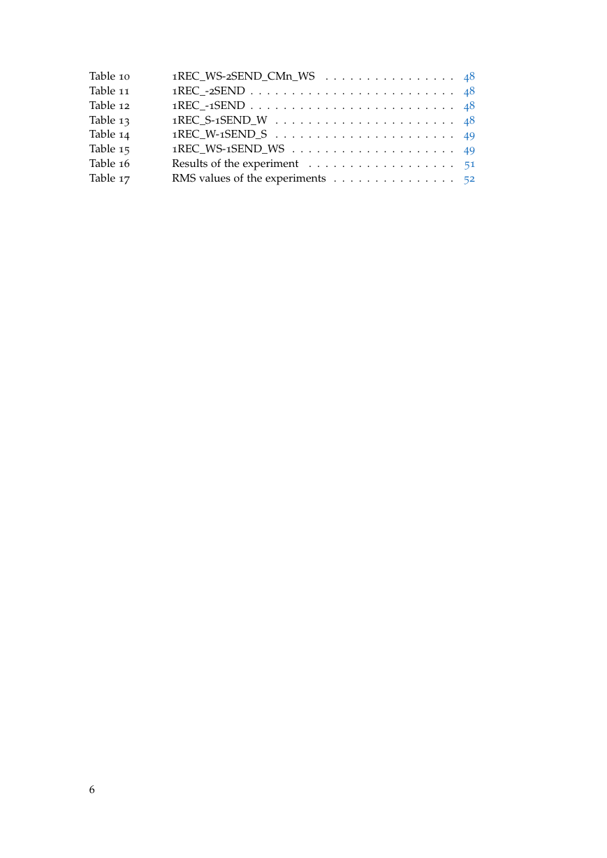
Table 10
Table 11
Table 12
Table 13
Table 14
Table 15
Table 16
Table 17
1REC_WS-2SEND_CMn_WS . . . . . . . . . . . . . . . . 48
1REC_-2SEND . . . . . . . . . . . . . . . . . . . . . . . . . 48
1REC_-1SEND . . . . . . . . . . . . . . . . . . . . . . . . . 48
1REC_S-1SEND_W . . . . . . . . . . . . . . . . . . . . . . 48
1REC_W-1SEND_S . . . . . . . . . . . . . . . . . . . . . . 49
1REC_WS-1SEND_WS . . . . . . . . . . . . . . . . . . . . 49
51
Results of the experiment
RMS values of the experiments . . . . . . . . . . . . . . . 52
. . . . . . . . . . . . . . . . . .
6
�
1
I N T R O D U C T I O N
Autonomous vehicle is capable of sensing its environment and navigating
without human input and the ATV (all terrain vehicle) project has transformed
an electronic four-wheel vehicle in a robot which, autonomously, is able to fol-
low a person who walks in front of it and drive by itself without the human
control [1][2]. The motivation behind this idea is to help a person to carry peo-
ple or carriage transportation, may it be luggage, boxes, groceries, etc. This
idea also proves to be very useful for handicap/disabled applications, or also
for driving the vehicle with a remote control like smartphone. This work is
a part of the ATV project to equip with sensors and actuators which enable
the higher level system to control ATV’s motions and therefore enable two
autonomous main actions: follow a user and avoid obstacles in real time in
outdoor environment. In order for the autonomous vehicle to achieve these
features, the system is implemented with a combination of computer vision,
distance sensors and controls software algorithm.
The aim of this thesis is to develop the C++ code written for the robot car with
the purpose of interfacing the communication between the CAN bus with
odometry-based motion measurement and localisation, and the software for
planning trajectory via ROS.
Data detected from car’s sensor are sent through the interface of this software
to planning controller trajectory layer which generates a path and sends the
information of angle of steering and speed to the vehicle.
The overview of autonomous vehicles has been done in the first chapter where
it is defined the robot car, its history of the past, present and the future of them,
the technology and benefits. The chapter number two introduce and describe
in detail the CAN bus and the protocol J1939, both adopted for this project.
Entering into the project, the hardware chapter describes the components of
the vehicle that allow the car to be autonomous. The fourth chapter focus on
the software used, it explains the communication with ROS framework and an-
alyzes and exposes the libraries used for developing the communication with
the CAN bus and the tools used in the ROS frameworks, in addition in this
chapter is discussed the geometry of the car involves the use of the geometry
of Ackerman. The developed software is described in the fifth chapter. The
experiments and the results obtained for developing the software are exposed
in the 6th chapter and different versions of the software have been tested for
discover which version allows the best management of communication. The
experiments investigates whether the presence of condition variables produce
positive or negative effects. The conclusion of the experiments are in the sev-
enth and last chapter and concludes that the presence of variable conditions,
for this system, allow a good performance of exchanging messages in the pres-
ence of them only in the functions of sending message with the CAN bus.
7
�
�


 2023年江西萍乡中考道德与法治真题及答案.doc
 2012年重庆南川中考生物真题及答案.doc
 2013年江西师范大学地理学综合及文艺理论基础考研真题.doc
 2020年四川甘孜小升初语文真题及答案I卷.doc
 2020年注册岩土工程师专业基础考试真题及答案.doc
 2023-2024学年福建省厦门市九年级上学期数学月考试题及答案.doc
 2021-2022学年辽宁省沈阳市大东区九年级上学期语文期末试题及答案.doc
 2022-2023学年北京东城区初三第一学期物理期末试卷及答案.doc
 2018上半年江西教师资格初中地理学科知识与教学能力真题及答案.doc
 2012年河北国家公务员申论考试真题及答案-省级.doc
 2020-2021学年江苏省扬州市江都区邵樊片九年级上学期数学第一次质量检测试题及答案.doc
 2022下半年黑龙江教师资格证中学综合素质真题及答案.doc