Abstract
引言
1.1 FPGA发展历程
1.2 VHDL语言介绍
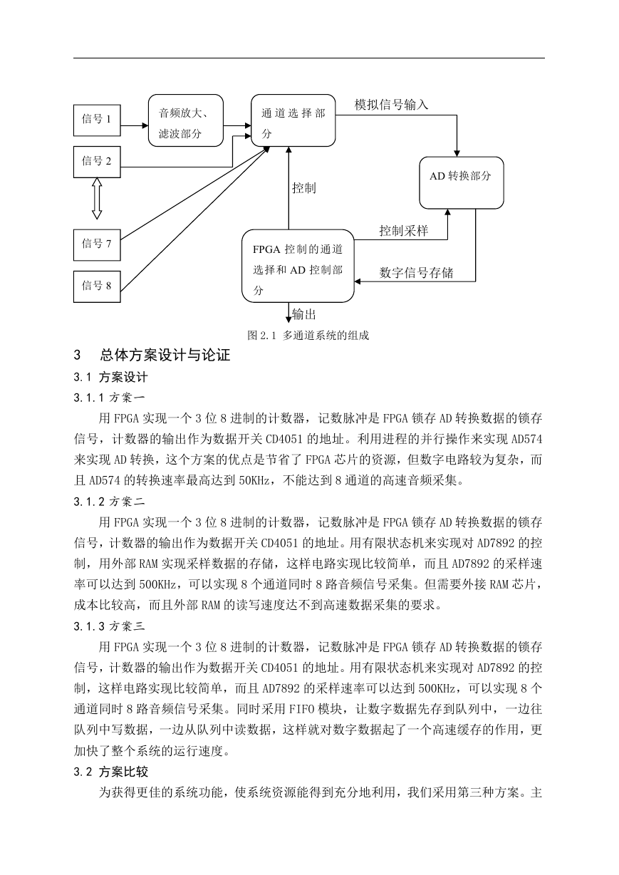
2 多通道采样系统的组成
3 总体方案设计与论证
3.1 方案设计
3.1.1方案一
3.1.2方案二
3.1.3方案三
3.2 方案比较
4 单元电路的设计
4.1 音频放大、滤波部分
4.1.1音频放大部分
4.1.2有源滤波器的设计
4.2 AD采样电路
4.2.1芯片介绍
4.2.2芯片应用
4.3 FPGA控制部分
4.3.1通道选择模块
4.3.2AD7892控制部分
4.3.3延时模块的设计
4.3.4串并输出选择控制
4.3.5FIFO模块
4.4 FPGA的硬件设计
4.4.1EP1K30TC144-3芯片介绍
4.4.2芯片组成描述
4.4.3芯片工作电压设计
4.4.4芯片配置介绍
4.4.5电路设计注意事项
4.4.6硬件电路设计技巧
5 软件介绍
5.1 MAX+PlusⅡ
5.2 Electronics Workbench(EWB)
6 整机调试
7 结论
谢 辞
参考文献
附 录
1 各模块程序
(1)通道选择模块
library ieee;
use ieee.std_logic_1164.all;
use ieee.std_logic_unsigned.all;
entity count is
port(clk:in std_logic;
--cnt:out integer range 0 to 7;
cnt : out std_logic_vector(2 downto 0));
--oc : out std_logic);
end count;
architecture archcount of count is
signal q:std_logic_vector(2 downto 0);
begin
counter:process(clk)
begin
if(clk'event and clk='1') then
if q="111" then
q<="000";--oc<='1';
else
q<=q+1;--oc<='0';
end if;
end if;
cnt<=q;
end process;
end archcount;
(2)延时模块
library ieee;
use ieee.std_logic_1164.all;
entity delay is
port(in1,in2,in3:in std_logic;
out1,out2,out3:out std_logic);
end delay;
architecture behav of delay is
signal comin:std_logic_vector(2 downto 0);
signal comout:std_logic_vector(2 downto 0);
begin
process(in1,in2,in3)
begin
comin<=in3&in2&in1;
case comin is
when "000"=> comout<="111";
when "001"=> comout<="000";
when "010"=> comout<="001";
when "011"=> comout<="010";
when "100"=> comout<="011";
when "101"=> comout<="100";
when "110"=> comout<="101";
when "111"=> comout<="110";
when others=>comout<="ZZZ";
end case;
out1<=comout(0);out2<=comout(1);out3<=comout(2);
end process;
end behav;
(3)AD采样控制模块
library ieee;
use ieee.std_logic_1164.all;
entity adcontrol is
port(D : in std_logic_vector(11 downto 0);
clk,eoc : in std_logic;
b0,b1,b2:in std_logic;
wr_en,rd_en : out std_logic;
lock0,conv,rd,cs: out std_logic;
Q : out std_logic_vector(15 downto 0))
end entity;
architecture behav of adcontrol is
type states is(st1,st2,st3,st4,st5,st6,st7,st8);
signal current_state,next_state:states:=st1;
signal regl1 : std_logic_vector(11 downto 0);
signal regl : std_logic_vector(15 downto 0);
signal lock : std_logic;
begin
lock0 <= lock;
end behav;
(4)串并转换模块部分程序
library ieee;
use ieee.std_logic_1164.all;
use ieee.std_logic_unsigned.all;
entity counter4 is
port(clk:in std_logic;
cnt4 : out std_logic_vector(3 downto 0)
);
end counter4;
architecture archcount of counter4 is
signal q:std_logic_vector(3 downto 0);
begin
counter:process(clk)
begin
if(clk'event and clk='1') then
if q="1111" then
q<="0000";
else
q<=q+1;
end if;
end if;
cnt4<=q;
end process;
end archcount;
2 FPGA顶层设计图
3 电路设计图
(1)音频放大
(2)滤波器
(3)AD7892电路
FPGA芯片PCB图



 2023年江西萍乡中考道德与法治真题及答案.doc
 2012年重庆南川中考生物真题及答案.doc
 2013年江西师范大学地理学综合及文艺理论基础考研真题.doc
 2020年四川甘孜小升初语文真题及答案I卷.doc
 2020年注册岩土工程师专业基础考试真题及答案.doc
 2023-2024学年福建省厦门市九年级上学期数学月考试题及答案.doc
 2021-2022学年辽宁省沈阳市大东区九年级上学期语文期末试题及答案.doc
 2022-2023学年北京东城区初三第一学期物理期末试卷及答案.doc
 2018上半年江西教师资格初中地理学科知识与教学能力真题及答案.doc
 2012年河北国家公务员申论考试真题及答案-省级.doc
 2020-2021学年江苏省扬州市江都区邵樊片九年级上学期数学第一次质量检测试题及答案.doc
 2022下半年黑龙江教师资格证中学综合素质真题及答案.doc