2Gb: x4, x8, x16 DDR3 SDRAM
Features
DDR3 SDRAM
MT41J512M4 – 64 Meg x 4 x 8 Banks
MT41J256M8 – 32 Meg x 8 x 8 Banks
MT41J128M16 – 16 Meg x 16 x 8 Banks
Features
• VDD = VDDQ = 1.5V ±0.075V
• 1.5V center-terminated push/pull I/O
• Differential bidirectional data strobe
• 8n-bit prefetch architecture
• Differential clock inputs (CK, CK#)
• 8 internal banks
• Nominal and dynamic on-die termination (ODT)
for data, strobe, and mask signals
• Programmable CAS READ latency (CL)
• Posted CAS additive latency (AL)
• Programmable CAS WRITE latency (CWL) based on
tCK
• Fixed burst length (BL) of 8 and burst chop (BC) of 4
(via the mode register set [MRS])
• Selectable BC4 or BL8 on-the-fly (OTF)
• Self refresh mode
• TC of 0°C to 95°C
– 64ms, 8192 cycle refresh at 0°C to 85°C
– 32ms, 8192 cycle refresh at 85°C to 95°C
• Self refresh temperature (SRT)
• Automatic self refresh (ASR)
• Write leveling
• Multipurpose register
• Output driver calibration
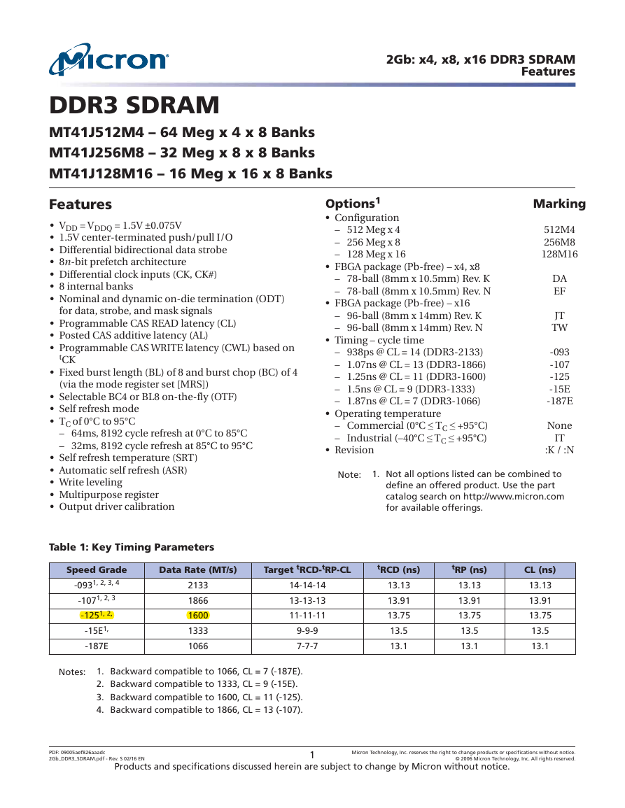
Table 1: Key Timing Parameters
Options1
• Configuration
– 512 Meg x 4
– 256 Meg x 8
– 128 Meg x 16
• FBGA package (Pb-free) – x4, x8
– 78-ball (8mm x 10.5mm) Rev. K
– 78-ball (8mm x 10.5mm) Rev. N
• FBGA package (Pb-free) – x16
– 96-ball (8mm x 14mm) Rev. K
– 96-ball (8mm x 14mm) Rev. N
• Timing – cycle time
– 938ps @ CL = 14 (DDR3-2133)
– 1.07ns @ CL = 13 (DDR3-1866)
– 1.25ns @ CL = 11 (DDR3-1600)
– 1.5ns @ CL = 9 (DDR3-1333)
– 1.87ns @ CL = 7 (DDR3-1066)
• Operating temperature
– Commercial (0°C ≤ TC ≤ +95°C)
– Industrial (–40°C ≤ TC ≤ +95°C)
• Revision
Marking
512M4
256M8
128M16
DA
EF
JT
TW
-093
-107
-125
-15E
-187E
None
IT
:K / :N
Note:
1. Not all options listed can be combined to
define an offered product. Use the part
catalog search on http://www.micron.com
for available offerings.
Speed Grade
Data Rate (MT/s)
Target tRCD-tRP-CL
tRCD (ns)
tRP (ns)
-0931, 2, 3, 4
-1071, 2, 3
-1251, 2,
-15E1,
-187E
2133
1866
1600
1333
1066
14-14-14
13-13-13
11-11-11
9-9-9
7-7-7
13.13
13.91
13.75
13.5
13.1
13.13
13.91
13.75
13.5
13.1
CL (ns)
13.13
13.91
13.75
13.5
13.1
Notes:
1. Backward compatible to 1066, CL = 7 (-187E).
2. Backward compatible to 1333, CL = 9 (-15E).
3. Backward compatible to 1600, CL = 11 (-125).
4. Backward compatible to 1866, CL = 13 (-107).
PDF: 09005aef826aaadc
2Gb_DDR3_SDRAM.pdf - Rev. S 02/16 EN
Products and specifications discussed herein are subject to change by Micron without notice.
1
Micron Technology, Inc. reserves the right to change products or specifications without notice.
© 2006 Micron Technology, Inc. All rights reserved.
�
2Gb: x4, x8, x16 DDR3 SDRAM
Features
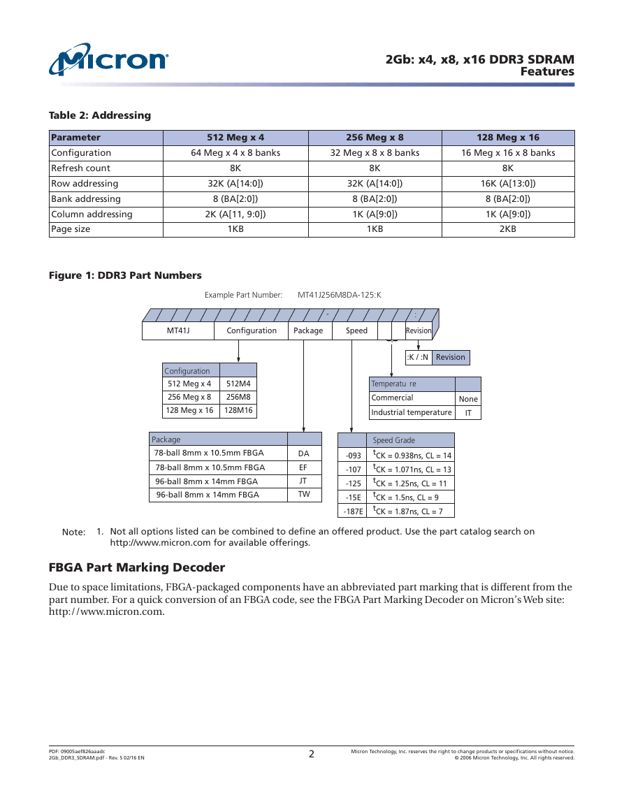
Table 2: Addressing
Parameter
Configuration
Refresh count
Row addressing
Bank addressing
Column addressing
Page size
512 Meg x 4
256 Meg x 8
128 Meg x 16
64 Meg x 4 x 8 banks
32 Meg x 8 x 8 banks
16 Meg x 16 x 8 banks
8K
32K (A[14:0])
8 (BA[2:0])
2K (A[11, 9:0])
1KB
8K
32K (A[14:0])
8 (BA[2:0])
1K (A[9:0])
1KB
8K
16K (A[13:0])
8 (BA[2:0])
1K (A[9:0])
2KB
Figure 1: DDR3 Part Numbers
Example Part Number: MT41J256M8DA-125:K
MT41J
Configuration
Package
Speed
Revision
-
:
Configuration
512 Meg x 4
256 Meg x 8
128 Meg x 16
512M4
256M8
128M16
{
:K / :N
Revision
Temperatu re
Commercial
Industrial temperature
None
IT
Package
78-ball 8mm x 10.5mm FBGA
78-ball 8mm x 10.5mm FBGA
96-ball 8mm x 14mm FBGA
96-ball 8mm x 14mm FBGA
DA
EF
JT
TW
-093
-107
-125
-15E
-187E
Speed Grade
tCK = 0.938ns, CL = 14
tCK = 1.071ns, CL = 13
tCK = 1.25ns, CL = 11
tCK = 1.5ns, CL = 9
tCK = 1.87ns, CL = 7
Note:
1. Not all options listed can be combined to define an offered product. Use the part catalog search on
http://www.micron.com for available offerings.
FBGA Part Marking Decoder
Due to space limitations, FBGA-packaged components have an abbreviated part marking that is different from the
part number. For a quick conversion of an FBGA code, see the FBGA Part Marking Decoder on Micron’s Web site:
http://www.micron.com.
PDF: 09005aef826aaadc
2Gb_DDR3_SDRAM.pdf - Rev. S 02/16 EN
2
Micron Technology, Inc. reserves the right to change products or specifications without notice.
© 2006 Micron Technology, Inc. All rights reserved.
�
2Gb: x4, x8, x16 DDR3 SDRAM
Features
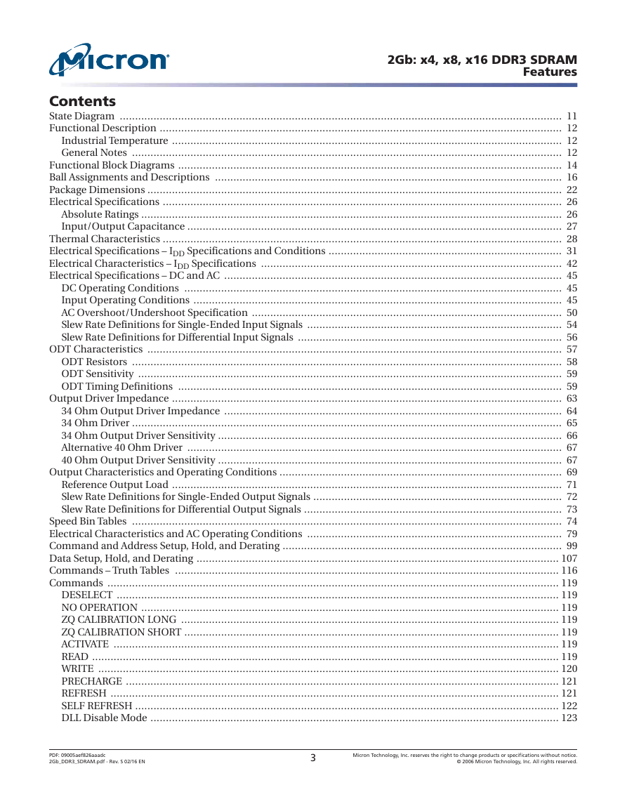
Contents
State Diagram ................................................................................................................................................ 11
Functional Description ................................................................................................................................... 12
Industrial Temperature ............................................................................................................................... 12
General Notes ............................................................................................................................................ 12
Functional Block Diagrams ............................................................................................................................. 14
Ball Assignments and Descriptions ................................................................................................................. 16
Package Dimensions ....................................................................................................................................... 22
Electrical Specifications .................................................................................................................................. 26
Absolute Ratings ......................................................................................................................................... 26
Input/Output Capacitance .......................................................................................................................... 27
Thermal Characteristics .................................................................................................................................. 28
Electrical Specifications – IDD Specifications and Conditions ............................................................................ 31
Electrical Characteristics – IDD Specifications .................................................................................................. 42
Electrical Specifications – DC and AC .............................................................................................................. 45
DC Operating Conditions ........................................................................................................................... 45
Input Operating Conditions ........................................................................................................................ 45
AC Overshoot/Undershoot Specification ..................................................................................................... 50
Slew Rate Definitions for Single-Ended Input Signals ................................................................................... 54
Slew Rate Definitions for Differential Input Signals ...................................................................................... 56
ODT Characteristics ....................................................................................................................................... 57
ODT Resistors ............................................................................................................................................ 58
ODT Sensitivity .......................................................................................................................................... 59
ODT Timing Definitions ............................................................................................................................. 59
Output Driver Impedance ............................................................................................................................... 63
34 Ohm Output Driver Impedance .............................................................................................................. 64
34 Ohm Driver ............................................................................................................................................ 65
34 Ohm Output Driver Sensitivity ................................................................................................................ 66
Alternative 40 Ohm Driver .......................................................................................................................... 67
40 Ohm Output Driver Sensitivity ................................................................................................................ 67
Output Characteristics and Operating Conditions ............................................................................................ 69
Reference Output Load ............................................................................................................................... 71
Slew Rate Definitions for Single-Ended Output Signals ................................................................................. 72
Slew Rate Definitions for Differential Output Signals .................................................................................... 73
Speed Bin Tables ............................................................................................................................................ 74
Electrical Characteristics and AC Operating Conditions ................................................................................... 79
Command and Address Setup, Hold, and Derating ........................................................................................... 99
Data Setup, Hold, and Derating ...................................................................................................................... 107
Commands – Truth Tables ............................................................................................................................. 116
Commands ................................................................................................................................................... 119
DESELECT ................................................................................................................................................ 119
NO OPERATION ........................................................................................................................................ 119
ZQ CALIBRATION LONG ........................................................................................................................... 119
ZQ CALIBRATION SHORT .......................................................................................................................... 119
ACTIVATE ................................................................................................................................................. 119
READ ........................................................................................................................................................ 119
WRITE ...................................................................................................................................................... 120
PRECHARGE ............................................................................................................................................. 121
REFRESH .................................................................................................................................................. 121
SELF REFRESH .......................................................................................................................................... 122
DLL Disable Mode ..................................................................................................................................... 123
PDF: 09005aef826aaadc
2Gb_DDR3_SDRAM.pdf - Rev. S 02/16 EN
3
Micron Technology, Inc. reserves the right to change products or specifications without notice.
© 2006 Micron Technology, Inc. All rights reserved.
�
2Gb: x4, x8, x16 DDR3 SDRAM
Features
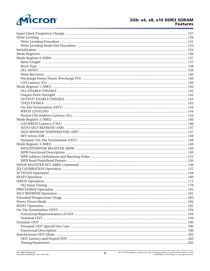
Input Clock Frequency Change ...................................................................................................................... 127
Write Leveling ............................................................................................................................................... 129
Write Leveling Procedure ........................................................................................................................... 131
Write Leveling Mode Exit Procedure ........................................................................................................... 133
Initialization ................................................................................................................................................. 134
Mode Registers .............................................................................................................................................. 136
Mode Register 0 (MR0) ................................................................................................................................... 137
Burst Length ............................................................................................................................................. 137
Burst Type ................................................................................................................................................. 138
DLL RESET ................................................................................................................................................ 139
Write Recovery .......................................................................................................................................... 140
Precharge Power-Down (Precharge PD) ...................................................................................................... 140
CAS Latency (CL) ....................................................................................................................................... 140
Mode Register 1 (MR1) ................................................................................................................................... 142
DLL ENABLE/DISABLE .............................................................................................................................. 142
Output Drive Strength ............................................................................................................................... 143
OUTPUT ENABLE/DISABLE ...................................................................................................................... 143
TDQS ENABLE .......................................................................................................................................... 143
On-Die Termination (ODT) ........................................................................................................................ 144
WRITE LEVELING ..................................................................................................................................... 144
Posted CAS Additive Latency (AL) ............................................................................................................... 144
Mode Register 2 (MR2) ................................................................................................................................... 146
CAS WRITE Latency (CWL) ........................................................................................................................ 146
AUTO SELF REFRESH (ASR) ....................................................................................................................... 147
SELF REFRESH TEMPERATURE (SRT) ........................................................................................................ 147
SRT versus ASR .......................................................................................................................................... 148
Dynamic On-Die Termination (ODT) ......................................................................................................... 148
Mode Register 3 (MR3) ................................................................................................................................... 149
MULTIPURPOSE REGISTER (MPR) ............................................................................................................ 149
MPR Functional Description ...................................................................................................................... 150
MPR Address Definitions and Bursting Order .............................................................................................. 151
MPR Read Predefined Pattern .................................................................................................................... 156
MODE REGISTER SET (MRS) Command ........................................................................................................ 156
ZQ CALIBRATION Operation ......................................................................................................................... 157
ACTIVATE Operation ..................................................................................................................................... 158
READ Operation ............................................................................................................................................ 160
WRITE Operation .......................................................................................................................................... 171
DQ Input Timing ....................................................................................................................................... 179
PRECHARGE Operation ................................................................................................................................. 181
SELF REFRESH Operation .............................................................................................................................. 181
Extended Temperature Usage ........................................................................................................................ 183
Power-Down Mode ........................................................................................................................................ 184
RESET Operation ........................................................................................................................................... 192
On-Die Termination (ODT) ............................................................................................................................ 194
Functional Representation of ODT ............................................................................................................. 194
Nominal ODT ............................................................................................................................................ 194
Dynamic ODT ............................................................................................................................................... 196
Dynamic ODT Special Use Case ................................................................................................................. 196
Functional Description .............................................................................................................................. 196
Synchronous ODT Mode ................................................................................................................................ 202
ODT Latency and Posted ODT .................................................................................................................... 202
Timing Parameters .................................................................................................................................... 202
PDF: 09005aef826aaadc
2Gb_DDR3_SDRAM.pdf - Rev. S 02/16 EN
4
Micron Technology, Inc. reserves the right to change products or specifications without notice.
© 2006 Micron Technology, Inc. All rights reserved.
�
2Gb: x4, x8, x16 DDR3 SDRAM
Features
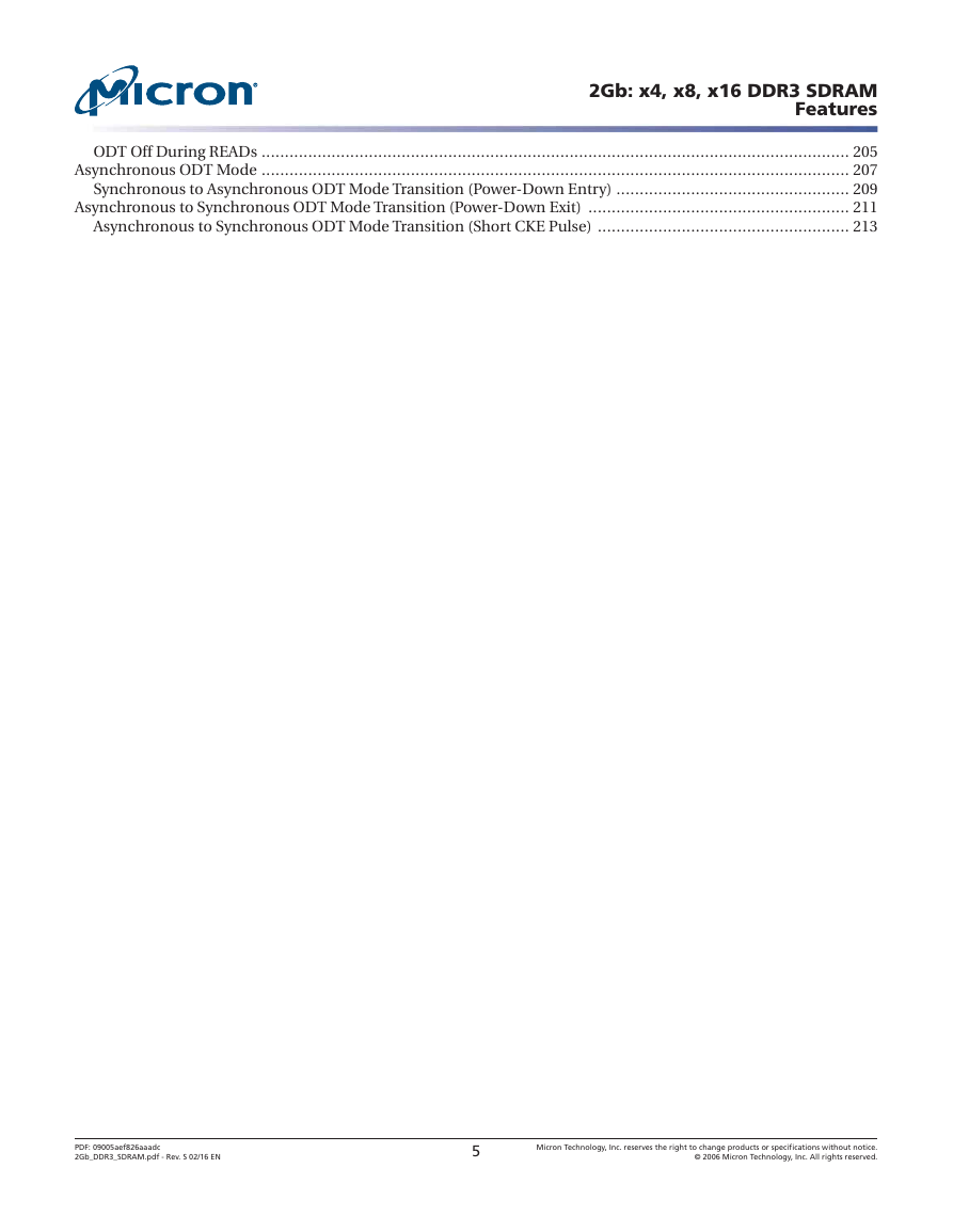
ODT Off During READs .............................................................................................................................. 205
Asynchronous ODT Mode .............................................................................................................................. 207
Synchronous to Asynchronous ODT Mode Transition (Power-Down Entry) .................................................. 209
Asynchronous to Synchronous ODT Mode Transition (Power-Down Exit) ........................................................ 211
Asynchronous to Synchronous ODT Mode Transition (Short CKE Pulse) ...................................................... 213
PDF: 09005aef826aaadc
2Gb_DDR3_SDRAM.pdf - Rev. S 02/16 EN
5
Micron Technology, Inc. reserves the right to change products or specifications without notice.
© 2006 Micron Technology, Inc. All rights reserved.
�
2Gb: x4, x8, x16 DDR3 SDRAM
Features
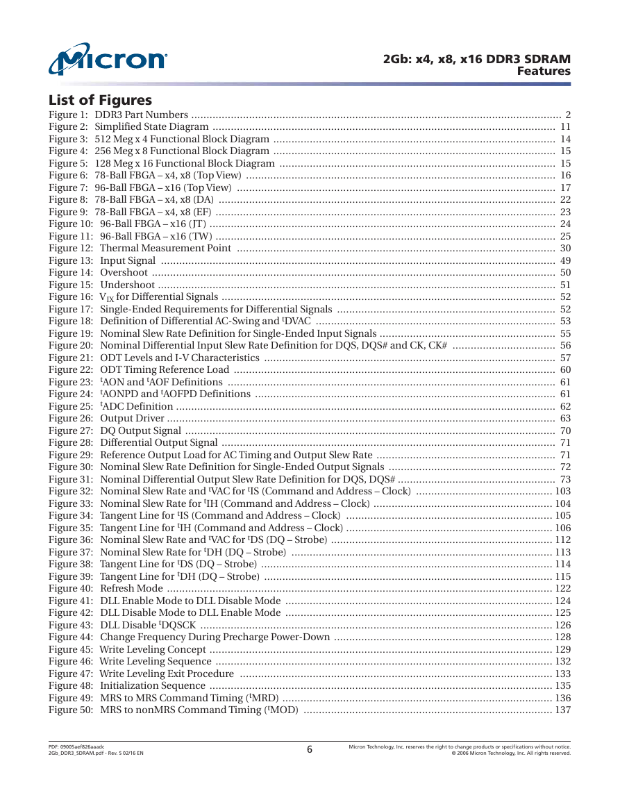
List of Figures
Figure 1: DDR3 Part Numbers .......................................................................................................................... 2
Figure 2: Simplified State Diagram ................................................................................................................. 11
Figure 3: 512 Meg x 4 Functional Block Diagram ............................................................................................. 14
Figure 4: 256 Meg x 8 Functional Block Diagram ............................................................................................. 15
Figure 5: 128 Meg x 16 Functional Block Diagram ........................................................................................... 15
Figure 6: 78-Ball FBGA – x4, x8 (Top View) ...................................................................................................... 16
Figure 7: 96-Ball FBGA – x16 (Top View) ......................................................................................................... 17
Figure 8: 78-Ball FBGA – x4, x8 (DA) ............................................................................................................... 22
Figure 9: 78-Ball FBGA – x4, x8 (EF) ................................................................................................................ 23
Figure 10: 96-Ball FBGA – x16 (JT) .................................................................................................................. 24
Figure 11: 96-Ball FBGA – x16 (TW) ................................................................................................................ 25
Figure 12: Thermal Measurement Point ......................................................................................................... 30
Figure 13: Input Signal .................................................................................................................................. 49
Figure 14: Overshoot ..................................................................................................................................... 50
Figure 15: Undershoot ................................................................................................................................... 51
Figure 16: VIX for Differential Signals .............................................................................................................. 52
Figure 17: Single-Ended Requirements for Differential Signals ........................................................................ 52
Figure 18: Definition of Differential AC-Swing and tDVAC ............................................................................... 53
Figure 19: Nominal Slew Rate Definition for Single-Ended Input Signals .......................................................... 55
Figure 20: Nominal Differential Input Slew Rate Definition for DQS, DQS# and CK, CK# .................................. 56
Figure 21: ODT Levels and I-V Characteristics ................................................................................................ 57
Figure 22: ODT Timing Reference Load .......................................................................................................... 60
Figure 23: tAON and tAOF Definitions ............................................................................................................ 61
Figure 24: tAONPD and tAOFPD Definitions ................................................................................................... 61
Figure 25: tADC Definition ............................................................................................................................. 62
Figure 26: Output Driver ................................................................................................................................ 63
Figure 27: DQ Output Signal .......................................................................................................................... 70
Figure 28: Differential Output Signal .............................................................................................................. 71
Figure 29: Reference Output Load for AC Timing and Output Slew Rate ........................................................... 71
Figure 30: Nominal Slew Rate Definition for Single-Ended Output Signals ....................................................... 72
Figure 31: Nominal Differential Output Slew Rate Definition for DQS, DQS# .................................................... 73
Figure 32: Nominal Slew Rate and tVAC for tIS (Command and Address – Clock) ............................................. 103
Figure 33: Nominal Slew Rate for tIH (Command and Address – Clock) ........................................................... 104
Figure 34: Tangent Line for tIS (Command and Address – Clock) .................................................................... 105
Figure 35: Tangent Line for tIH (Command and Address – Clock) .................................................................... 106
Figure 36: Nominal Slew Rate and tVAC for tDS (DQ – Strobe) ......................................................................... 112
Figure 37: Nominal Slew Rate for tDH (DQ – Strobe) ...................................................................................... 113
Figure 38: Tangent Line for tDS (DQ – Strobe) ................................................................................................ 114
Figure 39: Tangent Line for tDH (DQ – Strobe) ............................................................................................... 115
Figure 40: Refresh Mode ............................................................................................................................... 122
Figure 41: DLL Enable Mode to DLL Disable Mode ........................................................................................ 124
Figure 42: DLL Disable Mode to DLL Enable Mode ........................................................................................ 125
Figure 43: DLL Disable tDQSCK .................................................................................................................... 126
Figure 44: Change Frequency During Precharge Power-Down ........................................................................ 128
Figure 45: Write Leveling Concept ................................................................................................................. 129
Figure 46: Write Leveling Sequence ............................................................................................................... 132
Figure 47: Write Leveling Exit Procedure ....................................................................................................... 133
Figure 48: Initialization Sequence ................................................................................................................. 135
Figure 49: MRS to MRS Command Timing (tMRD) ......................................................................................... 136
Figure 50: MRS to nonMRS Command Timing (tMOD) .................................................................................. 137
PDF: 09005aef826aaadc
2Gb_DDR3_SDRAM.pdf - Rev. S 02/16 EN
6
Micron Technology, Inc. reserves the right to change products or specifications without notice.
© 2006 Micron Technology, Inc. All rights reserved.
�
2Gb: x4, x8, x16 DDR3 SDRAM
Features
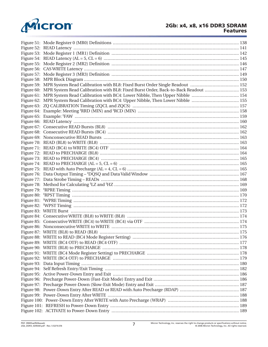
Figure 51: Mode Register 0 (MR0) Definitions ................................................................................................ 138
Figure 52: READ Latency .............................................................................................................................. 141
Figure 53: Mode Register 1 (MR1) Definition ................................................................................................. 142
Figure 54: READ Latency (AL = 5, CL = 6) ....................................................................................................... 145
Figure 55: Mode Register 2 (MR2) Definition ................................................................................................. 146
Figure 56: CAS WRITE Latency ...................................................................................................................... 147
Figure 57: Mode Register 3 (MR3) Definition ................................................................................................. 149
Figure 58: MPR Block Diagram ...................................................................................................................... 150
Figure 59: MPR System Read Calibration with BL8: Fixed Burst Order Single Readout ..................................... 152
Figure 60: MPR System Read Calibration with BL8: Fixed Burst Order, Back-to-Back Readout .......................... 153
Figure 61: MPR System Read Calibration with BC4: Lower Nibble, Then Upper Nibble .................................... 154
Figure 62: MPR System Read Calibration with BC4: Upper Nibble, Then Lower Nibble .................................... 155
Figure 63: ZQ CALIBRATION Timing (ZQCL and ZQCS) ................................................................................. 157
Figure 64: Example: Meeting tRRD (MIN) and tRCD (MIN) ............................................................................. 158
Figure 65: Example: tFAW ............................................................................................................................. 159
Figure 66: READ Latency .............................................................................................................................. 160
Figure 67: Consecutive READ Bursts (BL8) .................................................................................................... 162
Figure 68: Consecutive READ Bursts (BC4) .................................................................................................... 162
Figure 69: Nonconsecutive READ Bursts ....................................................................................................... 163
Figure 70: READ (BL8) to WRITE (BL8) .......................................................................................................... 163
Figure 71: READ (BC4) to WRITE (BC4) OTF .................................................................................................. 164
Figure 72: READ to PRECHARGE (BL8) .......................................................................................................... 164
Figure 73: READ to PRECHARGE (BC4) ......................................................................................................... 165
Figure 74: READ to PRECHARGE (AL = 5, CL = 6) ........................................................................................... 165
Figure 75: READ with Auto Precharge (AL = 4, CL = 6) ..................................................................................... 165
Figure 76: Data Output Timing – tDQSQ and Data Valid Window .................................................................... 167
Figure 77: Data Strobe Timing – READs ......................................................................................................... 168
Figure 78: Method for Calculating tLZ and tHZ ............................................................................................... 169
Figure 79: tRPRE Timing ............................................................................................................................... 169
Figure 80: tRPST Timing ............................................................................................................................... 170
Figure 81: tWPRE Timing .............................................................................................................................. 172
Figure 82: tWPST Timing .............................................................................................................................. 172
Figure 83: WRITE Burst ................................................................................................................................ 173
Figure 84: Consecutive WRITE (BL8) to WRITE (BL8) ..................................................................................... 174
Figure 85: Consecutive WRITE (BC4) to WRITE (BC4) via OTF ........................................................................ 174
Figure 86: Nonconsecutive WRITE to WRITE ................................................................................................. 175
Figure 87: WRITE (BL8) to READ (BL8) .......................................................................................................... 175
Figure 88: WRITE to READ (BC4 Mode Register Setting) ................................................................................. 176
Figure 89: WRITE (BC4 OTF) to READ (BC4 OTF) ........................................................................................... 177
Figure 90: WRITE (BL8) to PRECHARGE ........................................................................................................ 178
Figure 91: WRITE (BC4 Mode Register Setting) to PRECHARGE ...................................................................... 178
Figure 92: WRITE (BC4 OTF) to PRECHARGE ................................................................................................ 179
Figure 93: Data Input Timing ........................................................................................................................ 180
Figure 94: Self Refresh Entry/Exit Timing ...................................................................................................... 182
Figure 95: Active Power-Down Entry and Exit ................................................................................................ 186
Figure 96: Precharge Power-Down (Fast-Exit Mode) Entry and Exit ................................................................. 186
Figure 97: Precharge Power-Down (Slow-Exit Mode) Entry and Exit ................................................................ 187
Figure 98: Power-Down Entry After READ or READ with Auto Precharge (RDAP) ............................................. 187
Figure 99: Power-Down Entry After WRITE .................................................................................................... 188
Figure 100: Power-Down Entry After WRITE with Auto Precharge (WRAP) ...................................................... 188
Figure 101: REFRESH to Power-Down Entry .................................................................................................. 189
Figure 102: ACTIVATE to Power-Down Entry ................................................................................................. 189
PDF: 09005aef826aaadc
2Gb_DDR3_SDRAM.pdf - Rev. S 02/16 EN
7
Micron Technology, Inc. reserves the right to change products or specifications without notice.
© 2006 Micron Technology, Inc. All rights reserved.
�
2Gb: x4, x8, x16 DDR3 SDRAM
Features
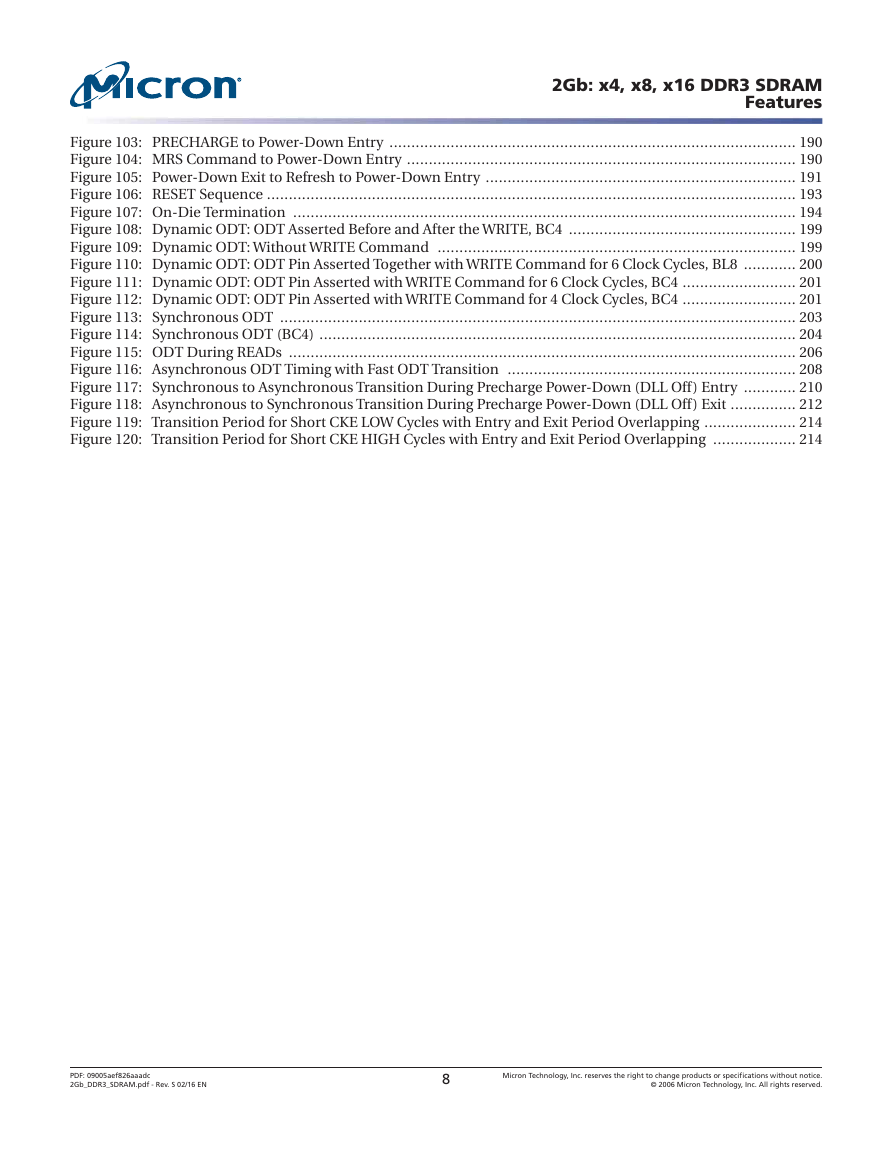
Figure 103: PRECHARGE to Power-Down Entry ............................................................................................. 190
Figure 104: MRS Command to Power-Down Entry ......................................................................................... 190
Figure 105: Power-Down Exit to Refresh to Power-Down Entry ....................................................................... 191
Figure 106: RESET Sequence ......................................................................................................................... 193
Figure 107: On-Die Termination ................................................................................................................... 194
Figure 108: Dynamic ODT: ODT Asserted Before and After the WRITE, BC4 .................................................... 199
Figure 109: Dynamic ODT: Without WRITE Command .................................................................................. 199
Figure 110: Dynamic ODT: ODT Pin Asserted Together with WRITE Command for 6 Clock Cycles, BL8 ............ 200
Figure 111: Dynamic ODT: ODT Pin Asserted with WRITE Command for 6 Clock Cycles, BC4 .......................... 201
Figure 112: Dynamic ODT: ODT Pin Asserted with WRITE Command for 4 Clock Cycles, BC4 .......................... 201
Figure 113: Synchronous ODT ...................................................................................................................... 203
Figure 114: Synchronous ODT (BC4) ............................................................................................................. 204
Figure 115: ODT During READs .................................................................................................................... 206
Figure 116: Asynchronous ODT Timing with Fast ODT Transition .................................................................. 208
Figure 117: Synchronous to Asynchronous Transition During Precharge Power-Down (DLL Off) Entry ............ 210
Figure 118: Asynchronous to Synchronous Transition During Precharge Power-Down (DLL Off) Exit ............... 212
Figure 119: Transition Period for Short CKE LOW Cycles with Entry and Exit Period Overlapping ..................... 214
Figure 120: Transition Period for Short CKE HIGH Cycles with Entry and Exit Period Overlapping ................... 214
PDF: 09005aef826aaadc
2Gb_DDR3_SDRAM.pdf - Rev. S 02/16 EN
8
Micron Technology, Inc. reserves the right to change products or specifications without notice.
© 2006 Micron Technology, Inc. All rights reserved.
�


 2023年江西萍乡中考道德与法治真题及答案.doc
 2012年重庆南川中考生物真题及答案.doc
 2013年江西师范大学地理学综合及文艺理论基础考研真题.doc
 2020年四川甘孜小升初语文真题及答案I卷.doc
 2020年注册岩土工程师专业基础考试真题及答案.doc
 2023-2024学年福建省厦门市九年级上学期数学月考试题及答案.doc
 2021-2022学年辽宁省沈阳市大东区九年级上学期语文期末试题及答案.doc
 2022-2023学年北京东城区初三第一学期物理期末试卷及答案.doc
 2018上半年江西教师资格初中地理学科知识与教学能力真题及答案.doc
 2012年河北国家公务员申论考试真题及答案-省级.doc
 2020-2021学年江苏省扬州市江都区邵樊片九年级上学期数学第一次质量检测试题及答案.doc
 2022下半年黑龙江教师资格证中学综合素质真题及答案.doc