《有限元数值模拟与虚拟工程》第二次作业
原题:
备注:本人学号为******1596
解:
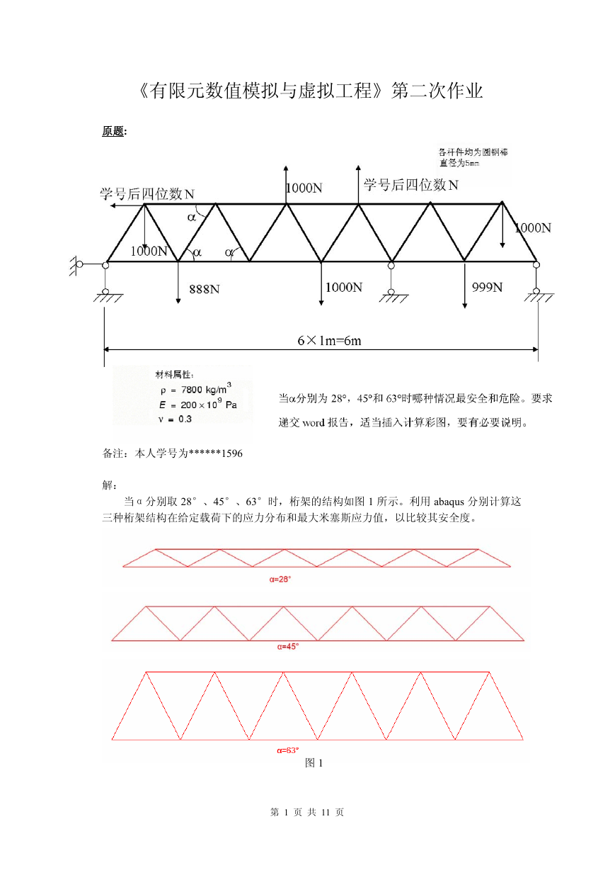
当α分别取 28°、45°、63°时,桁架的结构如图 1 所示。利用 abaqus 分别计算这
三种桁架结构在给定载荷下的应力分布和最大米塞斯应力值,以比较其安全度。
图 1
第 1 页 共 11 页
�
下面以α=28°的情况为例,简述 abaqus 的分析步骤和计算结果。
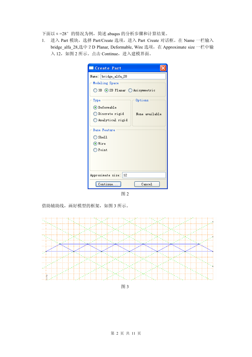
1. 进入 Part 模块,选择 Part/Create 选项,进入 Part Create 对话框。在 Name 一栏输入
bridge_alfa_28,选中2D Planar, Deformable, Wire 选项,在 Approximate size 一栏中输
入 12,如图 2 所示。点击 Continue,进入建模界面。
借助辅助线,画好模型的框架,如图 3 所示。
图 2
图 3
第 2 页 共 11 页
�
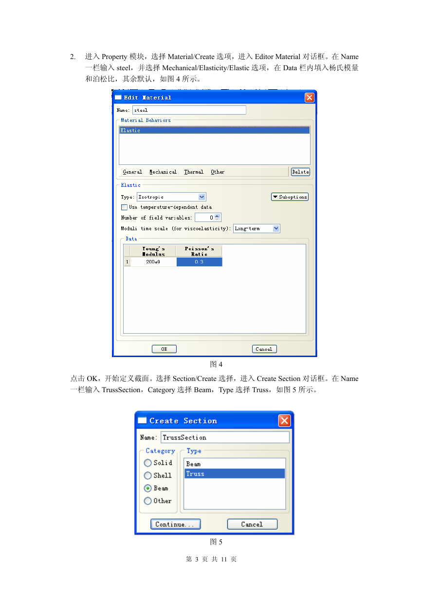
2. 进入 Property 模块,选择 Material/Create 选项,进入 Editor Material 对话框。在 Name
一栏输入 steel,并选择 Mechanical/Elasticity/Elastic 选项,在 Data 栏内填入杨氏模量
和泊松比,其余默认,如图 4 所示。
图 4
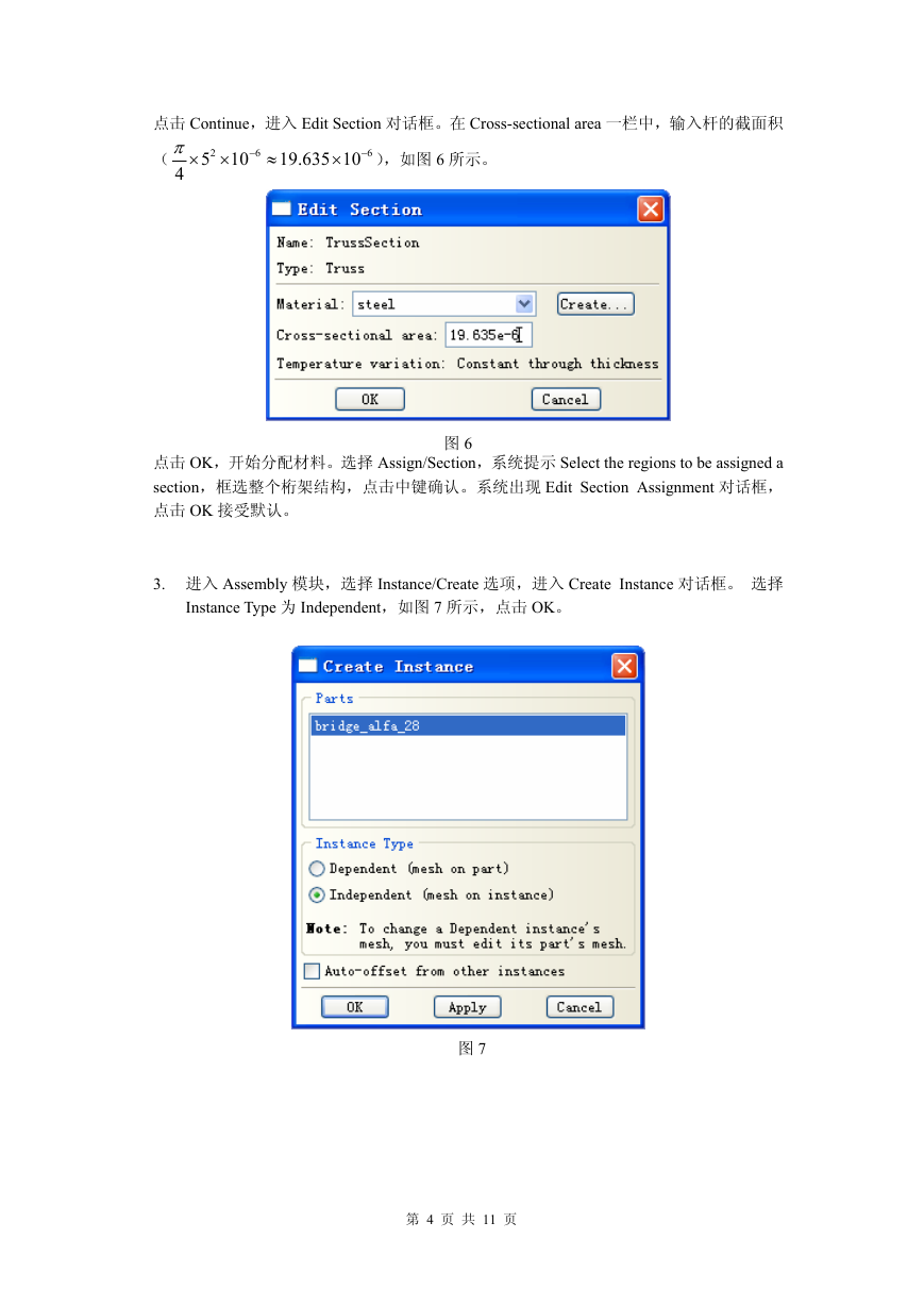
点击 OK,开始定义截面。选择 Section/Create 选择,进入 Create Section 对话框。在 Name
一栏输入 TrussSection,Category 选择 Beam,Type 选择 Truss,如图 5 所示。
图 5
第 3 页 共 11 页
�
点击 Continue,进入 Edit Section 对话框。在 Cross-sectional area 一栏中,输入杆的截面积
(
π
×
4
2
5
×
10
6
−
≈
19.635 10
× − ),如图 6 所示。
6
图 6
点击 OK,开始分配材料。选择 Assign/Section,系统提示 Select the regions to be assigned a
section,框选整个桁架结构,点击中键确认。系统出现 Edit Section Assignment 对话框,
点击 OK 接受默认。
3. 进入 Assembly 模块,选择 Instance/Create 选项,进入 Create Instance 对话框。 选择
Instance Type 为 Independent,如图 7 所示,点击 OK。
图 7
第 4 页 共 11 页
�
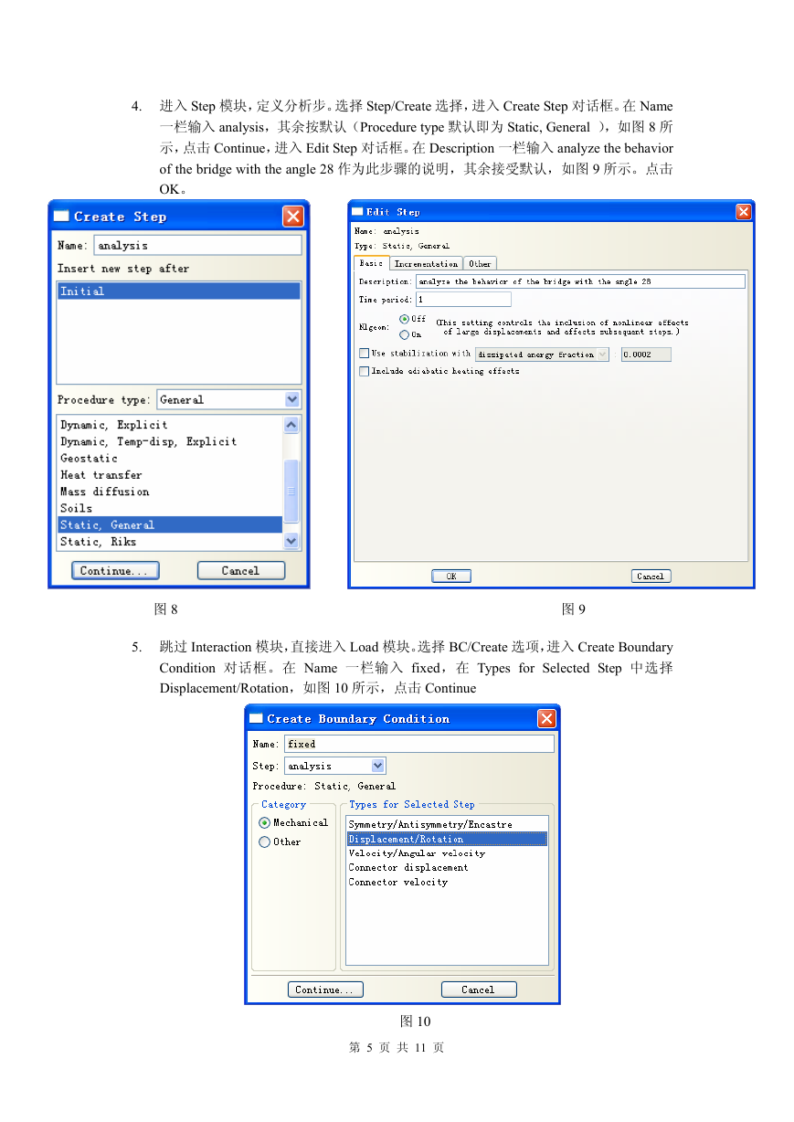
4. 进入 Step 模块,定义分析步。选择 Step/Create 选择,进入 Create Step 对话框。在 Name
一栏输入 analysis,其余按默认(Procedure type 默认即为 Static, General ),如图 8 所
示,点击 Continue,进入 Edit Step 对话框。在 Description 一栏输入 analyze the behavior
of the bridge with the angle 28 作为此步骤的说明,其余接受默认,如图 9 所示。点击
OK。
图 8
5. 跳过 Interaction 模块,直接进入 Load 模块。选择 BC/Create 选项,进入 Create Boundary
Condition 对话框。在 Name 一栏输入 fixed,在 Types for Selected Step 中选择
Displacement/Rotation,如图 10 所示,点击 Continue
图 9
图 10
第 5 页 共 11 页
�
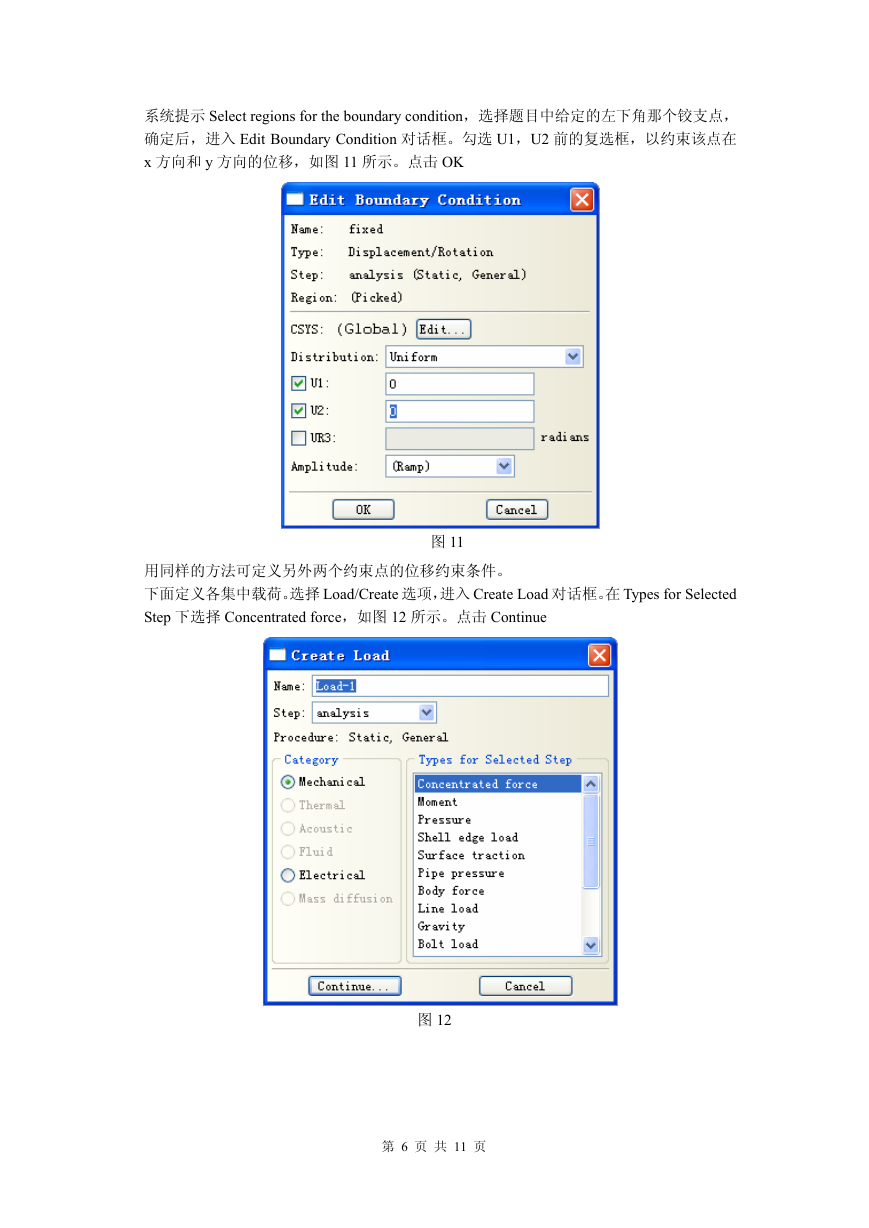
系统提示 Select regions for the boundary condition,选择题目中给定的左下角那个铰支点,
确定后,进入 Edit Boundary Condition 对话框。勾选 U1,U2 前的复选框,以约束该点在
x 方向和 y 方向的位移,如图 11 所示。点击 OK
图 11
用同样的方法可定义另外两个约束点的位移约束条件。
下面定义各集中载荷。选择 Load/Create 选项,进入 Create Load 对话框。在 Types for Selected
Step 下选择 Concentrated force,如图 12 所示。点击 Continue
图 12
第 6 页 共 11 页
�
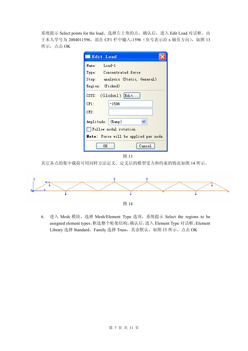
系统提示 Select points for the load。选择左上角的点,确认后,进入 Edit Load 对话框。由
于本人学号为 2004011596,故在 CF1 栏中输入-1596(负号表示沿 x 轴负方向),如图 13
所示,点击 OK
其它各点的集中载荷可用同样方法定义。定义后的模型受力和约束的情况如图 14 所示。
图 13
图 14
6. 进入 Mesh 模块,选择 Mesh/Element Type 选项,系统提示 Select the regions to be
assigned element types。框选整个桁架结构,确认后,进入 Element Type 对话框。Element
Library 选择 Standard,Family 选择 Truss,其余默认,如图 15 所示。点击 OK
第 7 页 共 11 页
�
图 15
选择 Seed/Edge By Number,系统提示 Select the regions to be assigned local seeds,框选整
个桁架结构,确认后,系统提示输入每条边上的单元数,在提示框内输入 1,即每条边上
一个单元,如图 16 所示。
图 16
确认后,选择 Mesh/Instance 选项,系统提示 OK to mesh the part instance?,选择 yes,网
格生成完毕。
7. 进入 Job 模块,选择 Job/Create 选项,进入 Create Job 对话框。在 Name 一栏输入
analysis_bridge_alfa28,如图 17 所示。点击 Continue,进入 Edit Job 对话框。在Description
一栏中输入 analyze the behavior of the bridge with the angle 28 以对任务进行说明,其
余接受默认,如图 18 所示。点击 OK
第 8 页 共 11 页
�


 2023年江西萍乡中考道德与法治真题及答案.doc
 2012年重庆南川中考生物真题及答案.doc
 2013年江西师范大学地理学综合及文艺理论基础考研真题.doc
 2020年四川甘孜小升初语文真题及答案I卷.doc
 2020年注册岩土工程师专业基础考试真题及答案.doc
 2023-2024学年福建省厦门市九年级上学期数学月考试题及答案.doc
 2021-2022学年辽宁省沈阳市大东区九年级上学期语文期末试题及答案.doc
 2022-2023学年北京东城区初三第一学期物理期末试卷及答案.doc
 2018上半年江西教师资格初中地理学科知识与教学能力真题及答案.doc
 2012年河北国家公务员申论考试真题及答案-省级.doc
 2020-2021学年江苏省扬州市江都区邵樊片九年级上学期数学第一次质量检测试题及答案.doc
 2022下半年黑龙江教师资格证中学综合素质真题及答案.doc