logo资料库

cxl_spec_v1p1.pdf

第1页 / 共250页
第2页 / 共250页
第3页 / 共250页
第4页 / 共250页
第5页 / 共250页
第6页 / 共250页
第7页 / 共250页
第8页 / 共250页
资料共250页,剩余部分请下载后查看
Compute Express Link
Contents
Figures
Tables
Revision History
1.0 Introduction
1.1 Audience
1.2 Terminology / Acronyms
1.3 Reference Documents
1.4 Motivation and Overview
1.4.1 Compute Express Link
1.4.2 Flex Bus
1.5 Flex Bus Link Features
1.6 Flex Bus Layering Overview
1.7 Document Scope
2.0 Compute Express Link System Architecture
2.1 Type 1 CXL Device
2.2 Type 2 Device
2.2.1 Bias Based Coherency Model
2.2.1.1 Host Bias
2.2.1.2 Device Bias
2.2.1.3 Mode Management
2.2.1.4 Software Assisted Bias Mode Management
2.2.1.5 HW Autonomous Bias Mode Management
2.3 Type 3
3.0 Compute Express Link Transaction Layer
3.1 CXL.io
3.1.1 PCIe Root Complex Integrated Endpoint
3.1.2 CXL Power Management VDM Format
3.1.2.1 Credit and PM Initialization
3.1.3 Optional PCIe Features Required for CXL
3.1.4 Error Propagation
3.1.5 Memory Type Indication on ATS
3.1.6 Deferrable Writes
3.2 CXL.cache
3.2.1 Overview
3.2.2 CXL.cache Channel Description
3.2.2.1 Channel Ordering
3.2.2.2 Channel Crediting
3.2.3 CXL.cache Wire Description
3.2.3.1 D2H Request
3.2.3.2 D2H Response
3.2.3.3 D2H Data
3.2.3.4 H2D Request
3.2.3.5 H2D Response
3.2.3.6 H2D Data
3.2.4 CXL.cache Transaction Description
3.2.4.1 Device to Host Requests
3.2.4.2 Device to Host Response
3.2.4.3 Host to Device Requests
3.2.4.4 Host to Device Response
3.2.5 Cacheability Details and Request Restrictions
3.2.5.1 GO-M Responses
3.2.5.2 Device/Host Snoop-GO-Data Assumptions
3.2.5.3 Device/Host Snoop/WritePull Assumptions
3.2.5.4 Snoop Responses and Data Transfer on CXL.cache Evicts
3.2.5.5 Multiple Snoops to the same address
3.2.5.6 Multiple Reads to the same cache line
3.2.5.7 Multiple Evicts to the same cache line
3.2.5.8 Multiple WriteRequests to the same cache line
3.2.5.9 Normal Global Observation (GO)
3.2.5.10 Relaxed Global Observation (FastGO)
3.2.5.11 Evict to Device-Attached Memory
3.2.5.12 Memory Type on CXL.cache
3.2.5.13 General Assumptions
3.3 CXL.mem
3.3.1 Introduction
3.3.2 M2S Request (Req)
3.3.3 M2S Request with Data (RwD)
3.3.4 S2M No Data Response (NDR)
3.3.5 S2M Data Response (DRS)
3.3.6 Forward Progress & Ordering Rules
3.4 Transaction Flows to Device-Attached Memory
3.4.1 Flows for Type 1 and Type 2 Devices
3.4.1.1 Notes and Assumptions
3.4.1.2 Requests from Host
3.4.1.3 Requests from Device in Host & Device Bias
3.5 Flows for Type 3 Devices
4.0 Compute Express Link Link Layers
4.1 CXL.io Link Layer
4.2 CXL.mem and CXL.cache Common Link Layer
4.2.1 Introduction
4.2.2 High-Level CXL.cache/CXL.mem Flit Overview
4.2.3 Slot Format Definition
4.2.3.1 RSVD Fields
4.2.3.2 H2D & M2S Formats
4.2.3.3 D2H & S2M Formats
4.2.4 Link Layer Registers
4.2.5 Flit Packing Rules
4.2.6 Link Layer Control Flit
4.2.7 Link Layer Initialization
4.2.8 CXL.cache/CXL.mem Link Layer Retry
4.2.8.1 LLR Variables
4.2.8.2 ACK Forcing
4.2.8.3 LLR Control Flits
4.2.8.4 RETRY Framing Sequences
4.2.8.5 LLR State Machines
4.2.8.6 Interaction with Physical Layer Reset or Reinitialization
4.2.8.7 CXL.cache/CXL.mem Flit CRC
4.2.9 CXL.cache-Side Poison and Viral
4.2.9.1 Viral
5.0 Compute Express Link ARB/MUX
5.1 Virtual LSM States
5.1.1 Rules for Virtual LSM State Transitions Across Link
5.1.1.1 General Rules
5.1.1.2 Entry to Active Exchange Protocol
5.1.1.3 Status Synchronization Protocol
5.1.1.4 State Request ALMP
5.1.1.5 State Status ALMP
5.1.1.6 Unexpected ALMPs
5.2 ARB/MUX Link Management Packets
5.2.1 ARB/MUX Bypass Feature
5.3 Arbitration and Data Multiplexing/Demultiplexing
6.0 Flex Bus Physical Layer
6.1 Overview
6.2 Flex Bus.CXL Framing and Packet Layout
6.2.1 Ordered Set Blocks and Data Blocks
6.2.2 Protocol ID[15:0]
6.2.3 x16 Packet Layout
6.2.4 x8 Packet Layout
6.2.5 x4 Packet Layout
6.2.6 x2 Packet Layout
6.2.7 x1 Packet Layout
6.2.8 Special Case: CXL.io -- When a TLP Ends on a Flit Boundary
6.2.9 Framing Errors
6.3 Link Training
6.3.1 PCIe vs Flex Bus.CXL mode selection
6.3.1.1 Hardware Autonomous Mode Negotiation
6.3.1.2 Flex Bus.CXL Negotiation with Maximum Supported Link Speed of 8GT/s or 16GT/s
6.3.1.3 Link Width Degradation and Speed Downgrade
6.4 Recovery.Idle and Config.Idle Transitions to L0
6.5 L1 Abort Scenario
6.6 Exit from Recovery
6.7 Retimers and Low Latency Mode
6.7.1 Control SKP Ordered Set Frequency and L1/Recovery Entry
7.0 Control and Status Registers
7.1 Configuration Space Registers
7.1.1 PCI Express Designated Vendor-Specific Extended Capability (DVSEC) for CXL Device
7.1.1.1 DVSEC Flex Bus Capability (Offset 0Ah)
7.1.1.2 DVSEC Flex Bus Control (Offset 0Ch)
7.1.1.3 DVSEC Flex Bus Status (Offset 0Eh)
7.1.1.4 DVSEC Flex Bus Control2 (Offset 10h)
7.1.1.5 DVSEC Flex Bus Status2 (Offset 12h)
7.1.1.6 DVSEC Flex Bus Lock (Offset 14h)
7.1.1.7 DVSEC Flex Bus Range registers
7.2 Memory Mapped Registers
7.2.1 Upstream and Downstream Port Registers
7.2.1.1 CXL Downstream Port RCRB
7.2.1.2 CXL Upstream Port RCRB
7.2.1.3 Upstream and Downstream Flex Bus Port DVSEC
7.2.2 CXL Upstream and Downstream Port Subsystem Component Registers
7.2.2.1 CXL.cache and CXL.mem Registers
7.2.2.2 CXL ARB/MUX Registers
7.3 CXL RCRB Base Register
8.0 Reset, Initialization, Configuration and Manageability
8.1 Compute Express Link Boot and Reset Overview
8.1.1 General
8.1.2 Comparing CXL and PCIe behavior
8.2 Compute Express Link Device Boot Flow
8.3 Compute Express Link Device Warm Reset Entry Flow
8.4 Compute Express Link Device Cold Reset Entry Flow
8.5 Compute Express Link Device Sleep State Entry Flow
8.6 Function Level Reset (FLR)
8.7 Hotplug
8.8 Software Enumeration
8.8.1 Software Model
8.8.2 PCIe Software View of the Hierarchy
8.8.2.1 BIOS View
8.8.2.2 OS View
8.8.3 BIOS Enumeration Flow
8.8.4 Software View of CXL.cache
8.9 Accelerators with Multiple Flex Bus Links
8.9.1 Single CPU Topology
8.9.2 Multiple CPU Topology
8.10 Software View of HDM
8.10.1 Accelerator HMAT Fragment Table Format
8.11 Manageability Model for CXL Devices Matches PCIe
9.0 Power Management
9.1 Statement of Requirements
9.2 Policy based Runtime Control - Idle Power - Protocol Flow
9.2.1 General
9.2.2 Package-Level Idle (C-state) Entry and Exit Coordination
9.2.3 PkgC Entry flows
9.2.4 PkgC Exit Flows
9.3 Compute Express Link Physical Layer Power Management States
9.4 Compute Express Link Power Management
9.4.1 Compute Express Link PM Entry Phase 1
9.4.2 Compute Express Link PM Entry Phase 2
9.4.3 Compute Express Link PM Entry Phase 3
9.4.4 Compute Express Link Exit from ASPM L1
9.5 CXL.io Link Power Management
9.5.1 CXL.io ASPM Phase L1 Entry
9.5.2 CXL.io ASPM Phase 2 Entry
9.5.3 CXL.io ASPM Phase 3 Entry
9.6 CXL.cache + CXL.mem Link Power Management
10.0 Security
11.0 Reliability, Availability and Serviceability
11.1 Supported RAS Features
11.2 CXL Error Handling
11.2.1 Protocol and Link Layer Error Reporting
11.2.1.1 CXL Downstream Port (DP) Detected Errors
11.2.2 CXL Device Error Handling
11.2.2.1 CXL.mem and CXL.cache Errors
11.2.2.2 CXL Device Error Handling Flows
11.3 CXL Link Down Handling
11.4 CXL Viral Handling
11.5 CXL Error Injection
12.0 Platform Architecture
12.1 Flex Bus connector definition
12.1.1 Connector Type
12.1.2 Pin Count
12.2 Topologies
12.3 Protocol Detection
12.4 AIC Form Factor
12.5 AIC Power Envelope
12.6 Flexbus Slot Auxiliary Power
13.0 Performance Considerations
14.0 CXL Compliance Testing
14.1 Applicable Devices Under Test (DUTs)
14.2 Starting Configuration/Topology (Common for All Tests)
14.3 CXL.cache and CXL.io Application Layer/Transaction Layer Testing
14.3.1 General Testing Overview
14.3.2 Algorithms
14.3.3 Algorithm 1a: Multiple Write Streaming
14.3.4 Algorithm 1b: Multiple Write Streaming with Bogus Writes
14.3.5 Algorithm 2: Producer Consumer Test
14.3.6 Test Descriptions
14.3.6.1 Application Layer/Transaction Layer Tests
14.4 ARB/MUX
14.4.1 Reset to Active Transition
14.4.2 ARB/MUX Multiplexing (Requires Protocol Analyzer)
14.4.3 Active to L1.x Transition (If Applicable)
14.4.4 L1.x State Resolution (If Applicable)
14.4.5 Active to L2 Transition
14.4.6 L1 to Active Transition (If Applicable)
14.4.7 Reset Entry
14.4.8 Entry into L0 Synchronization (Requires Protocol Analyzer)
14.4.9 ARB/MUX Tests Requiring Injection Capabilities
14.4.9.1 ARB/MUX Bypass (Requires Protocol Analyzer)
14.4.9.2 Repeated ALMP Request
14.4.9.3 PM State Request Rejection (Requires Protocol Analyzer)
14.4.9.4 Unexpected Status ALMP
14.4.9.5 ALMP Error
14.4.9.6 Recovery Re-entry
14.5 Physical Layer
14.5.1 Protocol ID Checks (Requires Protocol Analyzer)
14.5.2 NULL Flit (Requires Protocol Analyzer)
14.5.3 EDS Token (Requires Protocol Analyzer)
14.5.4 Correctable Framing Error
14.5.5 Uncorrectable Framing Error
14.5.6 Unexpected Protocol ID
14.5.7 Sync Header Bypass (Requires Protocol Analyzer) (If Applicable)
14.5.8 Link Speed Advertisement (Requires Protocol Analyzer)
14.5.9 Idle Transition to L0 (Requires Protocol Analyzer)
14.5.10 Drift Buffer (If Applicable)
14.5.11 SKP OS Scheduling/Alternation (Requires Protocol Analyzer) (If Applicable)
14.5.12 SKP OS Exiting the Data Stream (Requires Protocol Analyzer) (If Applicable)
14.5.13 Link Speed Degradation - CXL Mode
14.5.14 Link Speed Degradation Below 8GT/s
14.5.15 Tests Requiring Injection Capabilities
14.5.15.1 TLP Ends On Flit Boundary (Requires Protocol Analyzer)
14.5.15.2 Failed CXL Mode Link Up
14.6 Configuration Register Tests
14.6.1 Device Presence.
14.6.2 Flex Bus Device DVSEC Capability Header
14.6.3 DVSEC Capability Structure
14.6.4 DVSEC Control Structure
14.6.5 DVSEC Control Lock
14.7 Memory Device Tests
14.7.1 Flex Bus Range 1
14.7.2 Flex Bus Range 2
14.8 Memory Mapped Registers
14.8.1 RCRB MEMBAR0 location
14.9 Reset and Initialization Tests
14.9.1 Warm Reset Test
14.9.2 Cold Reset Test
14.9.3 Sleep State Test
14.9.4 Function Level Reset Test
14.9.5 Flex Bus Range Setup Time
14.9.6 FLR Memory
14.10 Reliability, Availability, and Serviceability
14.10.1 RAS Configuration
14.10.1.1 AER Support
14.10.1.2 CXL.io Poison Injection from Device to Host
14.10.1.3 CXL.cache Poison Injection
14.10.1.4 CXL.cache CRC Injection (Protocol Analyzer Required)
14.10.1.5 CXL.mem Poison Injection
14.10.1.6 CXL.mem CRC Injection (Protocol Analyzer Required)
14.10.1.7 Flow Control Injection
14.10.1.8 Unexpected Completion Injection
14.10.1.9 Completion Timeout
14.11 Device Capability and Test Configuration Control
14.11.1 CXL Device Test Capability Advertisement
14.11.2 Device Capabilities to Support the Test Algorithms
14.11.3 Debug Capabilities in Device
14.11.3.1 Error Logging
14.11.3.2 Event Monitors
Appendix A Taxonomy
A.1 Accelerator Usage Taxonomy
A.2 Bias Model Flow Example – From CPU
A.3 CPU Support for Bias Modes
14.11.4 Directory in Accelerator Attached Memory
A.4 Giant Cache Model
Compute Express Link Specification June 2019 Revision: 1.1 EVALUATION COPY
The copyright in this Specification is owned by CXL as a Contractual SIG. Use of this Specification and any related intellectual property (collectively, the “Specification”), is governed by the terms of the Promoter, Contributor or Adopter Agreement (collectively, “Agreement”) as available by request from admin@computeexpresslink.org. This specification may only be used by (a) a party to the Agreement, and in compliance with its terms, or (b) non-parties to the Agreement who have accepted an approved disclaimer of liability and acknowledgement of IP protections. Any use or implementation of this specification is expressly subject to the terms and conditions described in the CXL Promoter, Contributor, and/or Adopter Agreement, as appropriate for your status. The implementation or use of industry specifications made available by any other standards body, such as PCIe, if referenced in a CXL Final Specification (as such term is defined in those agreements) is not governed by CXL policies and procedures, and may be subject to patent, copyright, and other intellectual property right protection (collectively “IPR”). Licensing of such IPR in a referenced industry specification shall be governed by the policies and procedures of the organization promulgating such industry specification. This document is provided ‘as is’ with no warranties, express or implied, including any warranty of merchantability, fitness for a particular purpose, noninfringement of any third-party intellectual property rights, or any warranty otherwise arising out of any proposal, specification or sample. No license, express or implied, by estoppel or otherwise, to any intellectual property rights is granted herein. CXL is a trademark of the CXL Contractual SIG All other product names are trademarks, registered trademarks, or servicemarks of their respective owners. ©2019 CXL June 2019 Revision 1.1 Compute Express Link Specification 2 EVALUATION COPY
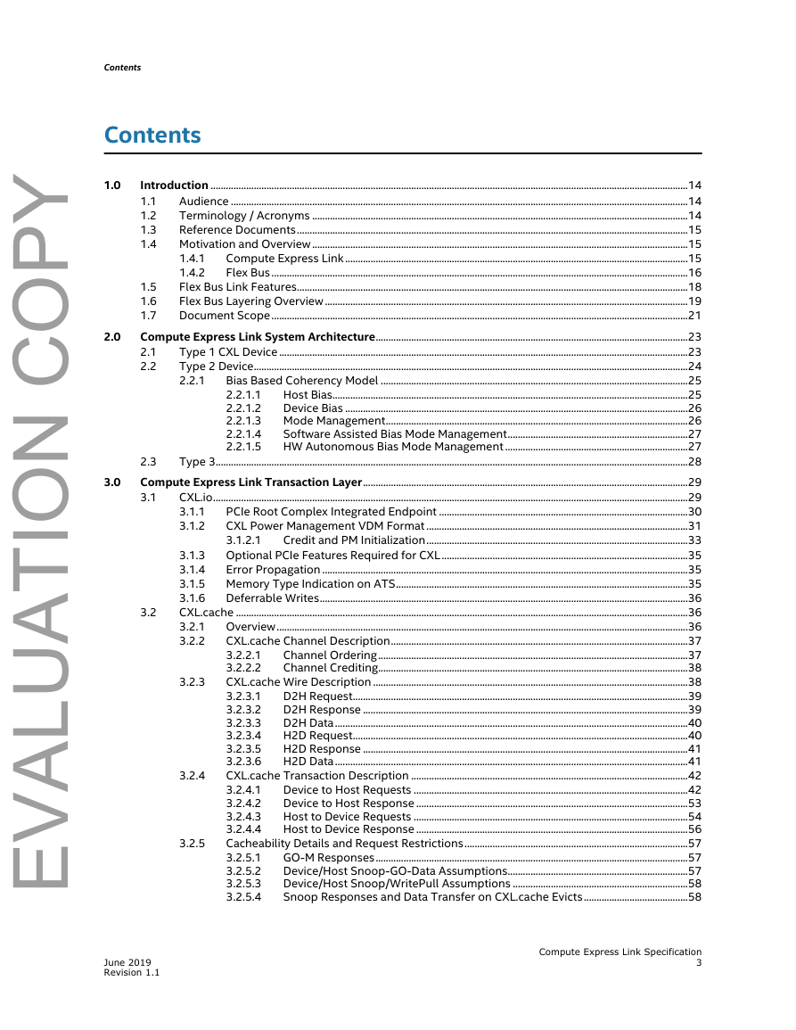
Contents Contents 1.0 2.0 3.0 Introduction ............................................................................................................................................................................................14 Audience ....................................................................................................................................................................................14 1.1 Terminology / Acronyms ....................................................................................................................................................14 1.2 1.3 Reference Documents..........................................................................................................................................................15 Motivation and Overview....................................................................................................................................................15 1.4 Compute Express Link.......................................................................................................................................15 1.4.1 1.4.2 Flex Bus ....................................................................................................................................................................16 Flex Bus Link Features..........................................................................................................................................................18 1.5 Flex Bus Layering Overview ...............................................................................................................................................19 1.6 1.7 Document Scope....................................................................................................................................................................21 Compute Express Link System Architecture...........................................................................................................................23 Type 1 CXL Device .................................................................................................................................................................23 2.1 2.2 Type 2 Device...........................................................................................................................................................................24 Bias Based Coherency Model .........................................................................................................................25 2.2.1 Host Bias............................................................................................................................................25 2.2.1.1 Device Bias .......................................................................................................................................26 2.2.1.2 Mode Management.......................................................................................................................26 2.2.1.3 2.2.1.4 Software Assisted Bias Mode Management.......................................................................27 HW Autonomous Bias Mode Management ........................................................................27 2.2.1.5 2.3 Type 3..........................................................................................................................................................................................28 Compute Express Link Transaction Layer................................................................................................................................29 3.1 CXL.io...........................................................................................................................................................................................29 PCIe Root Complex Integrated Endpoint ..................................................................................................30 3.1.1 CXL Power Management VDM Format .......................................................................................................31 3.1.2 3.1.2.1 Credit and PM Initialization.......................................................................................................33 Optional PCIe Features Required for CXL.................................................................................................35 3.1.3 Error Propagation ................................................................................................................................................35 3.1.4 Memory Type Indication on ATS...................................................................................................................35 3.1.5 3.1.6 Deferrable Writes.................................................................................................................................................36 CXL.cache ..................................................................................................................................................................................36 3.2.1 Overview..................................................................................................................................................................36 CXL.cache Channel Description.....................................................................................................................37 3.2.2 Channel Ordering..........................................................................................................................37 3.2.2.1 3.2.2.2 Channel Crediting..........................................................................................................................38 CXL.cache Wire Description ............................................................................................................................38 3.2.3.1 D2H Request....................................................................................................................................39 D2H Response ................................................................................................................................39 3.2.3.2 D2H Data...........................................................................................................................................40 3.2.3.3 H2D Request....................................................................................................................................40 3.2.3.4 3.2.3.5 H2D Response ................................................................................................................................41 3.2.3.6 H2D Data...........................................................................................................................................41 CXL.cache Transaction Description .............................................................................................................42 Device to Host Requests ............................................................................................................42 3.2.4.1 Device to Host Response ...........................................................................................................53 3.2.4.2 3.2.4.3 Host to Device Requests ............................................................................................................54 3.2.4.4 Host to Device Response ...........................................................................................................56 Cacheability Details and Request Restrictions........................................................................................57 GO-M Responses...........................................................................................................................57 3.2.5.1 Device/Host Snoop-GO-Data Assumptions.......................................................................57 3.2.5.2 3.2.5.3 Device/Host Snoop/WritePull Assumptions .....................................................................58 Snoop Responses and Data Transfer on CXL.cache Evicts.........................................58 3.2.5.4 3.2.4 3.2 3.2.3 3.2.5 June 2019 Revision 1.1 Compute Express Link Specification 3 EVALUATION COPY
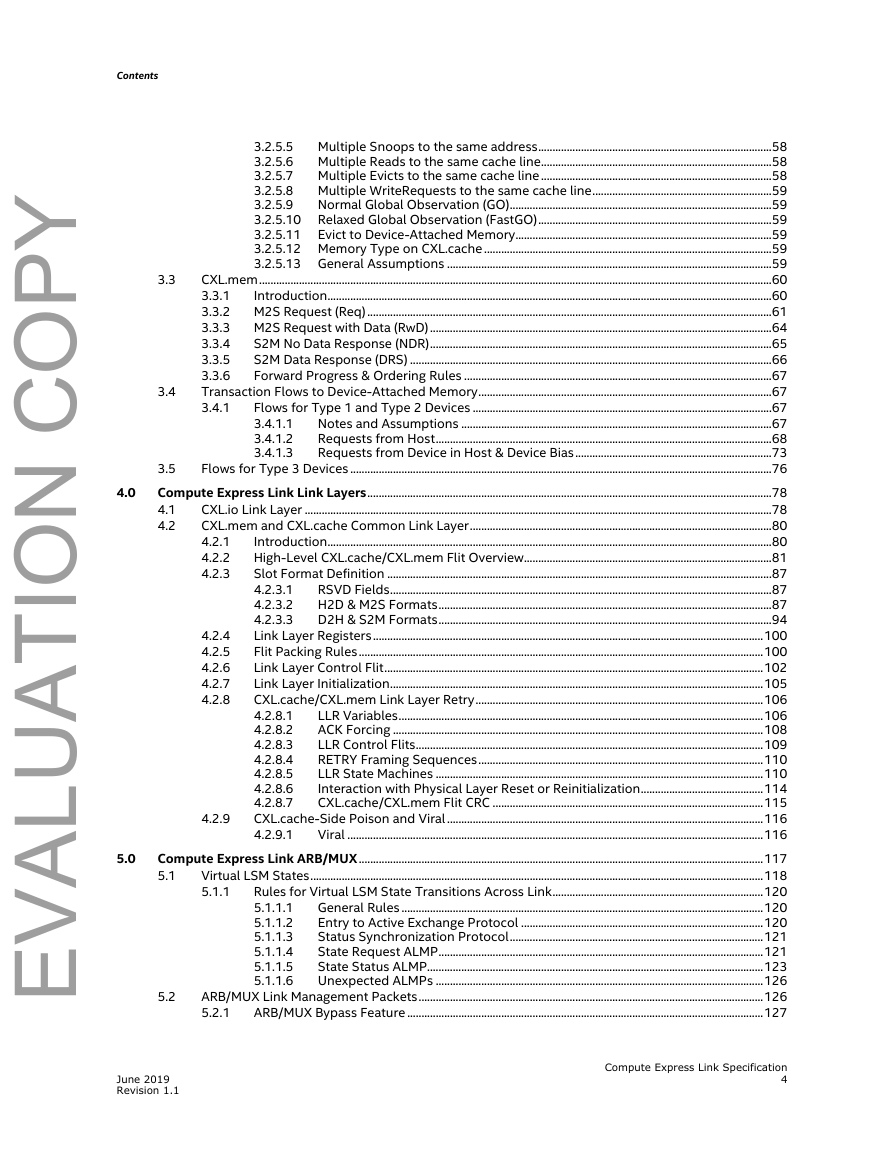
Contents Multiple Snoops to the same address..................................................................................58 3.2.5.5 Multiple Reads to the same cache line.................................................................................58 3.2.5.6 Multiple Evicts to the same cache line.................................................................................58 3.2.5.7 Multiple WriteRequests to the same cache line...............................................................59 3.2.5.8 Normal Global Observation (GO)............................................................................................59 3.2.5.9 Relaxed Global Observation (FastGO)..................................................................................59 3.2.5.10 3.2.5.11 Evict to Device-Attached Memory..........................................................................................59 3.2.5.12 Memory Type on CXL.cache .....................................................................................................59 3.2.5.13 General Assumptions ..................................................................................................................59 CXL.mem....................................................................................................................................................................................60 Introduction............................................................................................................................................................60 3.3.1 M2S Request (Req)..............................................................................................................................................61 3.3.2 M2S Request with Data (RwD)........................................................................................................................64 3.3.3 3.3.4 S2M No Data Response (NDR)........................................................................................................................65 S2M Data Response (DRS) ...............................................................................................................................66 3.3.5 3.3.6 Forward Progress & Ordering Rules ............................................................................................................67 Transaction Flows to Device-Attached Memory.......................................................................................................67 3.4.1 Flows for Type 1 and Type 2 Devices .........................................................................................................67 Notes and Assumptions .............................................................................................................67 3.4.1.1 Requests from Host......................................................................................................................68 3.4.1.2 3.4.1.3 Requests from Device in Host & Device Bias.....................................................................73 Flows for Type 3 Devices ....................................................................................................................................................76 3.5 Compute Express Link Link Layers..............................................................................................................................................78 CXL.io Link Layer ....................................................................................................................................................................78 4.1 CXL.mem and CXL.cache Common Link Layer..........................................................................................................80 4.2 Introduction............................................................................................................................................................80 4.2.1 4.2.2 High-Level CXL.cache/CXL.mem Flit Overview.......................................................................................81 Slot Format Definition .......................................................................................................................................87 4.2.3 RSVD Fields......................................................................................................................................87 4.2.3.1 H2D & M2S Formats.....................................................................................................................87 4.2.3.2 4.2.3.3 D2H & S2M Formats.....................................................................................................................94 Link Layer Registers.........................................................................................................................................100 Flit Packing Rules..............................................................................................................................................100 Link Layer Control Flit.....................................................................................................................................102 Link Layer Initialization...................................................................................................................................105 CXL.cache/CXL.mem Link Layer Retry.....................................................................................................106 LLR Variables................................................................................................................................106 4.2.8.1 ACK Forcing ..................................................................................................................................108 4.2.8.2 LLR Control Flits..........................................................................................................................109 4.2.8.3 RETRY Framing Sequences....................................................................................................110 4.2.8.4 4.2.8.5 LLR State Machines ...................................................................................................................110 Interaction with Physical Layer Reset or Reinitialization...........................................114 4.2.8.6 4.2.8.7 CXL.cache/CXL.mem Flit CRC ...............................................................................................115 CXL.cache-Side Poison and Viral...............................................................................................................116 4.2.9.1 Viral ..................................................................................................................................................116 Compute Express Link ARB/MUX..............................................................................................................................................117 Virtual LSM States...............................................................................................................................................................118 5.1 Rules for Virtual LSM State Transitions Across Link..........................................................................120 5.1.1 General Rules ...............................................................................................................................120 5.1.1.1 5.1.1.2 Entry to Active Exchange Protocol .....................................................................................120 Status Synchronization Protocol.........................................................................................121 5.1.1.3 State Request ALMP..................................................................................................................121 5.1.1.4 State Status ALMP......................................................................................................................123 5.1.1.5 5.1.1.6 Unexpected ALMPs ...................................................................................................................126 ARB/MUX Link Management Packets.........................................................................................................................126 5.2.1 ARB/MUX Bypass Feature .............................................................................................................................127 4.2.4 4.2.5 4.2.6 4.2.7 4.2.8 4.2.9 3.3 3.4 5.2 4.0 5.0 June 2019 Revision 1.1 Compute Express Link Specification 4 EVALUATION COPY
Contents 6.0 7.0 8.0 7.2.2 6.3 6.4 6.5 6.6 6.7 7.2 6.3.1.3 5.3 Arbitration and Data Multiplexing/Demultiplexing ..............................................................................................128 Flex Bus Physical Layer ..................................................................................................................................................................129 6.1 Overview .................................................................................................................................................................................129 Flex Bus.CXL Framing and Packet Layout.................................................................................................................130 6.2 Ordered Set Blocks and Data Blocks........................................................................................................130 6.2.1 Protocol ID[15:0]...............................................................................................................................................131 6.2.2 x16 Packet Layout ............................................................................................................................................132 6.2.3 6.2.4 x8 Packet Layout...............................................................................................................................................133 x4 Packet Layout...............................................................................................................................................136 6.2.5 x2 Packet Layout...............................................................................................................................................136 6.2.6 x1 Packet Layout...............................................................................................................................................136 6.2.7 6.2.8 Special Case: CXL.io -- When a TLP Ends on a Flit Boundary........................................................136 6.2.9 Framing Errors....................................................................................................................................................137 Link Training..........................................................................................................................................................................138 PCIe vs Flex Bus.CXL mode selection.......................................................................................................138 6.3.1 Hardware Autonomous Mode Negotiation .....................................................................139 6.3.1.1 6.3.1.2 Flex Bus.CXL Negotiation with Maximum Supported Link Speed of 8GT/s or 16GT/s .....................................................................................................142 Link Width Degradation and Speed Downgrade ..........................................................143 Recovery.Idle and Config.Idle Transitions to L0 ....................................................................................................143 L1 Abort Scenario ...............................................................................................................................................................143 Exit from Recovery..............................................................................................................................................................143 Retimers and Low Latency Mode .................................................................................................................................143 6.7.1 Control SKP Ordered Set Frequency and L1/Recovery Entry .......................................................144 Control and Status Registers.......................................................................................................................................................145 7.1 Configuration Space Registers ......................................................................................................................................145 7.1.1 PCI Express Designated Vendor-Specific Extended Capability (DVSEC) for CXL Device............................................................................................................145 DVSEC Flex Bus Capability (Offset 0Ah)...........................................................................147 7.1.1.1 7.1.1.2 DVSEC Flex Bus Control (Offset 0Ch) ................................................................................147 DVSEC Flex Bus Status (Offset 0Eh)...................................................................................148 7.1.1.3 DVSEC Flex Bus Control2 (Offset 10h)..............................................................................148 7.1.1.4 DVSEC Flex Bus Status2 (Offset 12h)................................................................................148 7.1.1.5 DVSEC Flex Bus Lock (Offset 14h) ......................................................................................148 7.1.1.6 7.1.1.7 DVSEC Flex Bus Range registers..........................................................................................148 Memory Mapped Registers .............................................................................................................................................150 Upstream and Downstream Port Registers ...........................................................................................152 7.2.1 CXL Downstream Port RCRB .................................................................................................152 7.2.1.1 CXL Upstream Port RCRB .......................................................................................................154 7.2.1.2 7.2.1.3 Upstream and Downstream Flex Bus Port DVSEC.......................................................156 CXL Upstream and Downstream Port Subsystem Component Registers................................158 CXL.cache and CXL.mem Registers ....................................................................................158 7.2.2.1 7.2.2.2 CXL ARB/MUX Registers..........................................................................................................166 CXL RCRB Base Register...................................................................................................................................................167 7.3 Reset, Initialization, Configuration and Manageability ..................................................................................................168 Compute Express Link Boot and Reset Overview .................................................................................................168 8.1 General ..................................................................................................................................................................168 8.1.1 8.1.2 Comparing CXL and PCIe behavior...........................................................................................................168 Compute Express Link Device Boot Flow .................................................................................................................169 Compute Express Link Device Warm Reset Entry Flow......................................................................................169 Compute Express Link Device Cold Reset Entry Flow.........................................................................................170 Compute Express Link Device Sleep State Entry Flow .......................................................................................171 Function Level Reset (FLR) ..............................................................................................................................................172 Hotplug....................................................................................................................................................................................172 8.2 8.3 8.4 8.5 8.6 8.7 June 2019 Revision 1.1 Compute Express Link Specification 5 EVALUATION COPY
Contents 9.0 8.8 8.9 8.10 9.3 9.4 Software Enumeration ......................................................................................................................................................173 Software Model..................................................................................................................................................173 8.8.1 PCIe Software View of the Hierarchy........................................................................................................173 8.8.2 8.8.2.1 BIOS View ......................................................................................................................................174 8.8.2.2 OS View ..........................................................................................................................................174 BIOS Enumeration Flow.................................................................................................................................174 8.8.3 8.8.4 Software View of CXL.cache.........................................................................................................................176 Accelerators with Multiple Flex Bus Links ................................................................................................................177 Single CPU Topology ......................................................................................................................................177 8.9.1 8.9.2 Multiple CPU Topology ..................................................................................................................................178 Software View of HDM ......................................................................................................................................................179 8.10.1 Accelerator HMAT Fragment Table Format ..........................................................................................180 8.11 Manageability Model for CXL Devices Matches PCIe...........................................................................................180 Power Management..........................................................................................................................................................................181 Statement of Requirements............................................................................................................................................181 9.1 Policy based Runtime Control - Idle Power - Protocol Flow............................................................................181 9.2 9.2.1 General ..................................................................................................................................................................181 Package-Level Idle (C-state) Entry and Exit Coordination ..............................................................181 9.2.2 PkgC Entry flows ...............................................................................................................................................183 9.2.3 9.2.4 PkgC Exit Flows..................................................................................................................................................184 Compute Express Link Physical Layer Power Management States...............................................................185 Compute Express Link Power Management............................................................................................................186 Compute Express Link PM Entry Phase 1...............................................................................................186 9.4.1 Compute Express Link PM Entry Phase 2...............................................................................................186 9.4.2 9.4.3 Compute Express Link PM Entry Phase 3...............................................................................................188 9.4.4 Compute Express Link Exit from ASPM L1 ............................................................................................190 CXL.io Link Power Management ...................................................................................................................................190 CXL.io ASPM Phase L1 Entry........................................................................................................................190 9.5.1 CXL.io ASPM Phase 2 Entry..........................................................................................................................191 9.5.2 9.5.3 CXL.io ASPM Phase 3 Entry..........................................................................................................................191 CXL.cache + CXL.mem Link Power Management ..................................................................................................192 10.0 Security...................................................................................................................................................................................................193 11.0 Reliability, Availability and Serviceability ............................................................................................................................194 Supported RAS Features..................................................................................................................................................194 CXL Error Handling.............................................................................................................................................................194 11.2.1 Protocol and Link Layer Error Reporting................................................................................................195 CXL Downstream Port (DP) Detected Errors ..................................................................195 11.2.2 CXL Device Error Handling............................................................................................................................196 CXL.mem and CXL.cache Errors...........................................................................................196 CXL Device Error Handling Flows........................................................................................197 CXL Link Down Handling..................................................................................................................................................198 CXL Viral Handling..............................................................................................................................................................198 CXL Error Injection..............................................................................................................................................................199 12.0 Platform Architecture......................................................................................................................................................................200 Flex Bus connector definition ........................................................................................................................................200 12.1.1 Connector Type.................................................................................................................................................200 12.1.2 Pin Count..............................................................................................................................................................200 Topologies..............................................................................................................................................................................202 Protocol Detection..............................................................................................................................................................202 AIC Form Factor ...................................................................................................................................................................202 AIC Power Envelope...........................................................................................................................................................202 Flexbus Slot Auxiliary Power..........................................................................................................................................202 12.2 12.3 12.4 12.5 12.6 11.2.2.1 11.2.2.2 11.3 11.4 11.5 12.1 9.5 9.6 11.1 11.2 11.2.1.1 June 2019 Revision 1.1 Compute Express Link Specification 6 EVALUATION COPY
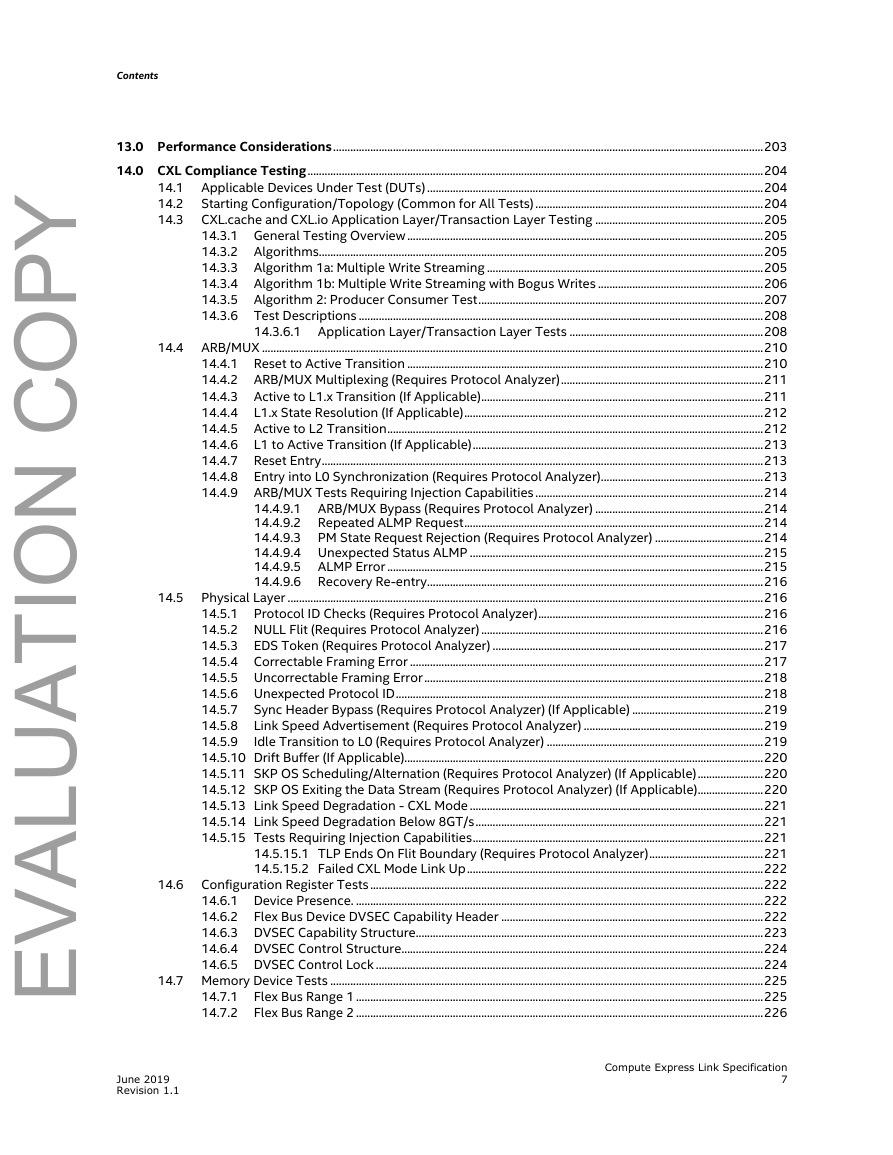
Contents 14.1 14.2 14.3 13.0 Performance Considerations.......................................................................................................................................................203 14.0 CXL Compliance Testing................................................................................................................................................................204 Applicable Devices Under Test (DUTs) ......................................................................................................................204 Starting Configuration/Topology (Common for All Tests)................................................................................204 CXL.cache and CXL.io Application Layer/Transaction Layer Testing ...........................................................205 14.3.1 General Testing Overview .............................................................................................................................205 14.3.2 Algorithms............................................................................................................................................................205 14.3.3 Algorithm 1a: Multiple Write Streaming .................................................................................................205 14.3.4 Algorithm 1b: Multiple Write Streaming with Bogus Writes ..........................................................206 14.3.5 Algorithm 2: Producer Consumer Test....................................................................................................207 14.3.6 Test Descriptions ..............................................................................................................................................208 14.3.6.1 Application Layer/Transaction Layer Tests ....................................................................208 ARB/MUX ................................................................................................................................................................................210 14.4.1 Reset to Active Transition .............................................................................................................................210 14.4.2 ARB/MUX Multiplexing (Requires Protocol Analyzer).......................................................................211 14.4.3 Active to L1.x Transition (If Applicable)...................................................................................................211 14.4.4 L1.x State Resolution (If Applicable).........................................................................................................212 14.4.5 Active to L2 Transition....................................................................................................................................212 14.4.6 L1 to Active Transition (If Applicable)......................................................................................................213 14.4.7 Reset Entry...........................................................................................................................................................213 14.4.8 Entry into L0 Synchronization (Requires Protocol Analyzer).........................................................213 14.4.9 ARB/MUX Tests Requiring Injection Capabilities ................................................................................214 14.4.9.1 ARB/MUX Bypass (Requires Protocol Analyzer) ...........................................................214 Repeated ALMP Request.........................................................................................................214 14.4.9.2 14.4.9.3 PM State Request Rejection (Requires Protocol Analyzer) ......................................214 14.4.9.4 Unexpected Status ALMP .......................................................................................................215 14.4.9.5 ALMP Error ....................................................................................................................................215 14.4.9.6 Recovery Re-entry......................................................................................................................216 Physical Layer .......................................................................................................................................................................216 14.5.1 Protocol ID Checks (Requires Protocol Analyzer)...............................................................................216 14.5.2 NULL Flit (Requires Protocol Analyzer) ...................................................................................................216 14.5.3 EDS Token (Requires Protocol Analyzer) ...............................................................................................217 14.5.4 Correctable Framing Error ............................................................................................................................217 14.5.5 Uncorrectable Framing Error.......................................................................................................................218 14.5.6 Unexpected Protocol ID.................................................................................................................................218 Sync Header Bypass (Requires Protocol Analyzer) (If Applicable) ..............................................219 14.5.7 Link Speed Advertisement (Requires Protocol Analyzer) ...............................................................219 14.5.8 14.5.9 Idle Transition to L0 (Requires Protocol Analyzer) ............................................................................219 14.5.10 Drift Buffer (If Applicable)..............................................................................................................................220 14.5.11 SKP OS Scheduling/Alternation (Requires Protocol Analyzer) (If Applicable).......................220 14.5.12 SKP OS Exiting the Data Stream (Requires Protocol Analyzer) (If Applicable).......................220 14.5.13 Link Speed Degradation - CXL Mode .......................................................................................................221 14.5.14 Link Speed Degradation Below 8GT/s.....................................................................................................221 14.5.15 Tests Requiring Injection Capabilities......................................................................................................221 14.5.15.1 TLP Ends On Flit Boundary (Requires Protocol Analyzer)........................................221 14.5.15.2 Failed CXL Mode Link Up........................................................................................................222 Configuration Register Tests..........................................................................................................................................222 14.6.1 Device Presence. ...............................................................................................................................................222 14.6.2 Flex Bus Device DVSEC Capability Header ............................................................................................222 14.6.3 DVSEC Capability Structure..........................................................................................................................223 14.6.4 DVSEC Control Structure...............................................................................................................................224 14.6.5 DVSEC Control Lock ........................................................................................................................................224 14.7 Memory Device Tests ........................................................................................................................................................225 Flex Bus Range 1 ...............................................................................................................................................225 Flex Bus Range 2 ...............................................................................................................................................226 14.7.1 14.7.2 14.4 14.5 14.6 June 2019 Revision 1.1 Compute Express Link Specification 7 EVALUATION COPY
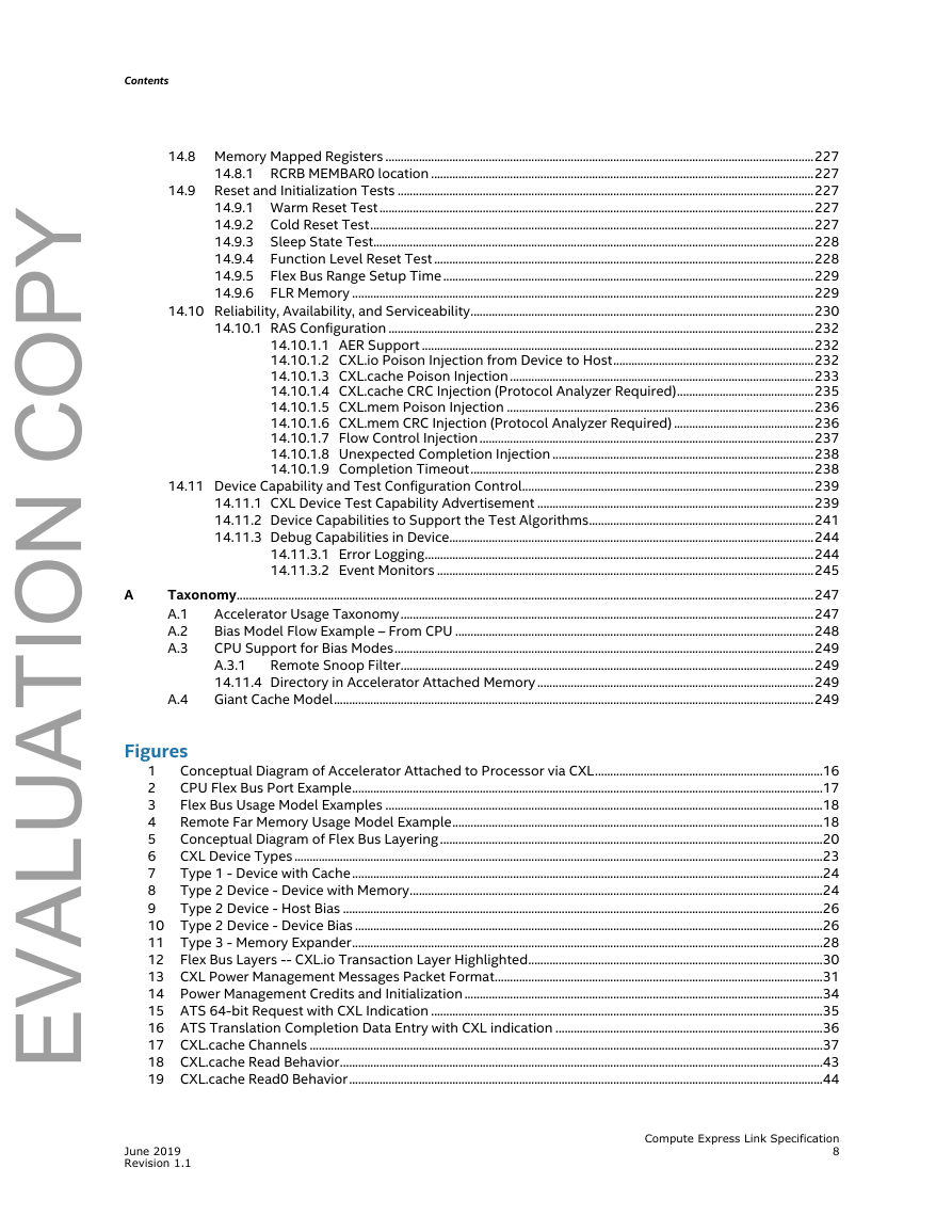
Contents 14.9 14.8 Memory Mapped Registers .............................................................................................................................................227 14.8.1 RCRB MEMBAR0 location ..............................................................................................................................227 Reset and Initialization Tests .........................................................................................................................................227 14.9.1 Warm Reset Test...............................................................................................................................................227 14.9.2 Cold Reset Test..................................................................................................................................................227 Sleep State Test.................................................................................................................................................228 14.9.3 Function Level Reset Test .............................................................................................................................228 14.9.4 14.9.5 Flex Bus Range Setup Time..........................................................................................................................229 FLR Memory ........................................................................................................................................................229 14.9.6 14.10 Reliability, Availability, and Serviceability.................................................................................................................230 14.10.1 RAS Configuration ............................................................................................................................................232 14.10.1.1 AER Support .................................................................................................................................232 14.10.1.2 CXL.io Poison Injection from Device to Host..................................................................232 14.10.1.3 CXL.cache Poison Injection....................................................................................................233 14.10.1.4 CXL.cache CRC Injection (Protocol Analyzer Required).............................................235 14.10.1.5 CXL.mem Poison Injection .....................................................................................................236 14.10.1.6 CXL.mem CRC Injection (Protocol Analyzer Required) ..............................................236 14.10.1.7 Flow Control Injection..............................................................................................................237 14.10.1.8 Unexpected Completion Injection ......................................................................................238 14.10.1.9 Completion Timeout.................................................................................................................238 14.11 Device Capability and Test Configuration Control................................................................................................239 14.11.1 CXL Device Test Capability Advertisement ...........................................................................................239 14.11.2 Device Capabilities to Support the Test Algorithms..........................................................................241 14.11.3 Debug Capabilities in Device........................................................................................................................244 14.11.3.1 Error Logging................................................................................................................................244 14.11.3.2 Event Monitors ............................................................................................................................245 Taxonomy..............................................................................................................................................................................................247 Accelerator Usage Taxonomy........................................................................................................................................247 A.1 Bias Model Flow Example – From CPU ......................................................................................................................248 A.2 CPU Support for Bias Modes..........................................................................................................................................249 A.3 A.3.1 Remote Snoop Filter........................................................................................................................................249 14.11.4 Directory in Accelerator Attached Memory...........................................................................................249 Giant Cache Model..............................................................................................................................................................249 A.4 A Figures 1 Conceptual Diagram of Accelerator Attached to Processor via CXL...........................................................................16 2 CPU Flex Bus Port Example...........................................................................................................................................................17 3 Flex Bus Usage Model Examples ................................................................................................................................................18 4 Remote Far Memory Usage Model Example..........................................................................................................................18 5 Conceptual Diagram of Flex Bus Layering..............................................................................................................................20 6 CXL Device Types ..............................................................................................................................................................................23 7 Type 1 - Device with Cache...........................................................................................................................................................24 8 Type 2 Device - Device with Memory........................................................................................................................................24 9 Type 2 Device - Host Bias ..............................................................................................................................................................26 10 Type 2 Device - Device Bias ..........................................................................................................................................................26 11 Type 3 - Memory Expander...........................................................................................................................................................28 12 Flex Bus Layers -- CXL.io Transaction Layer Highlighted.................................................................................................30 13 CXL Power Management Messages Packet Format............................................................................................................31 14 Power Management Credits and Initialization ......................................................................................................................34 15 ATS 64-bit Request with CXL Indication .................................................................................................................................35 16 ATS Translation Completion Data Entry with CXL indication ........................................................................................36 17 CXL.cache Channels .........................................................................................................................................................................37 18 CXL.cache Read Behavior...............................................................................................................................................................43 19 CXL.cache Read0 Behavior............................................................................................................................................................44 June 2019 Revision 1.1 Compute Express Link Specification 8 EVALUATION COPY
分享到:
收藏