DDS Compiler v6.0
LogiCORE IP Product Guide
Vivado Design Suite
PG141 December 20, 2017
�
Table of Contents
IP Facts
Chapter 1: Overview
Applications . . . . . . . . . . . . . . . . . . . . . . . . . . . . . . . . . . . . . . . . . . . . . . . . . . . . . . . . . . . . . . . . . . . . . . 5
Licensing and Ordering . . . . . . . . . . . . . . . . . . . . . . . . . . . . . . . . . . . . . . . . . . . . . . . . . . . . . . . . . . . . . 5
Chapter 2: Product Specification
Performance. . . . . . . . . . . . . . . . . . . . . . . . . . . . . . . . . . . . . . . . . . . . . . . . . . . . . . . . . . . . . . . . . . . . . . 8
Resource Utilization. . . . . . . . . . . . . . . . . . . . . . . . . . . . . . . . . . . . . . . . . . . . . . . . . . . . . . . . . . . . . . . . 8
Port Descriptions . . . . . . . . . . . . . . . . . . . . . . . . . . . . . . . . . . . . . . . . . . . . . . . . . . . . . . . . . . . . . . . . . . 8
Chapter 3: Designing with the Core
General Description . . . . . . . . . . . . . . . . . . . . . . . . . . . . . . . . . . . . . . . . . . . . . . . . . . . . . . . . . . . . . . . 11
Theory of Operation . . . . . . . . . . . . . . . . . . . . . . . . . . . . . . . . . . . . . . . . . . . . . . . . . . . . . . . . . . . . . . 11
Multichannel . . . . . . . . . . . . . . . . . . . . . . . . . . . . . . . . . . . . . . . . . . . . . . . . . . . . . . . . . . . . . . . . . . . . 26
Design Examples . . . . . . . . . . . . . . . . . . . . . . . . . . . . . . . . . . . . . . . . . . . . . . . . . . . . . . . . . . . . . . . . . 26
Clocking. . . . . . . . . . . . . . . . . . . . . . . . . . . . . . . . . . . . . . . . . . . . . . . . . . . . . . . . . . . . . . . . . . . . . . . . . 27
Resets . . . . . . . . . . . . . . . . . . . . . . . . . . . . . . . . . . . . . . . . . . . . . . . . . . . . . . . . . . . . . . . . . . . . . . . . . . 27
Protocol Description . . . . . . . . . . . . . . . . . . . . . . . . . . . . . . . . . . . . . . . . . . . . . . . . . . . . . . . . . . . . . . 29
Chapter 4: Design Flow Steps
Customizing and Generating the Core . . . . . . . . . . . . . . . . . . . . . . . . . . . . . . . . . . . . . . . . . . . . . . . . 38
System Generator for DSP. . . . . . . . . . . . . . . . . . . . . . . . . . . . . . . . . . . . . . . . . . . . . . . . . . . . . . . . . . 49
Constraining the Core . . . . . . . . . . . . . . . . . . . . . . . . . . . . . . . . . . . . . . . . . . . . . . . . . . . . . . . . . . . . . 50
Simulation . . . . . . . . . . . . . . . . . . . . . . . . . . . . . . . . . . . . . . . . . . . . . . . . . . . . . . . . . . . . . . . . . . . . . . 51
Synthesis and Implementation . . . . . . . . . . . . . . . . . . . . . . . . . . . . . . . . . . . . . . . . . . . . . . . . . . . . . . 51
Chapter 5: C Model
Features . . . . . . . . . . . . . . . . . . . . . . . . . . . . . . . . . . . . . . . . . . . . . . . . . . . . . . . . . . . . . . . . . . . . . . . . 52
Overview . . . . . . . . . . . . . . . . . . . . . . . . . . . . . . . . . . . . . . . . . . . . . . . . . . . . . . . . . . . . . . . . . . . . . . . 52
Installation . . . . . . . . . . . . . . . . . . . . . . . . . . . . . . . . . . . . . . . . . . . . . . . . . . . . . . . . . . . . . . . . . . . . . . 54
C Model Interface. . . . . . . . . . . . . . . . . . . . . . . . . . . . . . . . . . . . . . . . . . . . . . . . . . . . . . . . . . . . . . . . . 54
Data Format . . . . . . . . . . . . . . . . . . . . . . . . . . . . . . . . . . . . . . . . . . . . . . . . . . . . . . . . . . . . . . . . . . . . . 58
DDS Compiler v6.0
PG141 December 20, 2017
www.xilinx.com
2
Send Feedback�
Compiling . . . . . . . . . . . . . . . . . . . . . . . . . . . . . . . . . . . . . . . . . . . . . . . . . . . . . . . . . . . . . . . . . . . . . . . 58
Linking. . . . . . . . . . . . . . . . . . . . . . . . . . . . . . . . . . . . . . . . . . . . . . . . . . . . . . . . . . . . . . . . . . . . . . . . . . 59
Example . . . . . . . . . . . . . . . . . . . . . . . . . . . . . . . . . . . . . . . . . . . . . . . . . . . . . . . . . . . . . . . . . . . . . . . . 59
MATLAB Interface . . . . . . . . . . . . . . . . . . . . . . . . . . . . . . . . . . . . . . . . . . . . . . . . . . . . . . . . . . . . . . . . 60
Chapter 6: Test Bench
Demonstration Test Bench . . . . . . . . . . . . . . . . . . . . . . . . . . . . . . . . . . . . . . . . . . . . . . . . . . . . . . . . . 63
Appendix A: Upgrading
Migrating to the Vivado Design Suite. . . . . . . . . . . . . . . . . . . . . . . . . . . . . . . . . . . . . . . . . . . . . . . . . 66
Upgrading in the Vivado Design Suite . . . . . . . . . . . . . . . . . . . . . . . . . . . . . . . . . . . . . . . . . . . . . . . . 66
Appendix B: Debugging
Finding Help on Xilinx.com . . . . . . . . . . . . . . . . . . . . . . . . . . . . . . . . . . . . . . . . . . . . . . . . . . . . . . . . . 72
Debug Tools . . . . . . . . . . . . . . . . . . . . . . . . . . . . . . . . . . . . . . . . . . . . . . . . . . . . . . . . . . . . . . . . . . . . . 73
AXI4-Stream Interface Debug . . . . . . . . . . . . . . . . . . . . . . . . . . . . . . . . . . . . . . . . . . . . . . . . . . . . . . . 74
Appendix C: Additional Resources and Legal Notices
Xilinx Resources . . . . . . . . . . . . . . . . . . . . . . . . . . . . . . . . . . . . . . . . . . . . . . . . . . . . . . . . . . . . . . . . . . 75
Documentation Navigator and Design Hubs . . . . . . . . . . . . . . . . . . . . . . . . . . . . . . . . . . . . . . . . . . . 75
References . . . . . . . . . . . . . . . . . . . . . . . . . . . . . . . . . . . . . . . . . . . . . . . . . . . . . . . . . . . . . . . . . . . . . . 76
Revision History . . . . . . . . . . . . . . . . . . . . . . . . . . . . . . . . . . . . . . . . . . . . . . . . . . . . . . . . . . . . . . . . . . 77
Please Read: Important Legal Notices . . . . . . . . . . . . . . . . . . . . . . . . . . . . . . . . . . . . . . . . . . . . . . . . 78
DDS Compiler v6.0
PG141 December 20, 2017
www.xilinx.com
3
Send Feedback�
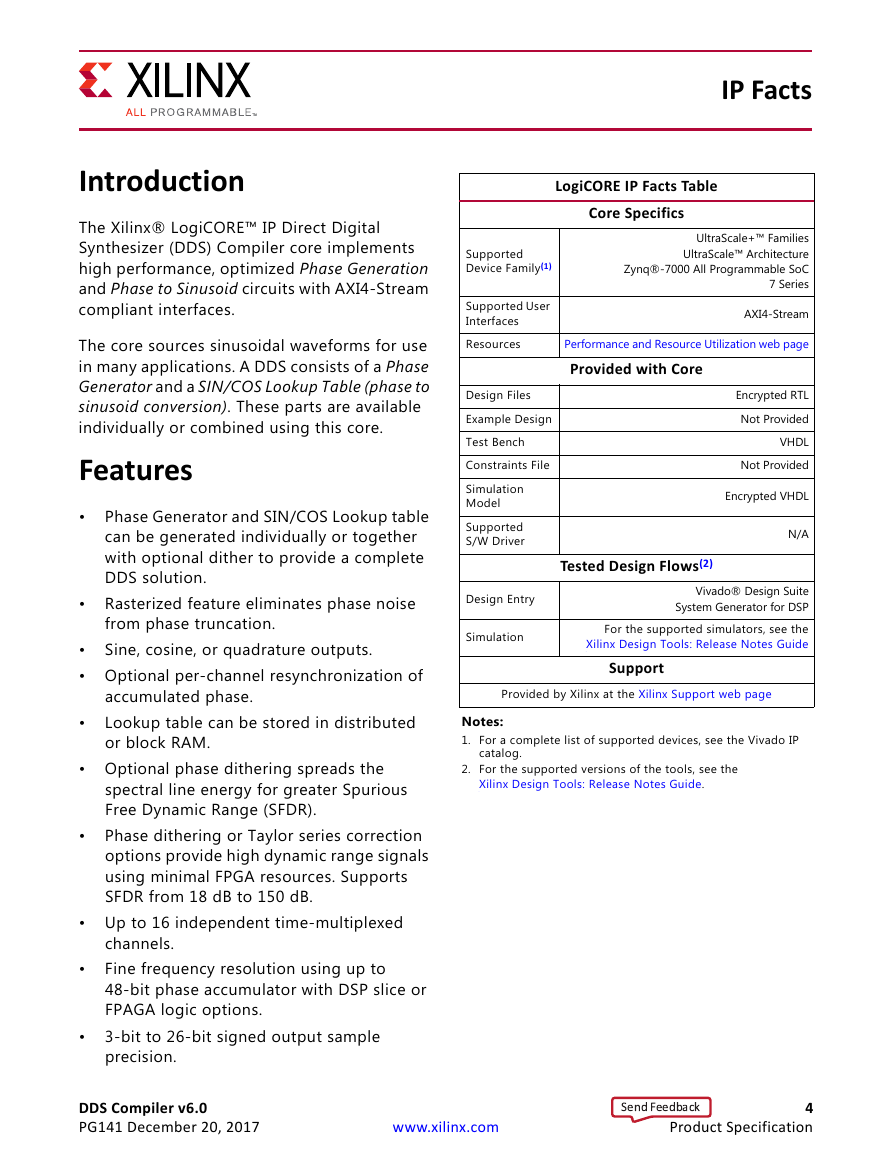
IP Facts
LogiCORE IP Facts Table
Core Specifics
UltraScale+™ Families
UltraScale™ Architecture
Zynq®-7000 All Programmable SoC
7 Series
AXI4-Stream
Performance and Resource Utilization web page
Provided with Core
Encrypted RTL
Not Provided
VHDL
Not Provided
Encrypted VHDL
N/A
Supported
Device Family(1)
Supported User
Interfaces
Resources
Design Files
Example Design
Test Bench
Constraints File
Simulation
Model
Supported
S/W Driver
Tested Design Flows(2)
Design Entry
Simulation
Vivado® Design Suite
System Generator for DSP
For the supported simulators, see the
Xilinx Design Tools: Release Notes Guide
Support
Provided by Xilinx at the Xilinx Support web page
Notes:
1. For a complete list of supported devices, see the Vivado IP
catalog.
2. For the supported versions of the tools, see the
Xilinx Design Tools: Release Notes Guide.
Introduction
The Xilinx® LogiCORE™ IP Direct Digital
Synthesizer (DDS) Compiler core implements
high performance, optimized Phase Generation
and Phase to Sinusoid circuits with AXI4-Stream
compliant interfaces.
The core sources sinusoidal waveforms for use
in many applications. A DDS consists of a Phase
Generator and a SIN/COS Lookup Table (phase to
sinusoid conversion). These parts are available
individually or combined using this core.
Features
•
Phase Generator and SIN/COS Lookup table
can be generated individually or together
with optional dither to provide a complete
DDS solution.
Rasterized feature eliminates phase noise
from phase truncation.
Sine, cosine, or quadrature outputs.
•
• Optional per-channel resynchronization of
accumulated phase.
Lookup table can be stored in distributed
or block RAM.
• Optional phase dithering spreads the
spectral line energy for greater Spurious
Free Dynamic Range (SFDR).
Phase dithering or Taylor series correction
options provide high dynamic range signals
using minimal FPGA resources. Supports
SFDR from 18 dB to 150 dB.
•
•
•
•
•
• Up to 16 independent time-multiplexed
channels.
Fine frequency resolution using up to
48-bit phase accumulator with DSP slice or
FPAGA logic options.
3-bit to 26-bit signed output sample
precision.
DDS Compiler v6.0
PG141 December 20, 2017
www.xilinx.com
4
Product Specification
Send Feedback�
Chapter 1
Overview
Direct digital synthesizers (DDS), or numerically controlled oscillators (NCO), are important
components in many digital communication systems. Quadrature synthesizers are used for
constructing digital down and up converters, demodulators, and implementing various
types of modulation schemes, including PSK (phase shift keying), FSK (frequency shift
keying), and MSK (minimum shift keying). A common method for digitally generating a
complex or real valued sinusoid employs a lookup table scheme. The lookup table stores
samples of a sinusoid. A digital integrator is used to generate a suitable phase argument
that is mapped by the lookup table to the desired output waveform. A simple user interface
accepts system-level parameters such as the desired output frequency and spur
suppression of the generated waveforms.
Software-defined radios (SDR)
Applications
• Digital radios and modems
•
• Digital down/up converters for cellular and PCS base stations
• Waveform synthesis in digital phase locked loops
• Generating injection frequencies for analog mixers
Licensing and Ordering
This Xilinx® LogiCORE™ IP module is provided at no additional cost with the Xilinx
Vivado® Design Suite under the terms of the Xilinx End User License.
Information about other Xilinx LogiCORE IP modules is available at the Xilinx Intellectual
Property page. For information about pricing and availability of other Xilinx LogiCORE IP
modules and tools, contact your local Xilinx sales representative.
DDS Compiler v6.0
PG141 December 20, 2017
www.xilinx.com
5
Send Feedback�
Chapter 2
Product Specification
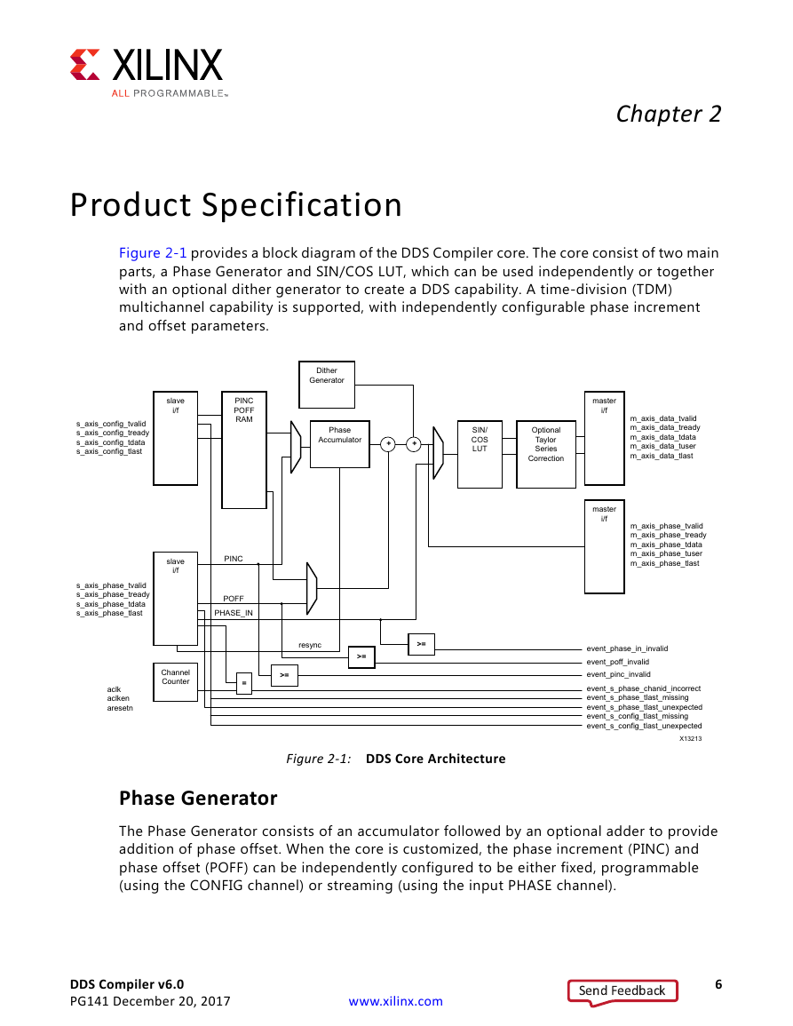
Figure 2-1 provides a block diagram of the DDS Compiler core. The core consist of two main
parts, a Phase Generator and SIN/COS LUT, which can be used independently or together
with an optional dither generator to create a DDS capability. A time-division (TDM)
multichannel capability is supported, with independently configurable phase increment
and offset parameters.
X-Ref Target - Figure 2-1
s_axis_config_tvalid
s_axis_config_tready
s_axis_config_tdata
s_axis_config_tlast
Dither
Generator
slave
i/f
PINC
POFF
RAM
Phase
Accumulator
+
+
SIN/
COS
LUT
Optional
Taylor
Series
Correction
s_axis_phase_tvalid
s_axis_phase_tready
s_axis_phase_tdata
s_axis_phase_tlast
slave
i/f
PINC
POFF
PHASE_IN
resync
>=
>=
Channel
Counter
>=
=
aclk
aclken
aresetn
master
i/f
master
i/f
m_axis_data_tvalid
m_axis_data_tready
m_axis_data_tdata
m_axis_data_tuser
m_axis_data_tlast
m_axis_phase_tvalid
m_axis_phase_tready
m_axis_phase_tdata
m_axis_phase_tuser
m_axis_phase_tlast
event_phase_in_invalid
event_poff_invalid
event_pinc_invalid
event_s_phase_chanid_incorrect
event_s_phase_tlast_missing
event_s_phase_tlast_unexpected
event_s_config_tlast_missing
event_s_config_tlast_unexpected
X13213
Figure 2-1: DDS Core Architecture
Phase Generator
The Phase Generator consists of an accumulator followed by an optional adder to provide
addition of phase offset. When the core is customized, the phase increment (PINC) and
phase offset (POFF) can be independently configured to be either fixed, programmable
(using the CONFIG channel) or streaming (using the input PHASE channel).
DDS Compiler v6.0
PG141 December 20, 2017
www.xilinx.com
6
Send Feedback�
Chapter 2:
Product Specification
When set to fixed, the DDS output frequency is set when the core is customized and cannot
be adjusted after the core is embedded in a design.
When set to programmable, the CONFIG channel TDATA field has a subfield for the input in
question (PINC or POFF) or both if both have been selected to be programmable. If neither
PINC nor POFF is set to programmable, there is no CONFIG channel.
When set to streaming, the input PHASE channel TDATA field has a subfield for the input in
question (PINC or POFF) or both if both have been selected to be streaming. If neither PINC
nor POFF is set to streaming, and the core is configured to have a Phase Generator, then
there is no input PHASE channel.
When PINC is set to streaming, an optional RESYNC streaming input can be configured.
When asserted, this signal resets the accumulated phase of the channel in question.
When rasterized mode is selected, the hardware values of PINC and POFF that are input or
configured must be 0 to Modulus-1. This corresponds to a full circle. So for negative PINC
or POFF values, add the Modulus to the negative value desired to map to the required
range. For example with Modulus = 100, the required range is 0 to 99. An angle of -90°
would be -25 with this Modulus. Adding 100 gives 75 (270°).
When using system parameters, PINC and POFF are not input directly, but are calculated
from the input Output Frequencies and Phase Angles. Beware that for small values of
Modulus, the available values are relatively far apart, so the actual output frequency or
phase angle may differ significantly from the desired value as displayed in the Additional
Summary tab.
SIN/COS LUT
When configured as a SIN/COS LUT only, the Phase Generator is not implemented and the
PHASE_IN signal is input using the input PHASE channel and transformed into sine and
cosine outputs using a look-up table. Efficient memory usage is achieved by exploiting the
symmetry of sinusoid waveforms. The core can be configured for sine only output, cosine
only output or both (quadrature) output. Each output can be configured independently to
be negated. Precision can be increased using optional Taylor series correction. This exploits
DSP slices on FPGA families that support them to achieve high SFDR with high speed
operation.
Phase Generator and SIN/COS LUT (DDS)
The Phase Generator is used in conjunction with the SIN/COS LUT to provide either a phase
truncated DDS or Taylor series corrected DDS. An optional dither generator can be added
between the two blocks to provide a phase dithered DDS.
DDS Compiler v6.0
PG141 December 20, 2017
www.xilinx.com
7
Send Feedback�
Chapter 2:
Product Specification
Performance
This section details the performance information for various core configurations.
Latency
The latency of the core can be specified through the user interface in the Vivado Integrated
Design Environment (IDE) or be automatically set to the optimum value based upon the
Optimization Goal.
For streaming inputs (s_axis_phase_t*) the latency specifies the minimum number of
cycles between input and the associated output.
For configuration inputs, the latency is the minimum latency from the first cycle aresetn
becomes inactive until a valid output. The latency from configuration channel inputs to
output channel outputs is not deterministic because configuration inputs are synchronized
to the internal channel counter phase, thus introducing a delay which is unknown external
to the core.
IMPORTANT: Xilinx recommends that CE and TVALID on input are not both used to control data into
the core as this can lead to obscure latency. For instance if TREADY is not used, data samples are pushed
through the core by TVALID on input and hence setting TVALID Low freezes data in transit much like
clock enable. Xilinx recommends that full AXI4-Stream protocol is used where latency is variable, but
no data is lost. If deterministic latency is required, Xilinx recommends that you fix either CE or TVALID
High and control data flow using the other.
Throughput
The DDS Compiler core supports full throughput in all configurations (one output for every
cycle).
Resource Utilization
For details about resource utilization, visit Performance and Resource Utilization.
Port Descriptions
The DDS Compiler core pinout is shown in Figure 2-2. All of the possible pins are shown,
though the specific pins in any instance depend upon parameters specified when the core
is generated.
DDS Compiler v6.0
PG141 December 20, 2017
www.xilinx.com
8
Send Feedback�





 2023年江西萍乡中考道德与法治真题及答案.doc
 2012年重庆南川中考生物真题及答案.doc
 2013年江西师范大学地理学综合及文艺理论基础考研真题.doc
 2020年四川甘孜小升初语文真题及答案I卷.doc
 2020年注册岩土工程师专业基础考试真题及答案.doc
 2023-2024学年福建省厦门市九年级上学期数学月考试题及答案.doc
 2021-2022学年辽宁省沈阳市大东区九年级上学期语文期末试题及答案.doc
 2022-2023学年北京东城区初三第一学期物理期末试卷及答案.doc
 2018上半年江西教师资格初中地理学科知识与教学能力真题及答案.doc
 2012年河北国家公务员申论考试真题及答案-省级.doc
 2020-2021学年江苏省扬州市江都区邵樊片九年级上学期数学第一次质量检测试题及答案.doc
 2022下半年黑龙江教师资格证中学综合素质真题及答案.doc