Proceedings of the 34th Chinese Control Conference
July 28-30, 2015, Hangzhou, China
Controller Design for a Permanent Magnet Linear
Synchronous Motor: a Singular Perturbation Method
YANG Chunyu, HAN Yuchen, SHI Yuxiang, ZHOU Linna
School of Information and Electrical Engineering, China University of Mining and Technology, Xuzhou 221116, P. R. China
E-mail: chunyuyang@cumt.edu.cn, han19900206@sina.com, zs13060105@cumt.edu.cn, linnazhou@cumt.edu.cn
Abstract: This paper considers the design problem of a three-closed-loop controller for a permanent magnet linear synchronous
motor. Taking into account the multiple time-scale property of the system, the design is achieved in two stages. In the first one,
the inner loop (current-loop) controller is designed based on the singular perturbation theory and pole assignment technique. The
controller gains can be constructed by solving a set of well-defined linear matrix inequalities. In the second stage, with the ob-
tained controller gains, a homotopy algorithm is formulated to design the velocity- and position-loop controllers simultaneously.
Simulation is given to illustrate the proposed results.
Key Words: Permanent magnet linear synchronous motor, Singularly Perturbed system, Pole assignment, Homotopy algorithm
1 Introduction
Compared with rotary motors, permanent magnet lin-
ear synchronous motors (PMLSMs) have many advantages,
such as no backlash and less friction, high acceleration and
high precision and no conversion device [1, 2]. Thus differ-
ent PMLSMs have been used in numerous engineering ap-
plications, for example, electromagnetic aircraft launch sys-
tems (EMALS) [3], machine tools [4], maglev vehicles [5],
and workshop transportation [6].
Controller design for PMLSMs has attracted much atten-
tion and many advance control methodologies have been
modified to control PMLSMs. In [7], an iterative learning
variable structure controller was established and achieved
the fast point-to-point motion. In [8], an H∞ robust con-
trol method was proposed in term of linear matrix inequal-
ities (LMIs). To deal with the state-dependent uncertainties
and bounded nonlinearities, a nonlinear adaptive robust con-
troller with saturated actuator authority was designed in [9].
A sliding mode controller basing on fuzzy neural network
(RFNN) was proposed in [10]. The RFNN can estimate
the real-time lumped uncertainty for the position control of
PMLSMs. In [12], a discrete adaptive sliding-mode (DASM)
controller was proposed, which can guarantee system stabil-
ity for both regulation and tracking tasks.
Although the above mentioned design methods have been
shown to have certain advantages in some aspects, PID or PI
control is the most popular scheme in practical applications
and most of the commercial motion controllers adopt PID or
PI control structure [13]–[15]. This paper will consider the
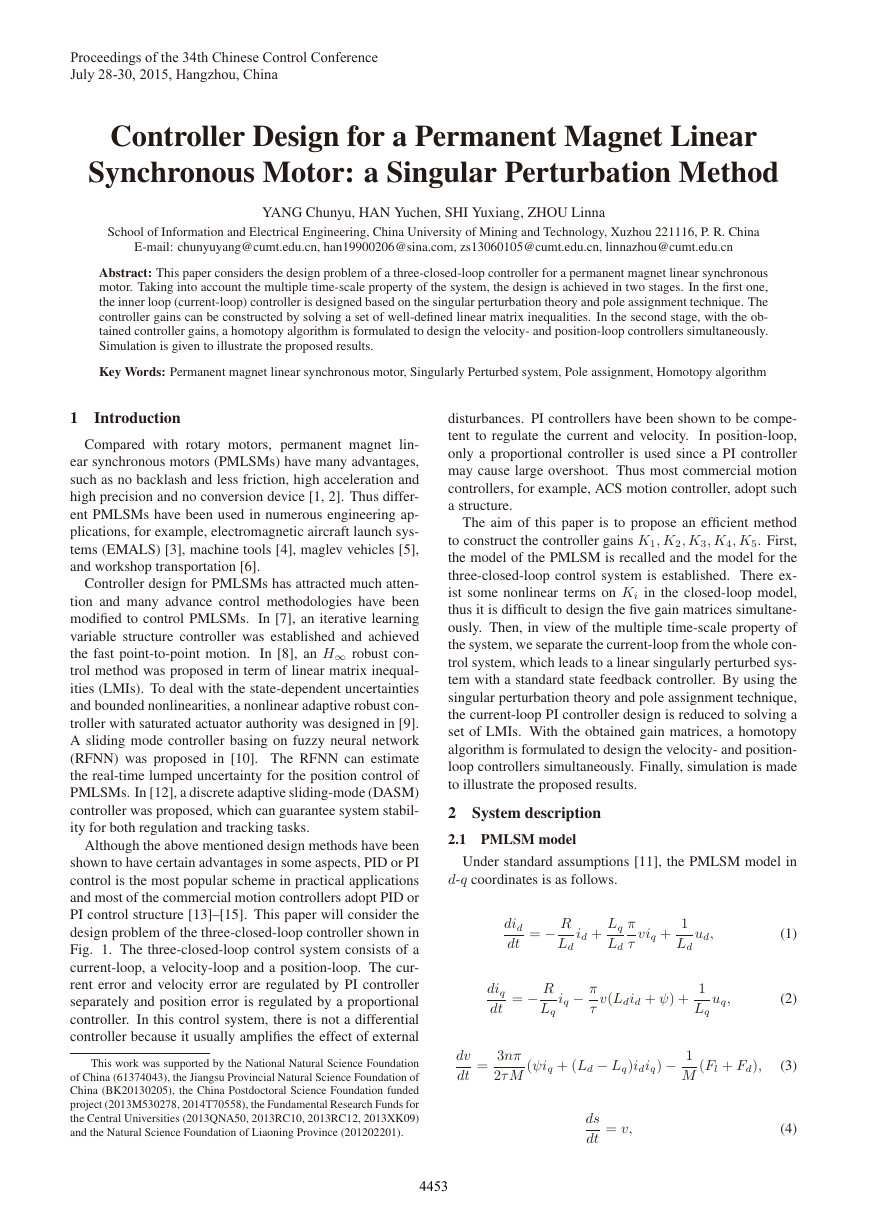
design problem of the three-closed-loop controller shown in
Fig. 1. The three-closed-loop control system consists of a
current-loop, a velocity-loop and a position-loop. The cur-
rent error and velocity error are regulated by PI controller
separately and position error is regulated by a proportional
controller. In this control system, there is not a differential
controller because it usually amplifies the effect of external
This work was supported by the National Natural Science Foundation
of China (61374043), the Jiangsu Provincial Natural Science Foundation of
China (BK20130205), the China Postdoctoral Science Foundation funded
project (2013M530278, 2014T70558), the Fundamental Research Funds for
the Central Universities (2013QNA50, 2013RC10, 2013RC12, 2013XK09)
and the Natural Science Foundation of Liaoning Province (201202201).
disturbances. PI controllers have been shown to be compe-
tent to regulate the current and velocity.
In position-loop,
only a proportional controller is used since a PI controller
may cause large overshoot. Thus most commercial motion
controllers, for example, ACS motion controller, adopt such
a structure.
The aim of this paper is to propose an efficient method
to construct the controller gains K1, K2, K3, K4, K5. First,
the model of the PMLSM is recalled and the model for the
three-closed-loop control system is established. There ex-
ist some nonlinear terms on Ki in the closed-loop model,
thus it is difficult to design the five gain matrices simultane-
ously. Then, in view of the multiple time-scale property of
the system, we separate the current-loop from the whole con-
trol system, which leads to a linear singularly perturbed sys-
tem with a standard state feedback controller. By using the
singular perturbation theory and pole assignment technique,
the current-loop PI controller design is reduced to solving a
set of LMIs. With the obtained gain matrices, a homotopy
algorithm is formulated to design the velocity- and position-
loop controllers simultaneously. Finally, simulation is made
to illustrate the proposed results.
2 System description
2.1 PMLSM model
Under standard assumptions [11], the PMLSM model in
d-q coordinates is as follows.
did
dt
= − R
Ld
id + Lq
Ld
π
τ
viq +
1
Ld
ud,
diq
dt
= − R
Lq
iq − π
τ
v(Ldid + ψ) +
1
Lq
uq,
(1)
(2)
=
dv
dt
3nπ
2τ M
(ψiq + (Ld − Lq)idiq) − 1
M
(Fl + Fd),
(3)
ds
dt
= v,
(4)
4453
�
Fig. 1: Three-closed-loop control system
where ud, uq and id, iq are the d-axis and q-axis voltages
and currents, respectively. Ld, Lq are the d-axis and q-axis
primary inductors, respectively. R, ψ, τ, v, s, n are the phase
winding resistance, winding inductance, pole pitch, linear
velocity, disturbance, the number of pole pairs, respectively.
Fl, Fd, M, B are the load force, edge effect force, mass of
the carrier, viscous friction coefficient, respectively.
In this paper, we assume that the d-axis and q-axis primary
inductors are equal, namely, Ld = Lq = L. Thus, (1)-(3)
can be written as
did
dt
diq
dt
dv
dt
= − R
L
= − R
L
3nπ
2τ M
=
1
viq +
L
vid − ψ
L
id + π
τ
iq − π
τ
ψiq − 1
M
(Fl + Fd).
ud,
v +
π
τ
1
L
uq,
(5)
(6)
(7)
Equations (5) and (6) show that the electrical dynamics id
and iq are coupled by nonlinear terms proportional to viq and
vid, which bring difficulties to controller design. There are
two strategies to alleviate this problem. One is based on the
introduction of a new control voltage absorbing nonlinear
term [11]. This paper will adopt another which is known
as id = 0 control strategy [16, 17].
In this strategy, the
actual line current id is assumed to be equal to its reference
∗
d = 0. Then we have a simplified model for
command i
PMLSMs
ds
dt
dv
dt
diq
dt
= v,
3nπψ
=
2τ M
= − R
L
iq − 1
M
iq − ψ
π
L
τ
(Fl + Fd),
v +
1
L
uq.
(8)
(9)
(10)
2.2 Closed-loop control system model
To construct closed-loop control system model, we intro-
∗ − v, ˙ηq = i
q − iq.
∗
∗ −
∗ − s, ev = v
According to Fig. 1, we have es = s
∗
∗ = K1es, i
∗
q = K2ev + K3ηv, u
q =
duce to new variables ˙ηv = v
q − iq, v
∗
v, eq = i
K4eq + K5ηq.
Then the dynamics of the closed-loop system is governed
4454
by the following equation
⎡
⎤
⎥⎥⎥⎥⎦ = (A0 + B0K0)
⎢⎢⎢⎢⎣
˙v
˙es
˙ηv
˙ηq
L˙iq
⎤
⎥⎥⎥⎥⎦ +
⎡
⎢⎢⎢⎢⎣
⎡
⎢⎢⎢⎢⎣
v
es
ηv
ηq
iq
− 1
M0
0
0
0
⎤
⎥⎥⎥⎥⎦ d0,
(11)
where
⎡
⎣
K0 =
⎡
⎢⎢⎢⎢⎣
⎡
⎢⎢⎢⎢⎣
A0 =
B0 =
⎤
⎥⎥⎥⎥⎦ ,
0
−1
−1
0
− πψ
τ
0 0 0
3πnψ
2τ M
0 0
0
0
0
0 0
0
0 0 0 −1
0 −R
0 0
⎤
⎥⎥⎥⎥⎦ , d0 = Fl + Fd,
0 0 0
0 0 0
1 0 0
0 1 0
0 0 1
K1
0
0
−K2
0
−K2K4 K1K2K4 K3K4 K5 −K4
0
K3
K1K2
0
0
⎤
⎦ .
It can be seen that K0 contains nonlinear terms on
K1, K2, K3, K4, K5. Thus it is difficult to calculate the con-
troller gains. To alleviate this issue, we decompose the de-
sign into two successive steps in view of the multi-time scale
property of the control system. We will first design current-
loop controller, then design position- and velocity-loop con-
trollers simultaneously.
To design the current-loop PI controller, we assume that
∗
q and the velocity are constant. Then
the current command i
according to Fig. 1 and equation (10), the dynamics of cur-
rent error eq is governed by the following equation
= (A1 + B1F )
d1,
(12)
˙ηq
L ˙eq
where
A1 =
0
1
0 −R
ηq
eq
0
−1
0
1
+
, d1 = Ri
.
, B1 =
F =
K5 K4
∗
q + πψ
τ
v,
�
With known K4, K5 and letting es = K1es, equation (11)
⎡
can be transformed into
⎡
⎤
⎤
⎤
⎥⎥⎥⎥⎦ = (A2 + B2G)
⎢⎢⎢⎢⎣
⎢⎢⎢⎢⎣
˙v
˙es
˙ηv
˙ηq
L˙iq
⎡
⎢⎢⎢⎢⎣
⎥⎥⎥⎥⎦ +
v
es
ηv
ηq
iq
⎥⎥⎥⎥⎦ d2,
− 1
M0
0
0
0
⎤
⎥⎥⎥⎥⎦ ,
where
⎡
⎢⎢⎢⎢⎣
A2 =
B2 =
G =
0 0
0 0
1 0
0 0
0 0 K5 −R − K4
3πnψ
2τ M
0
0
−1
τ
⎤
0
0
0
0
0
0
−1
0
− πψ
⎡
0
0
0 −1
0
0
1
0
0
K4
⎢⎢⎢⎢⎣
−K2 K2 K3
K1
0
0
⎥⎥⎥⎥⎦ , d2 = Fl + Fd,
.
0 0
0 0
Assume that d1 and d2 are constant. Then system (12) and
system (13) are linear time-invariant systems subject to con-
stant disturbances. If the closed-loop systems are designed
to be asymptotically stable, they have unique equilibrium
point. Specifically, the equilibrium point of (12) must sat-
isfy 0 = ˙ηq = eq and the equilibrium point of (13) should
satisfy 0 = ˙ηv = −v + ¯es and 0 = ˙¯es = −K1v, which
imply ¯es = 0, that is, es = 0. It can be seen that asymptotic
stability of the closed-loop systems guarantees the conver-
gence of the tracking errors eq and es, which is independent
of the disturbances. Therefore, the tracking PI controller de-
signs can be reduced to stabilization controller designs by
omitting the disturbances.
3 Controllers design
Taking into account the fact that L is very small, system
(12) and system (13) can be rewritten as the following sin-
gularly perturbed system.
E(ε) ˙x(t) = (A + BK)x(t) +Bd,
(14)
where E(ε) = diag{I, εI}, ε = L represents the singular
perturbation parameter.
According to the discussion in the previous section, the
tracking PI controller designs can be reduced to stabilization
controller designs by omitting the disturbances. Thus we
assume d = 0 in the sequel.
To enhance the performance of the control system, pole
constraints are considered in the controller design. To do
this, we recall the following definition and lemma.
DEFINITION 1 [19] A subset D of the complex plane C is
called an LMI region if there exist a symmetric matrix L ∈
Rd×d and a matrix M ∈ Rd×d such that
D = {z = x + jy ∈ C : fD(z) < 0},
(15)
where the characteristic function fD(z) is given as follows:
(16)
fD(z) = L + M z + M T z.
LEMMA 1 [19] Given a dynamic system ˙x(t) = Ax(t) and
an LMI region D, the system is D−stable, i.e., Λ(A) ∈ D
if there exists a matrix X ∈ Rn×n with X = X T > 0 such
that
(13)
L ⊗ X + M ⊗ (AX) +M T ⊗ (AX)T < 0,
where Λ(A) is the set of eigenvalues of A and ⊗ denotes the
Kronecker product of the matrices.
3.1 PI Controller for current-loop
According to equation (12), the PI Controller for current-
loop is a standard state feedback controller and can be de-
signed by the following theorem.
THEOREM 1 Given an LMI stability region D, if there exist
matrices Zk(k = 1, 2, 3) with Zk = Z T
k (k = 1, 2) and F
satisfying the following LMIs
Z1 > 0,
Z1 + εZ3
εZ3
εZ T
3
εZ2
> 0,
S1 < 0,
S1 + εS2 < 0,
where
V1 =
U1 =
Z1
0
0
0
0
Z1
Z3 Z2
, V2 =
, U2 =
0 Z T
3
Z3 Z2
0 Z T
3
0
0
(17)
(18)
(19)
(20)
,
,
S1 = L ⊗ V1 + M ⊗ (AU1) +M T ⊗ (AU1)T
+M ⊗ (B2F ) +M T ⊗ (B2F )T ,
S2 = L ⊗ V2 + M ⊗ (AU2) +M T ⊗ (AU2)T ,
and ⊗ denotes the Kronecker product of the matrices, then,
the poles of the closed-loop system with K = F (U1 +
εU2)−1 are all within the given LMI region D.
Proof: Assume that the LMIs in this theorem are feasible.
Then by simple calculation, we have
E(ε)Z(ε) = V1 + εV2,
and
S1 + εS2
= L ⊗ V1 + M ⊗ (AU1) +M T ⊗ (AU1)T
+M ⊗ (B2F ) +M T ⊗ (B2F )T
+ε(L ⊗ V2 + M ⊗ (AU2) +M T ⊗ (AU2)T )
= L ⊗ (V1 + εV2) +M ⊗ [A(U1 + εU2) +B 2F ]
+M T ⊗ [A(U1 + εU2) +B 2F ]T
= L ⊗ [E(ε)Z(ε)] + M ⊗ [(A + B2K(ε))Z(ε)]
+M T ⊗ [(A + B2K(ε))Z(ε)]T .
(21)
4455
�
Denote
FD = L ⊗ X(ε) +M ⊗ E
+M T ⊗ E
−1(ε)(A + B2K(ε))X(ε)
−1(ε) × (A + B2K(ε))X(ε)T , (22)
where X(ε) is a matrix with appropriate dimensions.
It is easy to show that
[I ⊗ E(ε)] × FD × [I ⊗ E(ε)]
= L ⊗ [E(ε)X(ε)E(ε)]
+M ⊗ [(A + B2K(ε))X(ε)E(ε)]
+M T ⊗ [E(ε)X(ε)(A + B2K(ε))T ].
(23)
Let X(ε) = Z(ε)E
−1(ε). LMIs (17), (18) imply that
E(ε)Z(ε) = Z T (ε)E(ε) > 0,
which shows
X(ε) = X T (ε) > 0.
Substituting X(ε) = Z(ε)E
−1(ε) into (23) gives
[I ⊗ E(ε)] × FD × [I ⊗ E(ε)]
= L ⊗ [E(ε)Z(ε)]
+M ⊗ [(A + B2K(ε))Z(ε)]
+M T ⊗ [Z T (ε)(A + B2K(ε))T ].
(24)
(25)
From (20), (23) and (25), it follows that
[I ⊗ E(ε)] × FD × [I ⊗ E(ε)] < 0,
which shows that
FD < 0.
(26)
By Lemma 1, inequalities (24) and (26) imply that the
poles of the closed-loop system with K = F (U1 + εU2)−1
are all within the given LMI region D. This completes the
proof.
REMARK 1 LMIs (17) and (19) seems redundant. But they
are significant to guarantee the whole LMI conditions in
Theorem 1 to be well-defined for any singular perturbation
parameter ε.
REMARK 2 Theorem 1 can be used directly to design PI
controller for the current-loop. And a suitable LMI region
D will leads to satisfactory control performance.
3.2 PI Controllers for velocity- and position-loop
It can seen from (13), the controllers for the velocity- and
position-loop are not a standard state feedback controllers
since the gain matrix is of specific structure, which make the
design complex.
By Theorem 1, we have the following theorem.
THEOREM 2 Given an LMI stability region D, if there exist
matrices G and Zk(k = 1, 2, 3) with Zk = Z T
k (k = 1, 2)
satisfying the following inequalities
Z1 > 0,
Z1 + εZ3
εZ3
εZ T
3
εZ2
> 0,
(27)
(28)
S1 < 0,
S1 + εS2 < 0,
(29)
(30)
,
,
0 Z T
3
Z3 Z2
0 Z T
3
0
0
where
V1 =
Z1
0
0
0
, V2 =
0
Z1
Z3 Z2
, U2 =
U1 =
S1 = L ⊗ V1 + M ⊗ [(A + BG)U1]
+M T ⊗ [(A + BG)U1]T ,
S2 = L ⊗ V2 + M ⊗ [(A + BG)U2]
+M T ⊗ [(A + BG)U2]T ,
then, the poles of the closed-loop system with K = G are all
within the given LMI region D.
To solve the inequalities (27)-(30), we first construct a
controller without this constraint by using Theorem 1, then
perform a homotopy algorithm to obtain the controller with
the specific structure
−K2 K2 K3
K1
0
0
.
0 0
0 0
G =
We rewrite the inequalities (27)-(30) into a compact form
F (G, Z1, Z1, Z3) < 0.
(31)
Following the line [20], we define the following matrix
function
L (G, Z1, Z2, Z3, λ)
= F ((1 − λ)G0 + λG, Z1, Z2, Z3),
(32)
where λ is a real number varying from 0 to 1, G0 is the full-
state-feedback gain which can be obtained by Theorem 1,
and G is the feedback gain with the specific structure. The
term (1− λ)G0 + λG in (32) defines a homotopy interpolat-
ing a full-state feedback controller and a desired state feed-
back controller, and our problem of finding a solution to (31)
is embedded in the family of problems
L (G, Z1, Z2, Z3, λ) < 0, λ ∈ [0, 1].
(33)
Now we are ready to formulate the homotopy algorithm.
Algorithm
Step 1 Solve the LMIs in Theorem 1 and obtain the full state
feedback gain G0, and matrices Z10, Z20, Z30. If the LMIs
are not feasible, this method fail to design a controller.
Step 2 Set k = 0, Gk = 0, and Z1k = Z10, Z2k =
Z20, Z3k = Z30.
Step 3 Set k = k + 1, λk = k/N. Compute a set so-
lutions Gk of L (G, Z1, Z2, Z3, λk) < 0, if it is feasible,
goto Step 4; if it is not feasible, compute a common solution
Z1k, Z2k, Z3k of L (Gk−1, Z1, Z2, Z3, λk) < 0, if it is fea-
sible, goto Step 4, if it is not feasible, set N = 2N and goto
Step 4.
Step 4 If N > Nmax, where Nmax is a prescribed upper
bound, then the algorithm ends without feasible solution,
else if k < Nmax, goto Step 3, and if k = N, the obtained
GN , Z1N , Z2N , Z3N are the feasible solutions.
4456
�
4 Simulation
In this section, the proposed methods are illustrated. The
parameters of the PMLSM are as follows: R = 4.7Ω, L =
1.5mH, τ = 0.015m, M = 2.2kg, n = 1, ψ = 0.4297wb.
Then the system matrices of (12) are as follows
Choose an LMI region D with
A1 =
, B1 =
L =
0
1
0 −4.7
−1000
−1 +sin 70◦
−cos70◦
0
0
−1
0
−110
,
cos70◦
1 +sin 70◦
.
,
,
M =
Solving the LMIs in Theorem 1 gives
K5 K4
=
9886.1 40.3
which serves as the current-loop controller gains.
⎤
Thus the system matrices of (13) are as follows
⎡
A2 =
⎢⎢⎢⎢⎣
0
0
0
0
−1
1
0
0
−90 0
⎡
0
0
0
0
0
⎥⎥⎥⎥⎦ ,
0
0
0
0
61
0
0
−1
9886.1 −44.7
⎤
0
0
0
1
40.3
Choose an LMI region D with
B2 =
L =
⎥⎥⎥⎥⎦ .
0
−1
0
0
0
⎢⎢⎢⎢⎣
−3000
,
−1 +sin 89◦
cos89◦
−cos89◦
1 +sin 89◦
−K2 K2 K3
−395 395 2813.4 0 0
0 0
0
0
0
−10
K1
0
0
0
144
0
0
0 0
,
M =
=
By using the homotopy algorithm with N = 100, we have
.
(34)
Now K1, K2, K3, K4 and K5 are all obtained. The sim-
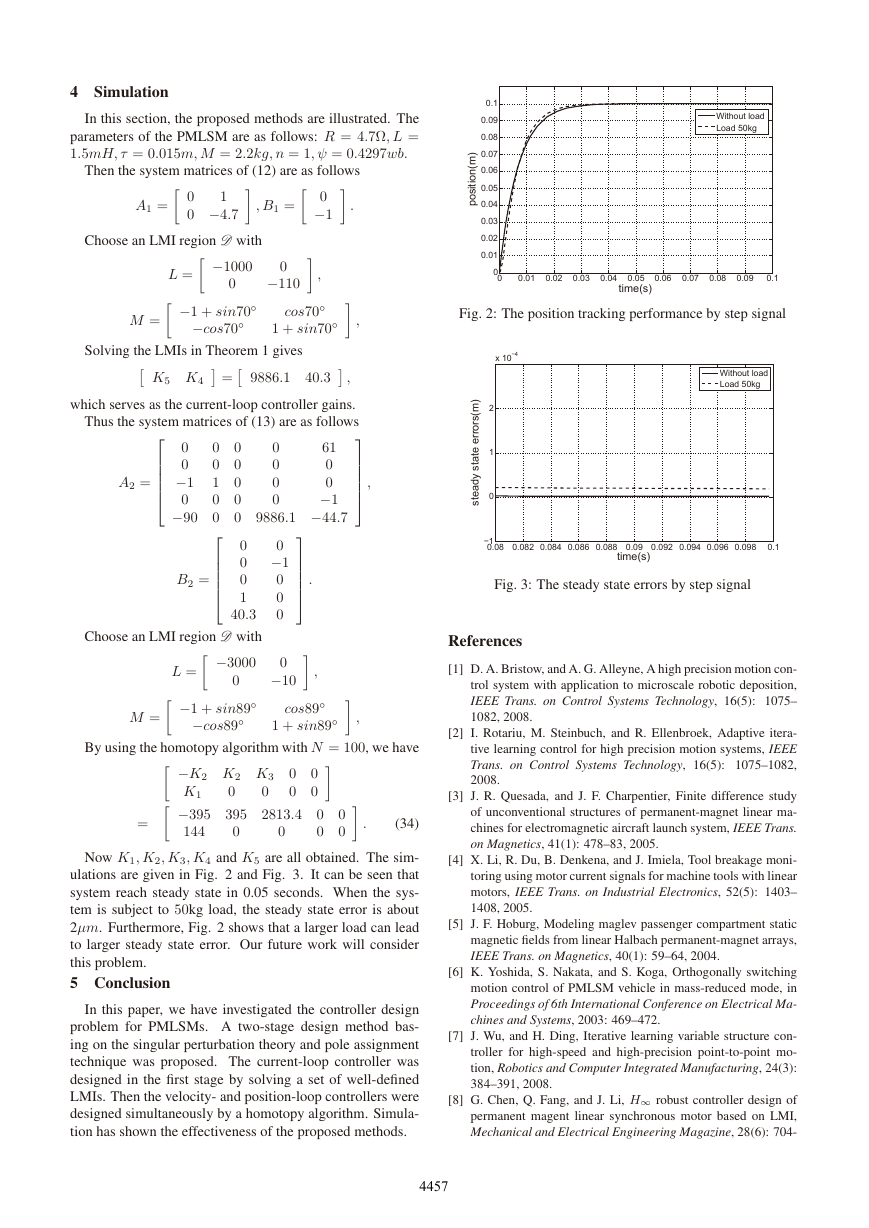
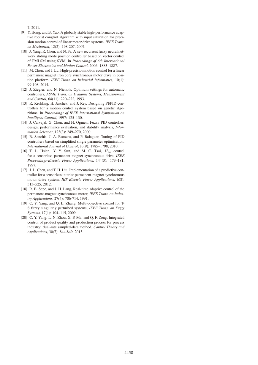
ulations are given in Fig. 2 and Fig. 3. It can be seen that
system reach steady state in 0.05 seconds. When the sys-
tem is subject to 50kg load, the steady state error is about
2μm. Furthermore, Fig. 2 shows that a larger load can lead
to larger steady state error. Our future work will consider
this problem.
5 Conclusion
In this paper, we have investigated the controller design
problem for PMLSMs. A two-stage design method bas-
ing on the singular perturbation theory and pole assignment
technique was proposed. The current-loop controller was
designed in the first stage by solving a set of well-defined
LMIs. Then the velocity- and position-loop controllers were
designed simultaneously by a homotopy algorithm. Simula-
tion has shown the effectiveness of the proposed methods.
Fig. 2: The position tracking performance by step signal
Fig. 3: The steady state errors by step signal
References
[1] D. A. Bristow, and A. G. Alleyne, A high precision motion con-
trol system with application to microscale robotic deposition,
IEEE Trans. on Control Systems Technology, 16(5): 1075–
1082, 2008.
[2] I. Rotariu, M. Steinbuch, and R. Ellenbroek, Adaptive itera-
tive learning control for high precision motion systems, IEEE
Trans. on Control Systems Technology, 16(5): 1075–1082,
2008.
[3] J. R. Quesada, and J. F. Charpentier, Finite difference study
of unconventional structures of permanent-magnet linear ma-
chines for electromagnetic aircraft launch system, IEEE Trans.
on Magnetics, 41(1): 478–83, 2005.
[4] X. Li, R. Du, B. Denkena, and J. Imiela, Tool breakage moni-
toring using motor current signals for machine tools with linear
motors, IEEE Trans. on Industrial Electronics, 52(5): 1403–
1408, 2005.
[5] J. F. Hoburg, Modeling maglev passenger compartment static
magnetic fields from linear Halbach permanent-magnet arrays,
IEEE Trans. on Magnetics, 40(1): 59–64, 2004.
[6] K. Yoshida, S. Nakata, and S. Koga, Orthogonally switching
motion control of PMLSM vehicle in mass-reduced mode, in
Proceedings of 6th International Conference on Electrical Ma-
chines and Systems, 2003: 469–472.
[7] J. Wu, and H. Ding, Iterative learning variable structure con-
troller for high-speed and high-precision point-to-point mo-
tion, Robotics and Computer Integrated Manufacturing, 24(3):
384–391, 2008.
[8] G. Chen, Q. Fang, and J. Li, H∞ robust controller design of
permanent magent linear synchronous motor based on LMI,
Mechanical and Electrical Engineering Magazine, 28(6): 704-
4457
�
7, 2011.
[9] Y. Hong, and B. Yao, A globally stable high-performance adap-
tive robust congtrol algorithm with input saturation for preci-
sion motion control of linear motor drive systems, IEEE Trans.
on Mechatron, 12(2): 198-207, 2007.
[10] J. Yang, R. Chen, and N. Fa, A new recurrent fuzzy neural net-
work sliding mode position controller based on vector control
of PMLSM using SVM, in Proceedings of 6th International
Power Electronics and Motion Control, 2006: 1883–1887.
[11] M. Chen, and J. Lu, High-precision motion control for a linear
permanent magnet iron core synchronous motor drive in posi-
tion platform, IEEE Trans. on Industrial Informatics, 10(1):
99-108, 2014.
[12] J. Ziegler, and N. Nichols, Optimum settings for automatic
controllers, ASME Trans. on Dynamic Systems, Measurement
and Control, 64(11): 220–222, 1993.
[13] R. Krohling, H. Jaschek, and J. Rey, Designing PI/PID con-
trollers for a motion control system based on genetic algo-
rithms, in Proceedings of IEEE International Symposium on
Intelligent Control, 1997: 125–130.
[14] J. Carvajal, G. Chen, and H. Ogmen, Fuzzy PID controller:
design, performance evaluation, and stability analysis, Infor-
mation Sciences, 123(3): 249–270, 2000.
[15] R. Sanchis, J. A. Romero, and P. Balaguer, Tuning of PID
controllers based on simplified single parameter optimisation,
International Journal of Control, 83(9): 1785–1798, 2010.
[16] T. L. Hsien, Y. Y. Sun, and M. C. Tsai, H∞ control
for a sensorless permanent-magnet synchronous drive, IEEE
Proceedings-Electric Power Applications, 144(3): 173–181,
1997.
[17] J. L. Chen, and T. H. Liu, Implementation of a predictive con-
troller for a sensorless interior permanent-magnet synchronous
motor drive system, IET Electric Power Applications, 6(8):
513–525, 2012.
[18] R. B. Sepe, and J. H. Lang, Real-time adaptive control of the
permanent-magnet synchronous motor, IEEE Trans. on Indus-
try Applications, 27(4): 706-714, 1991.
[19] C. Y. Yang, and Q. L. Zhang, Multi-objective control for T-
S fuzzy singularly perturbed systems, IEEE Trans. on Fuzzy
Systems, 17(1): 104–115, 2009.
[20] C. Y. Yang, L. N. Zhou, X. P. Ma, and Q. F. Zeng, Integrated
control of product quality and production process for process
industry: dual-rate sampled-data method, Control Theory and
Applications, 30(7): 844-849, 2013.
4458
�


 2023年江西萍乡中考道德与法治真题及答案.doc
 2012年重庆南川中考生物真题及答案.doc
 2013年江西师范大学地理学综合及文艺理论基础考研真题.doc
 2020年四川甘孜小升初语文真题及答案I卷.doc
 2020年注册岩土工程师专业基础考试真题及答案.doc
 2023-2024学年福建省厦门市九年级上学期数学月考试题及答案.doc
 2021-2022学年辽宁省沈阳市大东区九年级上学期语文期末试题及答案.doc
 2022-2023学年北京东城区初三第一学期物理期末试卷及答案.doc
 2018上半年江西教师资格初中地理学科知识与教学能力真题及答案.doc
 2012年河北国家公务员申论考试真题及答案-省级.doc
 2020-2021学年江苏省扬州市江都区邵樊片九年级上学期数学第一次质量检测试题及答案.doc
 2022下半年黑龙江教师资格证中学综合素质真题及答案.doc