元器件交易网www.cecb2b.com
Philips Semiconductors
N-channel TrenchMOS
transistor
Product specification
IRF640, IRF640S
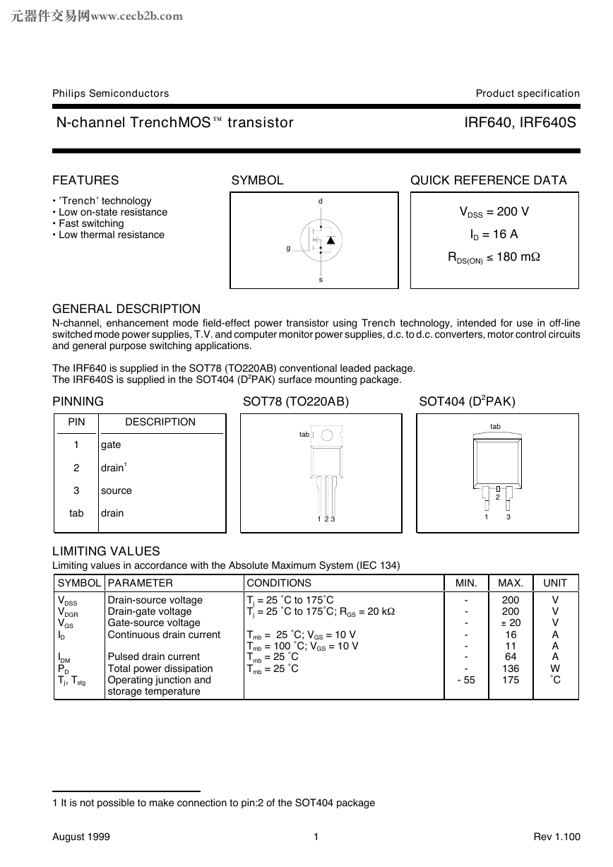
FEATURES
• ’Trench’ technology
• Low on-state resistance
• Fast switching
• Low thermal resistance
SYMBOL
QUICK REFERENCE DATA
d
s
g
VDSS = 200 V
ID = 16 A
RDS(ON) £ 180 mW
GENERAL DESCRIPTION
N-channel, enhancement mode field-effect power transistor using Trench technology, intended for use in off-line
switched mode power supplies, T.V. and computer monitor power supplies, d.c. to d.c. converters, motor control circuits
and general purpose switching applications.
The IRF640 is supplied in the SOT78 (TO220AB) conventional leaded package.
The IRF640S is supplied in the SOT404 (D2PAK) surface mounting package.
PINNING
SOT78 (TO220AB)
SOT404 (D2PAK)
PIN
DESCRIPTION
1
2
3
gate
drain1
source
tab
drain
tab
1 2 3
LIMITING VALUES
Limiting values in accordance with the Absolute Maximum System (IEC 134)
SYMBOL PARAMETER
VDSS
VDGR
VGS
ID
CONDITIONS
Tj = 25 ˚C to 175˚C
Tj = 25 ˚C to 175˚C; RGS = 20 kW
Tmb = 25 ˚C; VGS = 10 V
Tmb = 100 ˚C; VGS = 10 V
Tmb = 25 ˚C
Tmb = 25 ˚C
Drain-source voltage
Drain-gate voltage
Gate-source voltage
Continuous drain current
IDM
PD
Tj, Tstg
Pulsed drain current
Total power dissipation
Operating junction and
storage temperature
tab
2
1
3
MIN.
-
-
-
-
-
-
-
- 55
MAX.
200
200
– 20
16
11
64
136
175
UNIT
V
V
V
A
A
A
W
˚C
1 It is not possible to make connection to pin:2 of the SOT404 package
August 1999
1
Rev 1.100
�
元器件交易网www.cecb2b.com
Philips Semiconductors
N-channel TrenchMOS
transistor
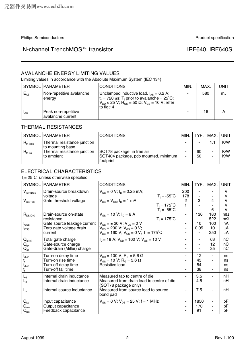
AVALANCHE ENERGY LIMITING VALUES
Limiting values in accordance with the Absolute Maximum System (IEC 134)
SYMBOL PARAMETER
EAS
Non-repetitive avalanche
energy
CONDITIONS
Unclamped inductive load, IAS = 6.2 A;
tp = 720 m s; Tj prior to avalanche = 25˚C;
VDD £ 25 V; RGS = 50 W
; VGS = 10 V; refer
to fig;14
IAS
Peak non-repetitive
avalanche current
THERMAL RESISTANCES
SYMBOL PARAMETER
Rth j-mb
CONDITIONS
Rth j-a
Thermal resistance junction
to mounting base
Thermal resistance junction SOT78 package, in free air
to ambient
SOT404 package, pcb mounted, minimum
footprint
ELECTRICAL CHARACTERISTICS
Tj= 25˚C unless otherwise specified
SYMBOL PARAMETER
V(BR)DSS
Drain-source breakdown
voltage
Gate threshold voltage
CONDITIONS
VGS = 0 V; ID = 0.25 mA;
VDS = VGS; ID = 1 mA
Tj = -55˚C
Tj = 175˚C
Tj = -55˚C
Tj = 175˚C
VGS(TO)
RDS(ON)
IGSS
IDSS
Qg(tot)
Qgs
Qgd
td on
tr
td off
tf
Ld
Ld
Ls
Ciss
Coss
Crss
VGS = 10 V; ID = 8 A
Drain-source on-state
resistance
Gate source leakage current VGS = – 20 V; VDS = 0 V
VDS = 200 V; VGS = 0 V;
Zero gate voltage drain
VDS = 160 V; VGS = 0 V; Tj = 175˚C
current
Total gate charge
ID = 18 A; VDD = 160 V; VGS = 10 V
Gate-source charge
Gate-drain (Miller) charge
Turn-on delay time
Turn-on rise time
Turn-off delay time
Turn-off fall time
Internal drain inductance
Internal drain inductance
VDD = 100 V; RD = 5.6 W
VGS = 10 V; RG = 5.6 W
Resistive load
;
Measured tab to centre of die
Measured from drain lead to centre of die
(SOT78 package only)
Measured from source lead to source
bond pad
VGS = 0 V; VDS = 25 V; f = 1 MHz
Internal source inductance
Input capacitance
Output capacitance
Feedback capacitance
Product specification
IRF640, IRF640S
MIN.
-
-
MAX.
580
UNIT
mJ
16
A
MIN. TYP. MAX. UNIT
K/W
1.1
-
-
-
-
60
50
-
-
K/W
K/W
130
-
-
3
-
-
10
0.05
MIN. TYP. MAX. UNIT
200
178
2
1
-
-
-
-
-
-
-
-
-
-
-
-
-
-
-
V
-
V
-
V
4
-
V
6
V
180 mW
522 mW
nA
100
m A
10
m A
250
63
nC
nC
12
nC
35
ns
-
-
ns
ns
-
ns
-
nH
-
-
nH
-
-
-
-
12
45
54
38
3.5
4.5
-
-
-
-
7.5
1850
170
91
-
-
-
-
nH
pF
pF
pF
August 1999
2
Rev 1.100
�
元器件交易网www.cecb2b.com
Philips Semiconductors
N-channel TrenchMOS
transistor
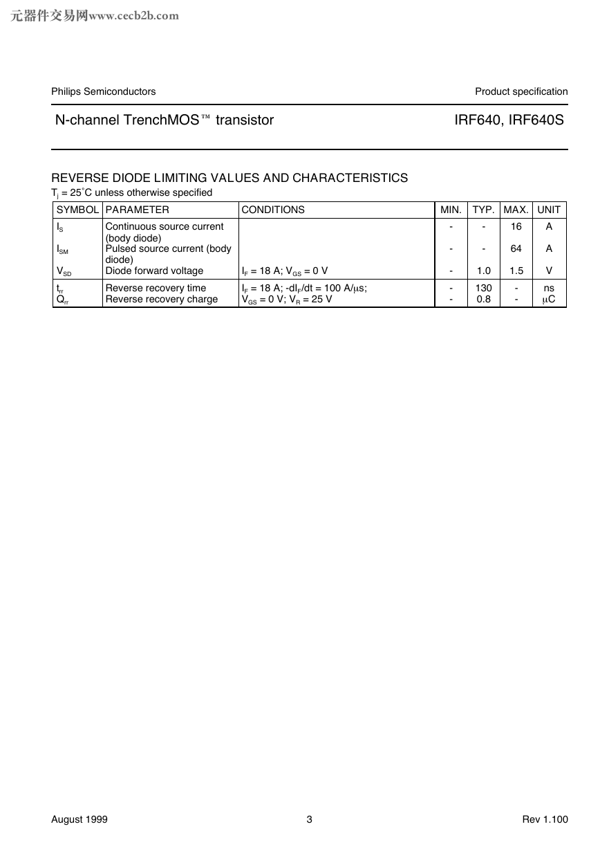
REVERSE DIODE LIMITING VALUES AND CHARACTERISTICS
Tj = 25˚C unless otherwise specified
SYMBOL PARAMETER
IS
CONDITIONS
IF = 18 A; VGS = 0 V
IF = 18 A; -dIF/dt = 100 A/m s;
VGS = 0 V; VR = 25 V
Continuous source current
(body diode)
Pulsed source current (body
diode)
Diode forward voltage
Reverse recovery time
Reverse recovery charge
ISM
VSD
trr
Qrr
Product specification
IRF640, IRF640S
MIN. TYP. MAX. UNIT
-
-
-
-
-
-
-
1.0
130
0.8
16
64
1.5
-
-
A
A
V
ns
m C
August 1999
3
Rev 1.100
�
元器件交易网www.cecb2b.com
Philips Semiconductors
N-channel TrenchMOS
transistor
Product specification
IRF640, IRF640S
100
90
80
70
60
50
40
30
20
10
0
100
90
80
70
60
50
40
30
20
10
0
Normalised Power Derating, PD (%)
Transient thermal impedance, Zth j-mb (K/W)
10
1
D = 0.5
0.1
0.2
0.1
0.05
0.02
0.01
single pulse
0.001
P
D
tp D = tp/T
T
150
175
1E-06
1E-05
1E-04
1E-03
1E-02
1E-01
1E+00
Pulse width, tp (s)
0
25
50
75
100
125
Mounting Base temperature, Tmb (C)
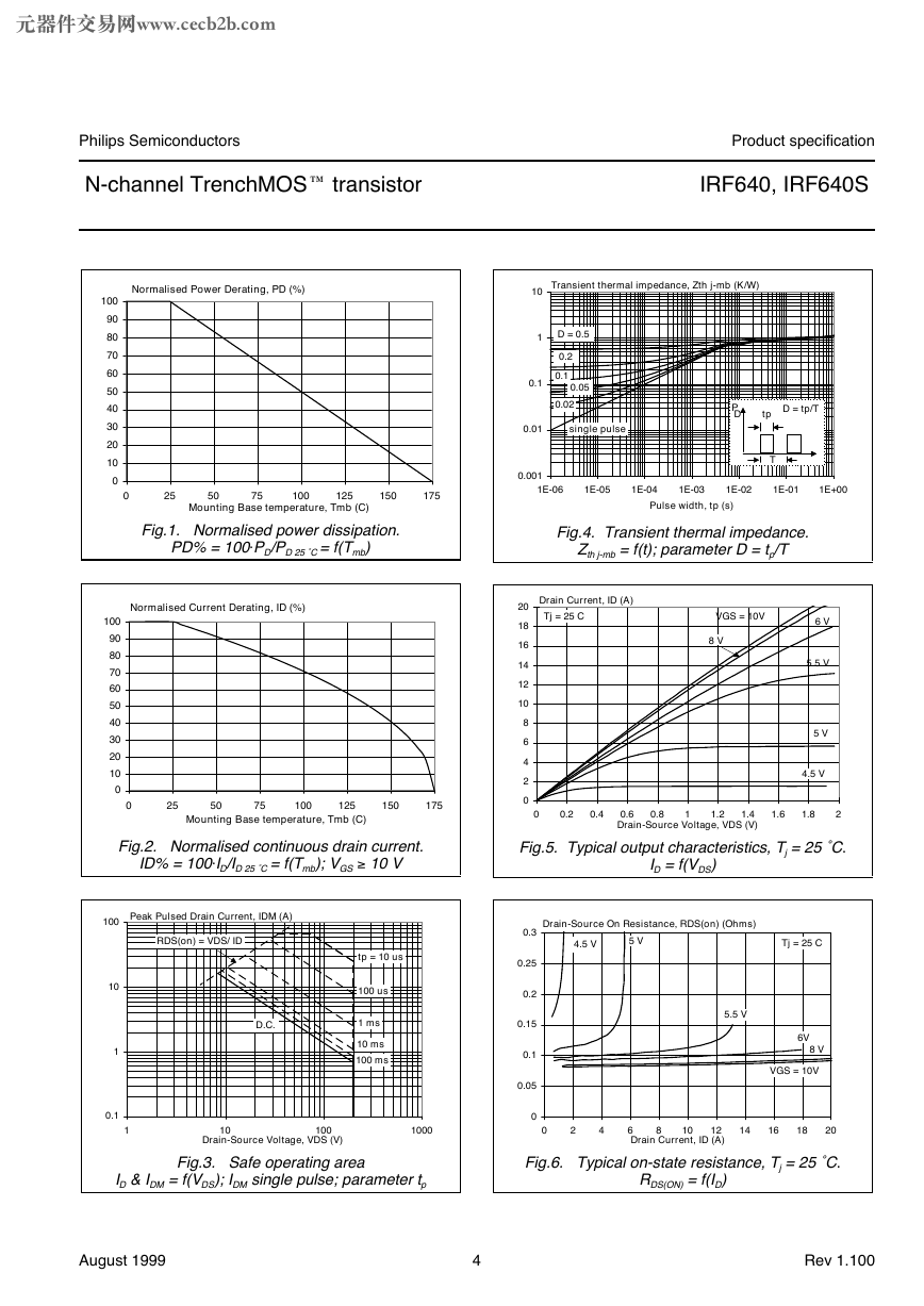
Fig.1. Normalised power dissipation.
PD% = 100 PD/PD 25 ˚C = f(Tmb)
Fig.4. Transient thermal impedance.
Zth j-mb = f(t); parameter D = tp/T
Normalised Current Derating, ID (%)
0
25
50
75
100
125
150
175
Mounting Base temperature, Tmb (C)
Drain Current, ID (A)
Tj = 25 C
VGS = 10V
8 V
20
18
16
14
12
10
8
6
4
2
0
0
0.2
0.4
0.6
1.4
Drain-Source Voltage, VDS (V)
0.8
1.2
1
6 V
5.5 V
5 V
4.5 V
1.6
1.8
2
Fig.2. Normalised continuous drain current.
ID% = 100 ID/ID 25 ˚C = f(Tmb); VGS ‡ 10 V
Fig.5. Typical output characteristics, Tj = 25 ˚C.
ID = f(VDS)
Peak Pulsed Drain Current, IDM (A)
100
RDS(on) = VDS/ ID
10
1
0.1
1
tp = 10 us
100 us
1 ms
10 ms
100 ms
D.C.
10
100
Drain-Source Voltage, VDS (V)
Drain-Source On Resistance, RDS(on) (Ohms)
4.5 V
5 V
Tj = 25 C
5.5 V
6V
8 V
VGS = 10V
0.3
0.25
0.2
0.15
0.1
0.05
0
1000
0
2
4
6
12
Drain Current, ID (A)
10
8
14
16
18
20
Fig.3. Safe operating area
ID & IDM = f(VDS); IDM single pulse; parameter tp
Fig.6. Typical on-state resistance, Tj = 25 ˚C.
RDS(ON) = f(ID)
August 1999
4
Rev 1.100
�
元器件交易网www.cecb2b.com
Philips Semiconductors
N-channel TrenchMOS
transistor
Product specification
IRF640, IRF640S
20
18
16
14
12
10
8
6
4
2
0
25
20
15
10
5
0
Drain current, ID (A)
VDS > ID X RDS(ON)
Threshold Voltage, VGS(TO) (V)
maximum
typical
minimum
4.5
4
3.5
3
2.5
2
1.5
1
0.5
0
175 C
Tj = 25 C
0
1
2
3
4
5
6
-60 -40 -20
0
20
40
60
80 100 120 140 160 180
Gate-source voltage, VGS (V)
Junction Temperature, Tj (C)
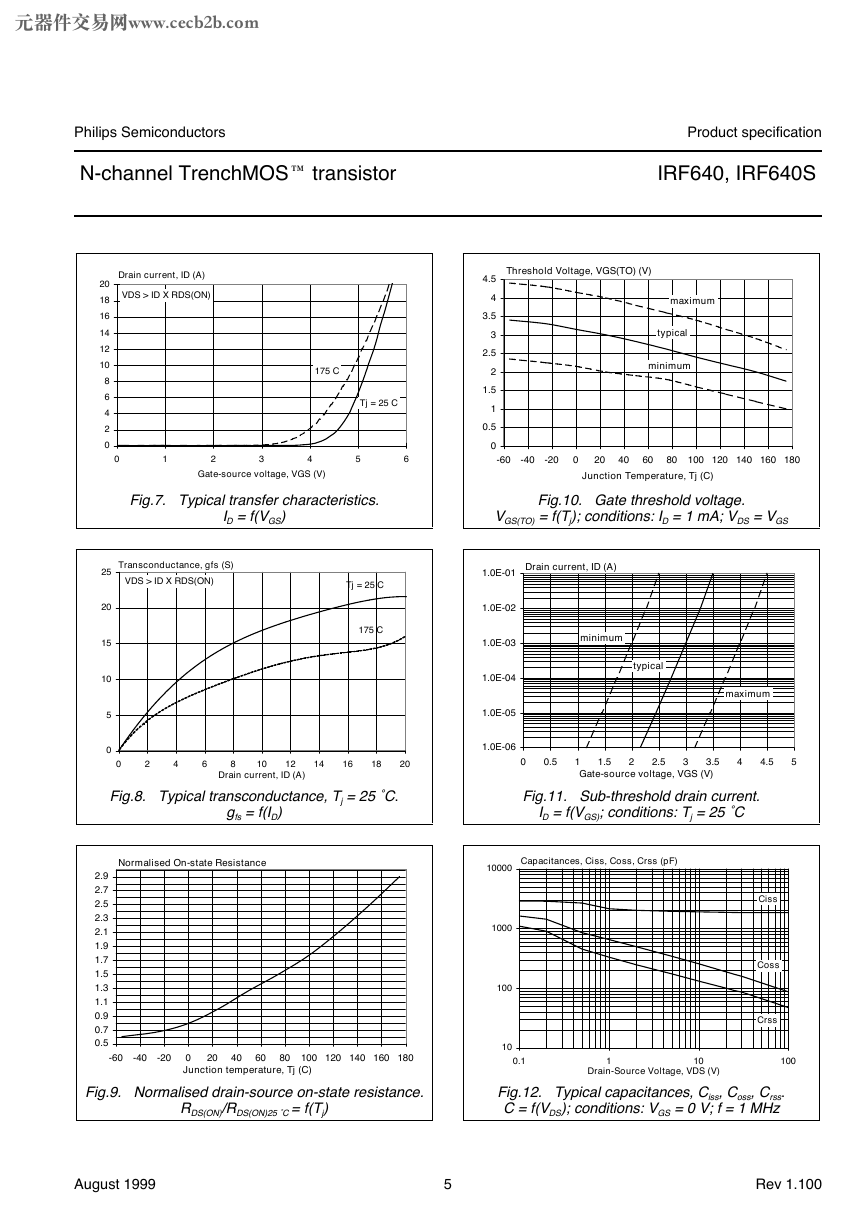
Fig.7. Typical transfer characteristics.
ID = f(VGS)
Fig.10. Gate threshold voltage.
VGS(TO) = f(Tj); conditions: ID = 1 mA; VDS = VGS
Transconductance, gfs (S)
VDS > ID X RDS(ON)
Tj = 25 C
175 C
Drain current, ID (A)
minimum
typical
1.0E-01
1.0E-02
1.0E-03
1.0E-04
1.0E-05
1.0E-06
0
2
4
6
8
10
12
Drain current, ID (A)
14
16
18
20
0
0.5
1.5
1
Gate-source voltage, VGS (V)
2.5
2
3
3.5
maximum
4
4.5
5
Fig.8. Typical transconductance, Tj = 25 ˚C.
gfs = f(ID)
Fig.11. Sub-threshold drain current.
ID = f(VGS); conditions: Tj = 25 ˚C
Normalised On-state Resistance
2.9
2.7
2.5
2.3
2.1
1.9
1.7
1.5
1.3
1.1
0.9
0.7
0.5
-60 -40 -20
20
0
Junction temperature, Tj (C)
40
60
80 100 120 140 160 180
10
0.1
1
10
Drain-Source Voltage, VDS (V)
Fig.9. Normalised drain-source on-state resistance.
RDS(ON)/RDS(ON)25 ˚C = f(Tj)
Fig.12. Typical capacitances, Ciss, Coss, Crss.
C = f(VDS); conditions: VGS = 0 V; f = 1 MHz
August 1999
5
Rev 1.100
Capacitances, Ciss, Coss, Crss (pF)
10000
1000
100
Ciss
Coss
Crss
100
�
元器件交易网www.cecb2b.com
Philips Semiconductors
N-channel TrenchMOS
transistor
Product specification
IRF640, IRF640S
Source-Drain Diode Current, IF (A)
VGS = 0 V
175 C
Tj = 25 C
20
18
16
14
12
10
8
6
4
2
0
0
0.1
0.2
0.3
0.4
0.5
0.6
0.7
0.8
0.9
1
1.1
1.2
Source-Drain Voltage, VSDS (V)
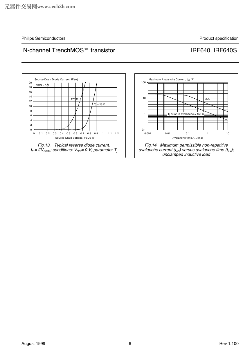
Fig.13. Typical reverse diode current.
IF = f(VSDS); conditions: VGS = 0 V; parameter Tj
Maximum Avalanche Current, IAS (A)
25 C
Tj prior to avalanche = 150 C
100
10
1
0.1
0.001
0.01
0.1
1
10
Avalanche time, tAV (ms)
Fig.14. Maximum permissible non-repetitive
avalanche current (IAS) versus avalanche time (tAV);
unclamped inductive load
August 1999
6
Rev 1.100
�
元器件交易网www.cecb2b.com
Philips Semiconductors
N-channel TrenchMOS
transistor
MECHANICAL DATA
Product specification
IRF640, IRF640S
Plastic single-ended package; heatsink mounted; 1 mounting hole; 3-lead TO-220
SOT78
E
P
A
A1
q
L1
D1
(1)
L2
b1
D
L
1
2
3
b
e
e
0
5
10 mm
scale
Q
c
DIMENSIONS (mm are the original dimensions)
UNIT
mm
A
4.5
4.1
A1
1.39
1.27
b
0.9
0.7
b1
1.3
1.0
c
0.7
0.4
D
15.8
15.2
D1
6.4
5.9
E
e
L
10.3
9.7
2.54
15.0
13.5
(1)
L2
max.
3.0
L1
3.30
2.79
P
3.8
3.6
q
3.0
2.7
Q
2.6
2.2
Note
1. Terminals in this zone are not tinned.
OUTLINE
VERSION
SOT78
REFERENCES
IEC
JEDEC
TO-220
EIAJ
EUROPEAN
PROJECTION
ISSUE DATE
97-06-11
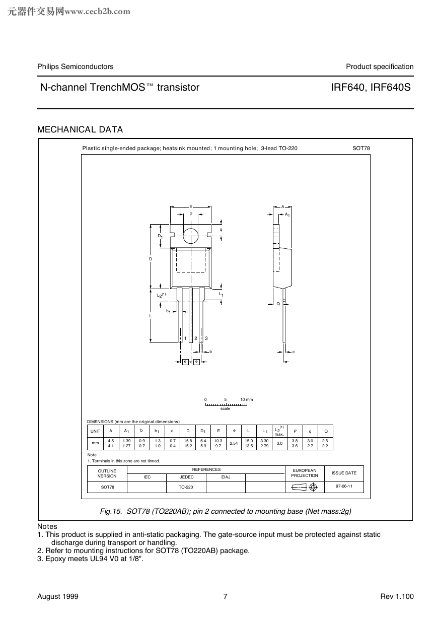
Fig.15. SOT78 (TO220AB); pin 2 connected to mounting base (Net mass:2g)
Notes
1. This product is supplied in anti-static packaging. The gate-source input must be protected against static
discharge during transport or handling.
2. Refer to mounting instructions for SOT78 (TO220AB) package.
3. Epoxy meets UL94 V0 at 1/8".
August 1999
7
Rev 1.100
�
元器件交易网www.cecb2b.com
Philips Semiconductors
N-channel TrenchMOS
transistor
MECHANICAL DATA
Product specification
IRF640, IRF640S
Plastic single-ended surface mounted package (Philips version of D2-PAK); 3 leads
(one lead cropped)
SOT404
A
A1
mounting
base
D1
D
HD
E
2
1
e
e
3
b
Lp
c
Q
0
2.5
5 mm
scale
DIMENSIONS (mm are the original dimensions)
UNIT
A
mm
4.50
4.10
A1
1.40
1.27
b
0.85
0.60
c
0.64
0.46
D
max.
11
D1
1.60
1.20
E
e
10.30
9.70
2.54
Lp
2.90
2.10
HD
Q
15.40
14.80
2.60
2.20
OUTLINE
VERSION
SOT404
IEC
JEDEC
EIAJ
REFERENCES
EUROPEAN
PROJECTION
ISSUE DATE
98-12-14
99-06-25
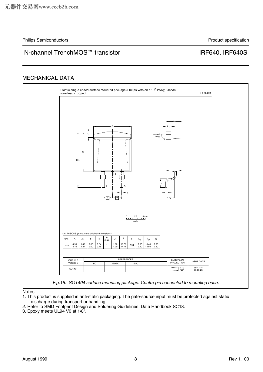
Fig.16. SOT404 surface mounting package. Centre pin connected to mounting base.
Notes
1. This product is supplied in anti-static packaging. The gate-source input must be protected against static
discharge during transport or handling.
2. Refer to SMD Footprint Design and Soldering Guidelines, Data Handbook SC18.
3. Epoxy meets UL94 V0 at 1/8".
August 1999
8
Rev 1.100
�


 2023年江西萍乡中考道德与法治真题及答案.doc
 2012年重庆南川中考生物真题及答案.doc
 2013年江西师范大学地理学综合及文艺理论基础考研真题.doc
 2020年四川甘孜小升初语文真题及答案I卷.doc
 2020年注册岩土工程师专业基础考试真题及答案.doc
 2023-2024学年福建省厦门市九年级上学期数学月考试题及答案.doc
 2021-2022学年辽宁省沈阳市大东区九年级上学期语文期末试题及答案.doc
 2022-2023学年北京东城区初三第一学期物理期末试卷及答案.doc
 2018上半年江西教师资格初中地理学科知识与教学能力真题及答案.doc
 2012年河北国家公务员申论考试真题及答案-省级.doc
 2020-2021学年江苏省扬州市江都区邵樊片九年级上学期数学第一次质量检测试题及答案.doc
 2022下半年黑龙江教师资格证中学综合素质真题及答案.doc