logo资料库

PEF-7071-V-V1.5-Lantiq-datasheet-62314344.pdf

第1页 / 共188页
第2页 / 共188页
第3页 / 共188页
第4页 / 共188页
第5页 / 共188页
第6页 / 共188页
第7页 / 共188页
第8页 / 共188页
资料共188页,剩余部分请下载后查看
Table of Contents
List of Figures
List of Tables
1 Introduction
1.1 About XWAY™ PHY11G
1.2 Overview
1.2.1 Logic Symbol
1.2.2 Features
1.2.3 Typical Applications
1.2.3.1 Copper Application
1.2.3.2 Media Converter Application
1.2.3.3 Gigabit Interface Converter (GBIC) Application
1.2.4 Terminology and Nomenclature
2 External Signals
2.1 Pin Diagram
2.2 Pin Description
2.2.1 Pin Identifications
2.2.2 General Pins
2.2.3 Media-Dependent Interface (MDI) Pins
2.2.4 Media-Independent Interface (MII) Pins
2.2.5 Control Interface Pins
2.2.6 JTAG Interface
2.2.7 Power Supply Pins
3 Functional Description
3.1 Modes of Operation
3.1.1 Copper Flow
3.1.2 Media Converter Flow
3.2 Media-Independent Interfaces (MII)
3.2.1 X-speed Media-Independent Interface (xMII)
3.2.1.1 xMII Signal Multiplexing
3.2.1.2 xMII Signal Conditioning
3.2.2 Reduced Media-Independent Interface (RMII)
3.2.3 Reduced Gigabit Media-Independent Interface (RGMII)
3.2.4 Serial Gigabit Media-Independent Interface (SGMII)
3.2.5 Reduced Ten Bit Interface (RTBI)
3.3 Media Functions
3.3.1 Media-Dependent Interfaces (MDI)
3.3.1.1 Copper Interface
3.3.1.2 Fiber Interface
3.3.2 Auto-Negotiation
3.3.3 Auto-Downspeed
3.3.4 Auto-Crossover and Polarity-Reversal Correction
3.3.5 Transformerless Ethernet (TLE)
3.4 Configuration, Control and Status Functions
3.4.1 Configuration of XWAY™ PHY11G via Pin-Strapping
3.4.2 Configuration of XWAY™ PHY11G via External EEPROM
3.4.2.1 EEPROM Applications
3.4.2.2 EEPROM Detection
3.4.2.3 EEPROM Content
3.4.2.4 EEPROM Frame Formats
3.4.3 Configuration and Control Via MDIO
3.4.3.1 MDIO Interface
3.4.3.2 MDIO Address Space
3.4.3.3 MDIO Interrupt
3.4.4 LED Interface
3.4.4.1 Single Color LED Mode
3.4.4.2 Bi-Color LED Mode
3.4.4.3 LED Operations
3.5 Power Management
3.5.1 Power Supply
3.5.1.1 Power Supply Using Integrated Switching Regulator
3.5.1.2 Power Supply Without Using Integrated Switching Regulator
3.5.2 Power Over Ethernet (PoE)
3.5.2.1 Powered Device (PD)
3.5.2.2 Power Sourcing Equipment (PSE)
3.5.3 Energy-Efficient Ethernet
3.5.3.1 EEE for 10BASE-Te
3.5.3.2 EEE for 100BASE-TX
3.5.3.3 EEE for 1000BASE-T
3.5.3.4 Auto-Negotiation for EEE Modes
3.5.3.5 Support of Legacy MACs
3.5.4 Wake-on-LAN (WoL)
3.5.5 Power Down Modes
3.5.5.1 PD_FORCE Mode
3.5.5.2 ANEG Mode
3.5.5.3 PD_IDLE Mode
3.5.5.4 DATA Mode
3.5.5.5 EEE Mode
3.6 Testing Functions
3.6.1 JTAG Interface
3.6.2 Payload Data Tests
3.6.2.1 Test Packet Generator (TPG)
3.6.2.2 Error Counters
3.6.3 Test Loops
3.6.3.1 Near-End Test Loops
3.6.3.2 Far-End Test Loop
4 MDIO Registers
4.1 STD: Standard Management Registers
4.2 PHY: PHY-Specific Management Registers
5 MMD Registers
5.1 EEE: Standard EEE Registers for MMD=0x03
5.2 ANEG: Standard Auto-Negotiation Registers for MMD=0x07
5.3 EEPROM: EEPROM Address Space (MMD=0x1E)
5.4 INTERNAL: Internal Address Space (MMD=0x1F)
6 Electrical Characteristics
6.1 Absolute Maximum Ratings
6.2 Operating Range
6.3 Recommended Operating Conditions
6.4 Power-Up Sequence
6.5 DC Characteristics
6.5.1 Digital Interfaces
6.5.1.1 GPIO Interfaces
6.5.1.2 MII Receive Interface
6.5.1.3 MII Transmit Interface
6.5.1.4 LED Interface
6.5.1.5 JTAG Interface
6.5.2 Twisted-Pair Interface
6.5.3 SGMII Interface
6.5.4 1000BASE-X Interface
6.6 AC Characteristics
6.6.1 Reset
6.6.2 Power Supply
6.6.3 Input Clock
6.6.4 Output Clock
6.6.5 MDIO Interface
6.6.6 RMII Interface
6.6.7 RGMII Interface
6.6.7.1 Transmit Timing Characteristics
6.6.7.2 Receive Timing Characteristics
6.6.8 RTBI Interface
6.6.8.1 Transmit Timing Characteristics
6.6.8.2 Receive Timing Characteristics
6.6.9 SGMII Interface
6.6.9.1 Transmit Timing Characteristics
6.6.9.2 Receive Timing Characteristics
6.6.10 1000BASE-X Interface
6.6.10.1 Transmit Timing Characteristics
6.6.10.2 Receive Timing Characteristics
6.6.11 Twisted-Pair Interface
6.7 Isolation Requirements
6.8 External Circuitry
6.8.1 Crystal
6.8.2 LED
6.8.3 Transformer (Magnetics)
6.8.4 RJ45 Plug
6.8.5 Twisted-Pair Common-Mode Rejection and Termination Circuitry
6.8.6 SGMII Interface
6.8.7 1000BASE-X Interface
7 Package Outline
References
Terminology
XWAY™ PHY Ethernet Physical Layer Devices XWAY™ PHY11G Single Port Gigabit Ethernet PHY (10/100/1000 Mbit/s) PEF 7071, Version 1.5 User’s Manual Hardware Description Revision 1.0, 2012-02-17
Edition 2012-02-17 Published by Lantiq Deutschland GmbH Am Campeon 3 85579 Neubiberg, Germany © 2012 Lantiq Deutschland GmbH All Rights Reserved. Legal Disclaimer The information given in this document shall in no event be regarded as a guarantee of conditions or characteristics. With respect to any examples or hints given herein, any typical values stated herein and/or any information regarding the application of the device, Lantiq hereby disclaims any and all warranties and liabilities of any kind, including without limitation, warranties of non-infringement of intellectual property rights of any third party. Information For further information on technology, delivery terms and conditions and prices, please contact the nearest Lantiq Office (www.lantiq.com). Warnings Due to technical requirements, components may contain dangerous substances. For information on the types in question, please contact the nearest Lantiq Office. Lantiq components may be used in life-support devices or systems only with the express written approval of Lantiq, if a failure of such components can reasonably be expected to cause the failure of that life-support device or system or to affect the safety or effectiveness of that device or system. Life support devices or systems are intended to be implanted in the human body or to support and/or maintain and sustain and/or protect human life. If they fail, it is reasonable to assume that the health of the user or other persons may be endangered.
XWAY™ PHY11G (PEF 7071) Single Port Gigabit Ethernet PHY (10/100/1000 Mbit/s) XWAY™ PHY11G, Single Port Gigabit Ethernet PHY (10/100/1000 Mbit/s) Revision History: 2012-02-17, Revision 1.0 Previous Revision: none Page Subjects (major changes since last revision) Trademarks of Lantiq CONVERGATE™, COSIC™, DUALFALC™, DUSLIC™, ELIC™, EPIC™, FALC™, GEMINAX™, ISAC™, IWORX™, OCTALFALC™, OCTAT™, QUADFALC™, SCOUT™, SEROCCO™, SICOFI™, SLIC™, SMINT™, SOCRATES™, VINAX™, VINETIC™, XWAY™ Other Trademarks ARM™, Bluetooth™ of Bluetooth SIG Inc. CAT-iq™ of DECT Forum. EPCOS™ of Epcos AG. HYPERTERMINAL™ of Hilgraeve Incorporated. IEC™ of Commission Electrotechnique Internationale. IrDA™ of Infrared Data Association Corporation. ISO™ of INTERNATIONAL ORGANIZATION FOR STANDARDIZATION. MATLAB™ of MathWorks, Inc. NUCLEUS™ of Mentor Graphics Corporation. MIPS® of MIPS Technologies, Inc., USA. muRata™ of MURATA MANUFACTURING CO. SOLARIS™ of Sun Microsystems, Inc. Samtec® of Samtec Inc. TEAKLITE™ of CEVA, Inc. TEKTRONIX™ of Tektronix Inc. UNIX™ of X/Open Company Limited. VERILOG™, PALLADIUM™ of Cadence Design Systems, Inc. VxWorks™, WIND RIVER™ of WIND RIVER SYSTEMS. Last Trademarks Update 2012-01-04 User’s Manual Hardware Description 3 Revision 1.0, 2012-02-17
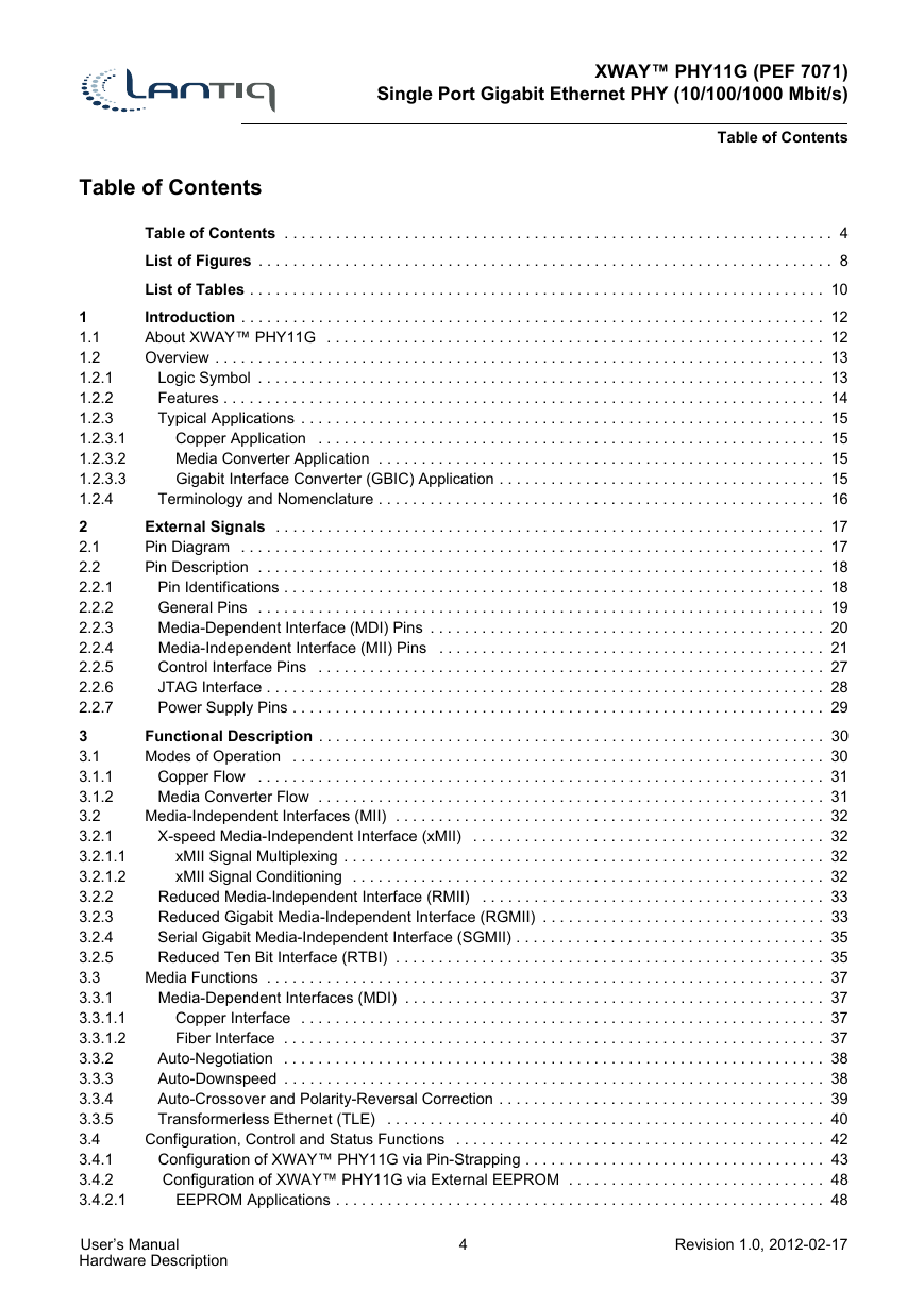
XWAY™ PHY11G (PEF 7071) Single Port Gigabit Ethernet PHY (10/100/1000 Mbit/s) Table of Contents Table of Contents Table of Contents . . . . . . . . . . . . . . . . . . . . . . . . . . . . . . . . . . . . . . . . . . . . . . . . . . . . . . . . . . . . . . . . 4 List of Figures . . . . . . . . . . . . . . . . . . . . . . . . . . . . . . . . . . . . . . . . . . . . . . . . . . . . . . . . . . . . . . . . . . . 8 List of Tables . . . . . . . . . . . . . . . . . . . . . . . . . . . . . . . . . . . . . . . . . . . . . . . . . . . . . . . . . . . . . . . . . . . 10 Introduction . . . . . . . . . . . . . . . . . . . . . . . . . . . . . . . . . . . . . . . . . . . . . . . . . . . . . . . . . . . . . . . . . . . . 12 About XWAY™ PHY11G . . . . . . . . . . . . . . . . . . . . . . . . . . . . . . . . . . . . . . . . . . . . . . . . . . . . . . . . . . 12 Overview . . . . . . . . . . . . . . . . . . . . . . . . . . . . . . . . . . . . . . . . . . . . . . . . . . . . . . . . . . . . . . . . . . . . . . . 13 Logic Symbol . . . . . . . . . . . . . . . . . . . . . . . . . . . . . . . . . . . . . . . . . . . . . . . . . . . . . . . . . . . . . . . . . . 13 Features . . . . . . . . . . . . . . . . . . . . . . . . . . . . . . . . . . . . . . . . . . . . . . . . . . . . . . . . . . . . . . . . . . . . . . 14 Typical Applications . . . . . . . . . . . . . . . . . . . . . . . . . . . . . . . . . . . . . . . . . . . . . . . . . . . . . . . . . . . . . 15 Copper Application . . . . . . . . . . . . . . . . . . . . . . . . . . . . . . . . . . . . . . . . . . . . . . . . . . . . . . . . . . . 15 Media Converter Application . . . . . . . . . . . . . . . . . . . . . . . . . . . . . . . . . . . . . . . . . . . . . . . . . . . . 15 Gigabit Interface Converter (GBIC) Application . . . . . . . . . . . . . . . . . . . . . . . . . . . . . . . . . . . . . . 15 Terminology and Nomenclature . . . . . . . . . . . . . . . . . . . . . . . . . . . . . . . . . . . . . . . . . . . . . . . . . . . . 16 External Signals . . . . . . . . . . . . . . . . . . . . . . . . . . . . . . . . . . . . . . . . . . . . . . . . . . . . . . . . . . . . . . . . 17 Pin Diagram . . . . . . . . . . . . . . . . . . . . . . . . . . . . . . . . . . . . . . . . . . . . . . . . . . . . . . . . . . . . . . . . . . . . 17 Pin Description . . . . . . . . . . . . . . . . . . . . . . . . . . . . . . . . . . . . . . . . . . . . . . . . . . . . . . . . . . . . . . . . . . 18 Pin Identifications . . . . . . . . . . . . . . . . . . . . . . . . . . . . . . . . . . . . . . . . . . . . . . . . . . . . . . . . . . . . . . . 18 General Pins . . . . . . . . . . . . . . . . . . . . . . . . . . . . . . . . . . . . . . . . . . . . . . . . . . . . . . . . . . . . . . . . . . 19 Media-Dependent Interface (MDI) Pins . . . . . . . . . . . . . . . . . . . . . . . . . . . . . . . . . . . . . . . . . . . . . . 20 Media-Independent Interface (MII) Pins . . . . . . . . . . . . . . . . . . . . . . . . . . . . . . . . . . . . . . . . . . . . . 21 Control Interface Pins . . . . . . . . . . . . . . . . . . . . . . . . . . . . . . . . . . . . . . . . . . . . . . . . . . . . . . . . . . . 27 JTAG Interface . . . . . . . . . . . . . . . . . . . . . . . . . . . . . . . . . . . . . . . . . . . . . . . . . . . . . . . . . . . . . . . . . 28 Power Supply Pins . . . . . . . . . . . . . . . . . . . . . . . . . . . . . . . . . . . . . . . . . . . . . . . . . . . . . . . . . . . . . . 29 Functional Description . . . . . . . . . . . . . . . . . . . . . . . . . . . . . . . . . . . . . . . . . . . . . . . . . . . . . . . . . . . 30 Modes of Operation . . . . . . . . . . . . . . . . . . . . . . . . . . . . . . . . . . . . . . . . . . . . . . . . . . . . . . . . . . . . . . 30 Copper Flow . . . . . . . . . . . . . . . . . . . . . . . . . . . . . . . . . . . . . . . . . . . . . . . . . . . . . . . . . . . . . . . . . . 31 Media Converter Flow . . . . . . . . . . . . . . . . . . . . . . . . . . . . . . . . . . . . . . . . . . . . . . . . . . . . . . . . . . . 31 Media-Independent Interfaces (MII) . . . . . . . . . . . . . . . . . . . . . . . . . . . . . . . . . . . . . . . . . . . . . . . . . . 32 X-speed Media-Independent Interface (xMII) . . . . . . . . . . . . . . . . . . . . . . . . . . . . . . . . . . . . . . . . . 32 xMII Signal Multiplexing . . . . . . . . . . . . . . . . . . . . . . . . . . . . . . . . . . . . . . . . . . . . . . . . . . . . . . . . 32 xMII Signal Conditioning . . . . . . . . . . . . . . . . . . . . . . . . . . . . . . . . . . . . . . . . . . . . . . . . . . . . . . . 32 Reduced Media-Independent Interface (RMII) . . . . . . . . . . . . . . . . . . . . . . . . . . . . . . . . . . . . . . . . 33 Reduced Gigabit Media-Independent Interface (RGMII) . . . . . . . . . . . . . . . . . . . . . . . . . . . . . . . . . 33 Serial Gigabit Media-Independent Interface (SGMII) . . . . . . . . . . . . . . . . . . . . . . . . . . . . . . . . . . . . 35 Reduced Ten Bit Interface (RTBI) . . . . . . . . . . . . . . . . . . . . . . . . . . . . . . . . . . . . . . . . . . . . . . . . . . 35 Media Functions . . . . . . . . . . . . . . . . . . . . . . . . . . . . . . . . . . . . . . . . . . . . . . . . . . . . . . . . . . . . . . . . . 37 Media-Dependent Interfaces (MDI) . . . . . . . . . . . . . . . . . . . . . . . . . . . . . . . . . . . . . . . . . . . . . . . . . 37 Copper Interface . . . . . . . . . . . . . . . . . . . . . . . . . . . . . . . . . . . . . . . . . . . . . . . . . . . . . . . . . . . . . 37 Fiber Interface . . . . . . . . . . . . . . . . . . . . . . . . . . . . . . . . . . . . . . . . . . . . . . . . . . . . . . . . . . . . . . . 37 Auto-Negotiation . . . . . . . . . . . . . . . . . . . . . . . . . . . . . . . . . . . . . . . . . . . . . . . . . . . . . . . . . . . . . . . 38 Auto-Downspeed . . . . . . . . . . . . . . . . . . . . . . . . . . . . . . . . . . . . . . . . . . . . . . . . . . . . . . . . . . . . . . . 38 Auto-Crossover and Polarity-Reversal Correction . . . . . . . . . . . . . . . . . . . . . . . . . . . . . . . . . . . . . . 39 Transformerless Ethernet (TLE) . . . . . . . . . . . . . . . . . . . . . . . . . . . . . . . . . . . . . . . . . . . . . . . . . . . 40 Configuration, Control and Status Functions . . . . . . . . . . . . . . . . . . . . . . . . . . . . . . . . . . . . . . . . . . . 42 Configuration of XWAY™ PHY11G via Pin-Strapping . . . . . . . . . . . . . . . . . . . . . . . . . . . . . . . . . . . 43 Configuration of XWAY™ PHY11G via External EEPROM . . . . . . . . . . . . . . . . . . . . . . . . . . . . . . 48 EEPROM Applications . . . . . . . . . . . . . . . . . . . . . . . . . . . . . . . . . . . . . . . . . . . . . . . . . . . . . . . . . 48 1 1.1 1.2 1.2.1 1.2.2 1.2.3 1.2.3.1 1.2.3.2 1.2.3.3 1.2.4 2 2.1 2.2 2.2.1 2.2.2 2.2.3 2.2.4 2.2.5 2.2.6 2.2.7 3 3.1 3.1.1 3.1.2 3.2 3.2.1 3.2.1.1 3.2.1.2 3.2.2 3.2.3 3.2.4 3.2.5 3.3 3.3.1 3.3.1.1 3.3.1.2 3.3.2 3.3.3 3.3.4 3.3.5 3.4 3.4.1 3.4.2 3.4.2.1 User’s Manual Hardware Description 4 Revision 1.0, 2012-02-17
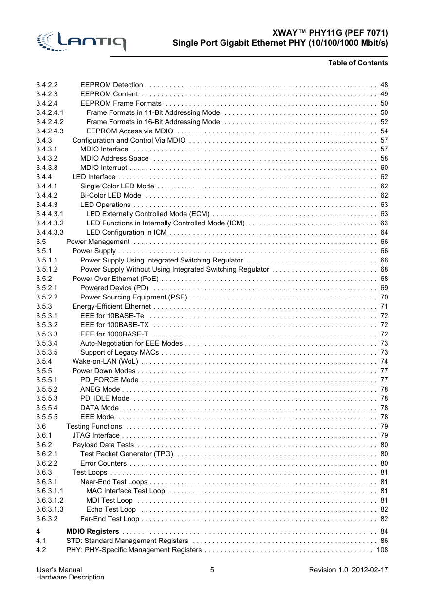
XWAY™ PHY11G (PEF 7071) Single Port Gigabit Ethernet PHY (10/100/1000 Mbit/s) Table of Contents EEPROM Detection . . . . . . . . . . . . . . . . . . . . . . . . . . . . . . . . . . . . . . . . . . . . . . . . . . . . . . . . . . . 48 EEPROM Content . . . . . . . . . . . . . . . . . . . . . . . . . . . . . . . . . . . . . . . . . . . . . . . . . . . . . . . . . . . . 49 EEPROM Frame Formats . . . . . . . . . . . . . . . . . . . . . . . . . . . . . . . . . . . . . . . . . . . . . . . . . . . . . . 50 Frame Formats in 11-Bit Addressing Mode . . . . . . . . . . . . . . . . . . . . . . . . . . . . . . . . . . . . . . . 50 Frame Formats in 16-Bit Addressing Mode . . . . . . . . . . . . . . . . . . . . . . . . . . . . . . . . . . . . . . . 52 EEPROM Access via MDIO . . . . . . . . . . . . . . . . . . . . . . . . . . . . . . . . . . . . . . . . . . . . . . . . . . . 54 Configuration and Control Via MDIO . . . . . . . . . . . . . . . . . . . . . . . . . . . . . . . . . . . . . . . . . . . . . . . . 57 MDIO Interface . . . . . . . . . . . . . . . . . . . . . . . . . . . . . . . . . . . . . . . . . . . . . . . . . . . . . . . . . . . . . . 57 MDIO Address Space . . . . . . . . . . . . . . . . . . . . . . . . . . . . . . . . . . . . . . . . . . . . . . . . . . . . . . . . . 58 MDIO Interrupt . . . . . . . . . . . . . . . . . . . . . . . . . . . . . . . . . . . . . . . . . . . . . . . . . . . . . . . . . . . . . . . 60 LED Interface . . . . . . . . . . . . . . . . . . . . . . . . . . . . . . . . . . . . . . . . . . . . . . . . . . . . . . . . . . . . . . . . . . 62 Single Color LED Mode . . . . . . . . . . . . . . . . . . . . . . . . . . . . . . . . . . . . . . . . . . . . . . . . . . . . . . . . 62 Bi-Color LED Mode . . . . . . . . . . . . . . . . . . . . . . . . . . . . . . . . . . . . . . . . . . . . . . . . . . . . . . . . . . . 62 LED Operations . . . . . . . . . . . . . . . . . . . . . . . . . . . . . . . . . . . . . . . . . . . . . . . . . . . . . . . . . . . . . . 63 LED Externally Controlled Mode (ECM) . . . . . . . . . . . . . . . . . . . . . . . . . . . . . . . . . . . . . . . . . . 63 LED Functions in Internally Controlled Mode (ICM) . . . . . . . . . . . . . . . . . . . . . . . . . . . . . . . . . 63 LED Configuration in ICM . . . . . . . . . . . . . . . . . . . . . . . . . . . . . . . . . . . . . . . . . . . . . . . . . . . . . 64 Power Management . . . . . . . . . . . . . . . . . . . . . . . . . . . . . . . . . . . . . . . . . . . . . . . . . . . . . . . . . . . . . . 66 Power Supply . . . . . . . . . . . . . . . . . . . . . . . . . . . . . . . . . . . . . . . . . . . . . . . . . . . . . . . . . . . . . . . . . . 66 Power Supply Using Integrated Switching Regulator . . . . . . . . . . . . . . . . . . . . . . . . . . . . . . . . . 66 Power Supply Without Using Integrated Switching Regulator . . . . . . . . . . . . . . . . . . . . . . . . . . . 68 Power Over Ethernet (PoE) . . . . . . . . . . . . . . . . . . . . . . . . . . . . . . . . . . . . . . . . . . . . . . . . . . . . . . . 68 Powered Device (PD) . . . . . . . . . . . . . . . . . . . . . . . . . . . . . . . . . . . . . . . . . . . . . . . . . . . . . . . . . 69 Power Sourcing Equipment (PSE) . . . . . . . . . . . . . . . . . . . . . . . . . . . . . . . . . . . . . . . . . . . . . . . . 70 Energy-Efficient Ethernet . . . . . . . . . . . . . . . . . . . . . . . . . . . . . . . . . . . . . . . . . . . . . . . . . . . . . . . . . 71 EEE for 10BASE-Te . . . . . . . . . . . . . . . . . . . . . . . . . . . . . . . . . . . . . . . . . . . . . . . . . . . . . . . . . . 72 EEE for 100BASE-TX . . . . . . . . . . . . . . . . . . . . . . . . . . . . . . . . . . . . . . . . . . . . . . . . . . . . . . . . . 72 EEE for 1000BASE-T . . . . . . . . . . . . . . . . . . . . . . . . . . . . . . . . . . . . . . . . . . . . . . . . . . . . . . . . . 72 Auto-Negotiation for EEE Modes . . . . . . . . . . . . . . . . . . . . . . . . . . . . . . . . . . . . . . . . . . . . . . . . . 73 Support of Legacy MACs . . . . . . . . . . . . . . . . . . . . . . . . . . . . . . . . . . . . . . . . . . . . . . . . . . . . . . . 73 Wake-on-LAN (WoL) . . . . . . . . . . . . . . . . . . . . . . . . . . . . . . . . . . . . . . . . . . . . . . . . . . . . . . . . . . . . 74 Power Down Modes . . . . . . . . . . . . . . . . . . . . . . . . . . . . . . . . . . . . . . . . . . . . . . . . . . . . . . . . . . . . . 77 PD_FORCE Mode . . . . . . . . . . . . . . . . . . . . . . . . . . . . . . . . . . . . . . . . . . . . . . . . . . . . . . . . . . . . 77 ANEG Mode . . . . . . . . . . . . . . . . . . . . . . . . . . . . . . . . . . . . . . . . . . . . . . . . . . . . . . . . . . . . . . . . . 78 PD_IDLE Mode . . . . . . . . . . . . . . . . . . . . . . . . . . . . . . . . . . . . . . . . . . . . . . . . . . . . . . . . . . . . . . 78 DATA Mode . . . . . . . . . . . . . . . . . . . . . . . . . . . . . . . . . . . . . . . . . . . . . . . . . . . . . . . . . . . . . . . . . 78 EEE Mode . . . . . . . . . . . . . . . . . . . . . . . . . . . . . . . . . . . . . . . . . . . . . . . . . . . . . . . . . . . . . . . . . . 78 Testing Functions . . . . . . . . . . . . . . . . . . . . . . . . . . . . . . . . . . . . . . . . . . . . . . . . . . . . . . . . . . . . . . . . 79 JTAG Interface . . . . . . . . . . . . . . . . . . . . . . . . . . . . . . . . . . . . . . . . . . . . . . . . . . . . . . . . . . . . . . . . . 79 Payload Data Tests . . . . . . . . . . . . . . . . . . . . . . . . . . . . . . . . . . . . . . . . . . . . . . . . . . . . . . . . . . . . . 80 Test Packet Generator (TPG) . . . . . . . . . . . . . . . . . . . . . . . . . . . . . . . . . . . . . . . . . . . . . . . . . . . 80 Error Counters . . . . . . . . . . . . . . . . . . . . . . . . . . . . . . . . . . . . . . . . . . . . . . . . . . . . . . . . . . . . . . . 80 Test Loops . . . . . . . . . . . . . . . . . . . . . . . . . . . . . . . . . . . . . . . . . . . . . . . . . . . . . . . . . . . . . . . . . . . . 81 Near-End Test Loops . . . . . . . . . . . . . . . . . . . . . . . . . . . . . . . . . . . . . . . . . . . . . . . . . . . . . . . . . . 81 MAC Interface Test Loop . . . . . . . . . . . . . . . . . . . . . . . . . . . . . . . . . . . . . . . . . . . . . . . . . . . . . 81 MDI Test Loop . . . . . . . . . . . . . . . . . . . . . . . . . . . . . . . . . . . . . . . . . . . . . . . . . . . . . . . . . . . . . 81 Echo Test Loop . . . . . . . . . . . . . . . . . . . . . . . . . . . . . . . . . . . . . . . . . . . . . . . . . . . . . . . . . . . . 82 Far-End Test Loop . . . . . . . . . . . . . . . . . . . . . . . . . . . . . . . . . . . . . . . . . . . . . . . . . . . . . . . . . . . . 82 MDIO Registers . . . . . . . . . . . . . . . . . . . . . . . . . . . . . . . . . . . . . . . . . . . . . . . . . . . . . . . . . . . . . . . . . 84 STD: Standard Management Registers . . . . . . . . . . . . . . . . . . . . . . . . . . . . . . . . . . . . . . . . . . . . . . . 86 PHY: PHY-Specific Management Registers . . . . . . . . . . . . . . . . . . . . . . . . . . . . . . . . . . . . . . . . . . . 108 3.4.2.2 3.4.2.3 3.4.2.4 3.4.2.4.1 3.4.2.4.2 3.4.2.4.3 3.4.3 3.4.3.1 3.4.3.2 3.4.3.3 3.4.4 3.4.4.1 3.4.4.2 3.4.4.3 3.4.4.3.1 3.4.4.3.2 3.4.4.3.3 3.5 3.5.1 3.5.1.1 3.5.1.2 3.5.2 3.5.2.1 3.5.2.2 3.5.3 3.5.3.1 3.5.3.2 3.5.3.3 3.5.3.4 3.5.3.5 3.5.4 3.5.5 3.5.5.1 3.5.5.2 3.5.5.3 3.5.5.4 3.5.5.5 3.6 3.6.1 3.6.2 3.6.2.1 3.6.2.2 3.6.3 3.6.3.1 3.6.3.1.1 3.6.3.1.2 3.6.3.1.3 3.6.3.2 4 4.1 4.2 User’s Manual Hardware Description 5 Revision 1.0, 2012-02-17
XWAY™ PHY11G (PEF 7071) Single Port Gigabit Ethernet PHY (10/100/1000 Mbit/s) Table of Contents MMD Registers . . . . . . . . . . . . . . . . . . . . . . . . . . . . . . . . . . . . . . . . . . . . . . . . . . . . . . . . . . . . . . . . 132 EEE: Standard EEE Registers for MMD=0x03 . . . . . . . . . . . . . . . . . . . . . . . . . . . . . . . . . . . . . . . . . 134 ANEG: Standard Auto-Negotiation Registers for MMD=0x07 . . . . . . . . . . . . . . . . . . . . . . . . . . . . . 138 EEPROM: EEPROM Address Space (MMD=0x1E) . . . . . . . . . . . . . . . . . . . . . . . . . . . . . . . . . . . . . 140 INTERNAL: Internal Address Space (MMD=0x1F) . . . . . . . . . . . . . . . . . . . . . . . . . . . . . . . . . . . . . . 141 Electrical Characteristics . . . . . . . . . . . . . . . . . . . . . . . . . . . . . . . . . . . . . . . . . . . . . . . . . . . . . . . . 155 Absolute Maximum Ratings . . . . . . . . . . . . . . . . . . . . . . . . . . . . . . . . . . . . . . . . . . . . . . . . . . . . . . . 155 Operating Range . . . . . . . . . . . . . . . . . . . . . . . . . . . . . . . . . . . . . . . . . . . . . . . . . . . . . . . . . . . . . . . 156 Recommended Operating Conditions . . . . . . . . . . . . . . . . . . . . . . . . . . . . . . . . . . . . . . . . . . . . . . . . 156 Power-Up Sequence . . . . . . . . . . . . . . . . . . . . . . . . . . . . . . . . . . . . . . . . . . . . . . . . . . . . . . . . . . . . . 156 DC Characteristics . . . . . . . . . . . . . . . . . . . . . . . . . . . . . . . . . . . . . . . . . . . . . . . . . . . . . . . . . . . . . . 157 Digital Interfaces . . . . . . . . . . . . . . . . . . . . . . . . . . . . . . . . . . . . . . . . . . . . . . . . . . . . . . . . . . . . . . 157 GPIO Interfaces . . . . . . . . . . . . . . . . . . . . . . . . . . . . . . . . . . . . . . . . . . . . . . . . . . . . . . . . . . . . . 157 MII Receive Interface . . . . . . . . . . . . . . . . . . . . . . . . . . . . . . . . . . . . . . . . . . . . . . . . . . . . . . . . . 158 MII Transmit Interface . . . . . . . . . . . . . . . . . . . . . . . . . . . . . . . . . . . . . . . . . . . . . . . . . . . . . . . . 158 LED Interface . . . . . . . . . . . . . . . . . . . . . . . . . . . . . . . . . . . . . . . . . . . . . . . . . . . . . . . . . . . . . . . 158 JTAG Interface . . . . . . . . . . . . . . . . . . . . . . . . . . . . . . . . . . . . . . . . . . . . . . . . . . . . . . . . . . . . . . 159 Twisted-Pair Interface . . . . . . . . . . . . . . . . . . . . . . . . . . . . . . . . . . . . . . . . . . . . . . . . . . . . . . . . . . 159 SGMII Interface . . . . . . . . . . . . . . . . . . . . . . . . . . . . . . . . . . . . . . . . . . . . . . . . . . . . . . . . . . . . . . . 159 1000BASE-X Interface . . . . . . . . . . . . . . . . . . . . . . . . . . . . . . . . . . . . . . . . . . . . . . . . . . . . . . . . . . 159 AC Characteristics . . . . . . . . . . . . . . . . . . . . . . . . . . . . . . . . . . . . . . . . . . . . . . . . . . . . . . . . . . . . . . 160 Reset . . . . . . . . . . . . . . . . . . . . . . . . . . . . . . . . . . . . . . . . . . . . . . . . . . . . . . . . . . . . . . . . . . . . . . . 160 Power Supply . . . . . . . . . . . . . . . . . . . . . . . . . . . . . . . . . . . . . . . . . . . . . . . . . . . . . . . . . . . . . . . . . 161 Input Clock . . . . . . . . . . . . . . . . . . . . . . . . . . . . . . . . . . . . . . . . . . . . . . . . . . . . . . . . . . . . . . . . . . . 161 Output Clock . . . . . . . . . . . . . . . . . . . . . . . . . . . . . . . . . . . . . . . . . . . . . . . . . . . . . . . . . . . . . . . . . 162 MDIO Interface . . . . . . . . . . . . . . . . . . . . . . . . . . . . . . . . . . . . . . . . . . . . . . . . . . . . . . . . . . . . . . . 162 RMII Interface . . . . . . . . . . . . . . . . . . . . . . . . . . . . . . . . . . . . . . . . . . . . . . . . . . . . . . . . . . . . . . . . 163 RGMII Interface . . . . . . . . . . . . . . . . . . . . . . . . . . . . . . . . . . . . . . . . . . . . . . . . . . . . . . . . . . . . . . . 164 Transmit Timing Characteristics . . . . . . . . . . . . . . . . . . . . . . . . . . . . . . . . . . . . . . . . . . . . . . . . 164 Receive Timing Characteristics . . . . . . . . . . . . . . . . . . . . . . . . . . . . . . . . . . . . . . . . . . . . . . . . . 165 RTBI Interface . . . . . . . . . . . . . . . . . . . . . . . . . . . . . . . . . . . . . . . . . . . . . . . . . . . . . . . . . . . . . . . . 167 Transmit Timing Characteristics . . . . . . . . . . . . . . . . . . . . . . . . . . . . . . . . . . . . . . . . . . . . . . . . 167 Receive Timing Characteristics . . . . . . . . . . . . . . . . . . . . . . . . . . . . . . . . . . . . . . . . . . . . . . . . . 168 SGMII Interface . . . . . . . . . . . . . . . . . . . . . . . . . . . . . . . . . . . . . . . . . . . . . . . . . . . . . . . . . . . . . . . 169 Transmit Timing Characteristics . . . . . . . . . . . . . . . . . . . . . . . . . . . . . . . . . . . . . . . . . . . . . . . . 169 Receive Timing Characteristics . . . . . . . . . . . . . . . . . . . . . . . . . . . . . . . . . . . . . . . . . . . . . . . . . 170 1000BASE-X Interface . . . . . . . . . . . . . . . . . . . . . . . . . . . . . . . . . . . . . . . . . . . . . . . . . . . . . . . . . . 171 Transmit Timing Characteristics . . . . . . . . . . . . . . . . . . . . . . . . . . . . . . . . . . . . . . . . . . . . . . . . 171 Receive Timing Characteristics . . . . . . . . . . . . . . . . . . . . . . . . . . . . . . . . . . . . . . . . . . . . . . . . . 172 Twisted-Pair Interface . . . . . . . . . . . . . . . . . . . . . . . . . . . . . . . . . . . . . . . . . . . . . . . . . . . . . . . . . . 172 Isolation Requirements . . . . . . . . . . . . . . . . . . . . . . . . . . . . . . . . . . . . . . . . . . . . . . . . . . . . . . . . . . . 172 External Circuitry . . . . . . . . . . . . . . . . . . . . . . . . . . . . . . . . . . . . . . . . . . . . . . . . . . . . . . . . . . . . . . . 173 Crystal . . . . . . . . . . . . . . . . . . . . . . . . . . . . . . . . . . . . . . . . . . . . . . . . . . . . . . . . . . . . . . . . . . . . . . 173 LED . . . . . . . . . . . . . . . . . . . . . . . . . . . . . . . . . . . . . . . . . . . . . . . . . . . . . . . . . . . . . . . . . . . . . . . . 174 Transformer (Magnetics) . . . . . . . . . . . . . . . . . . . . . . . . . . . . . . . . . . . . . . . . . . . . . . . . . . . . . . . . 175 RJ45 Plug . . . . . . . . . . . . . . . . . . . . . . . . . . . . . . . . . . . . . . . . . . . . . . . . . . . . . . . . . . . . . . . . . . . 177 Twisted-Pair Common-Mode Rejection and Termination Circuitry . . . . . . . . . . . . . . . . . . . . . . . . 178 SGMII Interface . . . . . . . . . . . . . . . . . . . . . . . . . . . . . . . . . . . . . . . . . . . . . . . . . . . . . . . . . . . . . . . 179 1000BASE-X Interface . . . . . . . . . . . . . . . . . . . . . . . . . . . . . . . . . . . . . . . . . . . . . . . . . . . . . . . . . . 181 Package Outline . . . . . . . . . . . . . . . . . . . . . . . . . . . . . . . . . . . . . . . . . . . . . . . . . . . . . . . . . . . . . . . 182 5 5.1 5.2 5.3 5.4 6 6.1 6.2 6.3 6.4 6.5 6.5.1 6.5.1.1 6.5.1.2 6.5.1.3 6.5.1.4 6.5.1.5 6.5.2 6.5.3 6.5.4 6.6 6.6.1 6.6.2 6.6.3 6.6.4 6.6.5 6.6.6 6.6.7 6.6.7.1 6.6.7.2 6.6.8 6.6.8.1 6.6.8.2 6.6.9 6.6.9.1 6.6.9.2 6.6.10 6.6.10.1 6.6.10.2 6.6.11 6.7 6.8 6.8.1 6.8.2 6.8.3 6.8.4 6.8.5 6.8.6 6.8.7 7 User’s Manual Hardware Description 6 Revision 1.0, 2012-02-17
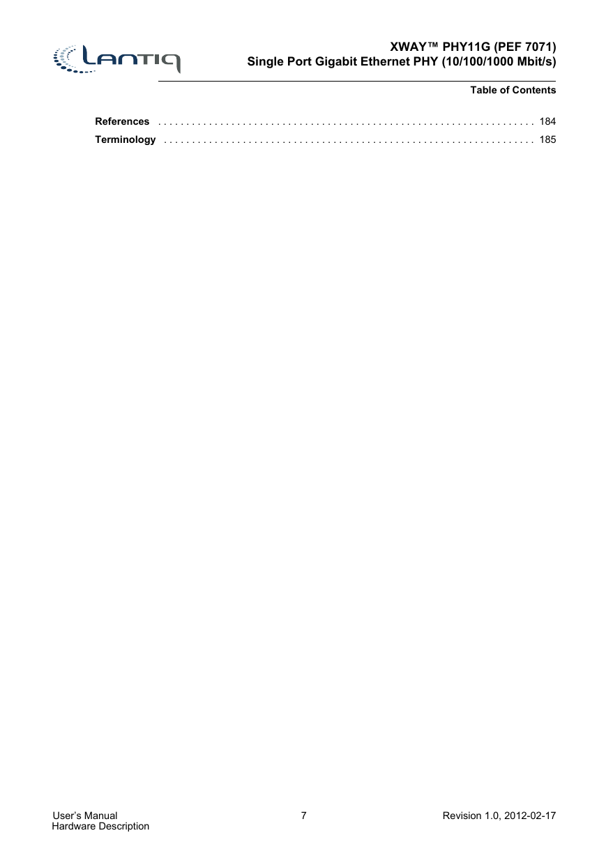
XWAY™ PHY11G (PEF 7071) Single Port Gigabit Ethernet PHY (10/100/1000 Mbit/s) Table of Contents References . . . . . . . . . . . . . . . . . . . . . . . . . . . . . . . . . . . . . . . . . . . . . . . . . . . . . . . . . . . . . . . . . . . 184 Terminology . . . . . . . . . . . . . . . . . . . . . . . . . . . . . . . . . . . . . . . . . . . . . . . . . . . . . . . . . . . . . . . . . . 185 User’s Manual Hardware Description 7 Revision 1.0, 2012-02-17
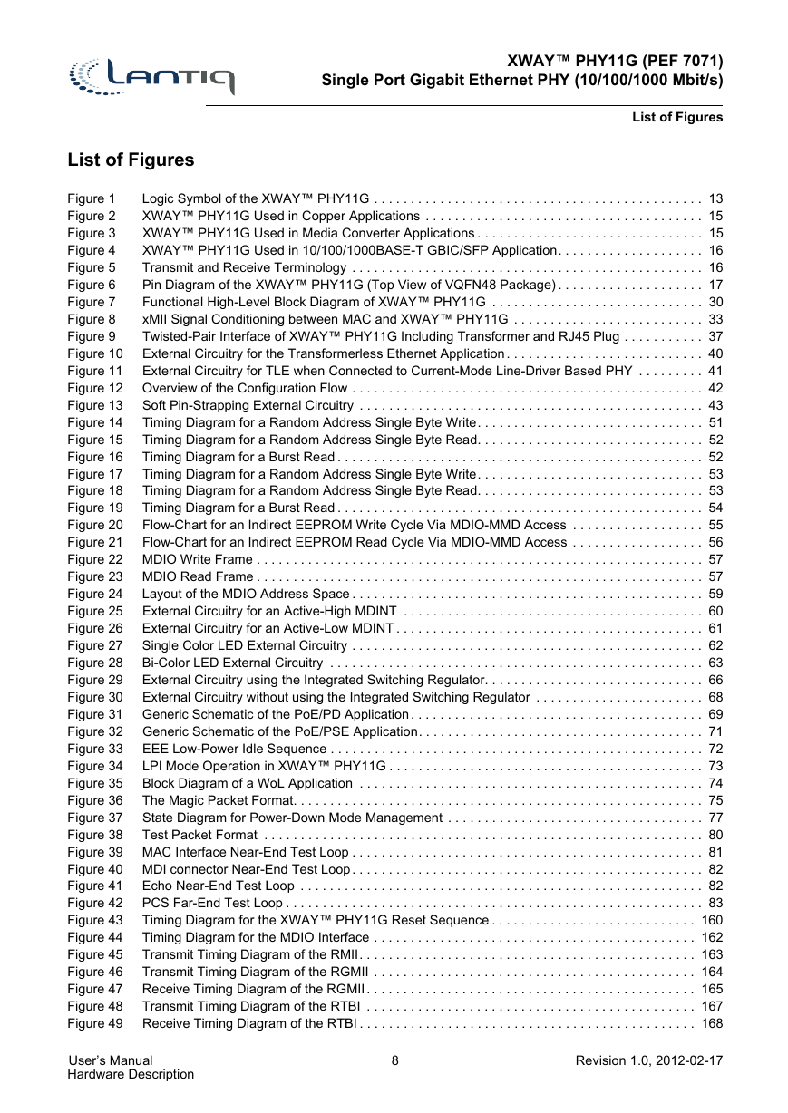
XWAY™ PHY11G (PEF 7071) Single Port Gigabit Ethernet PHY (10/100/1000 Mbit/s) List of Figures List of Figures Figure 1 Logic Symbol of the XWAY™ PHY11G . . . . . . . . . . . . . . . . . . . . . . . . . . . . . . . . . . . . . . . . . . . . . 13 Figure 2 XWAY™ PHY11G Used in Copper Applications . . . . . . . . . . . . . . . . . . . . . . . . . . . . . . . . . . . . . . 15 Figure 3 XWAY™ PHY11G Used in Media Converter Applications . . . . . . . . . . . . . . . . . . . . . . . . . . . . . . . 15 Figure 4 XWAY™ PHY11G Used in 10/100/1000BASE-T GBIC/SFP Application. . . . . . . . . . . . . . . . . . . . 16 Figure 5 Transmit and Receive Terminology . . . . . . . . . . . . . . . . . . . . . . . . . . . . . . . . . . . . . . . . . . . . . . . . 16 Figure 6 Pin Diagram of the XWAY™ PHY11G (Top View of VQFN48 Package) . . . . . . . . . . . . . . . . . . . . 17 Figure 7 Functional High-Level Block Diagram of XWAY™ PHY11G . . . . . . . . . . . . . . . . . . . . . . . . . . . . . 30 Figure 8 xMII Signal Conditioning between MAC and XWAY™ PHY11G . . . . . . . . . . . . . . . . . . . . . . . . . . 33 Figure 9 Twisted-Pair Interface of XWAY™ PHY11G Including Transformer and RJ45 Plug . . . . . . . . . . . 37 Figure 10 External Circuitry for the Transformerless Ethernet Application. . . . . . . . . . . . . . . . . . . . . . . . . . . 40 Figure 11 External Circuitry for TLE when Connected to Current-Mode Line-Driver Based PHY . . . . . . . . . 41 Figure 12 Overview of the Configuration Flow . . . . . . . . . . . . . . . . . . . . . . . . . . . . . . . . . . . . . . . . . . . . . . . . 42 Soft Pin-Strapping External Circuitry . . . . . . . . . . . . . . . . . . . . . . . . . . . . . . . . . . . . . . . . . . . . . . . 43 Figure 13 Timing Diagram for a Random Address Single Byte Write. . . . . . . . . . . . . . . . . . . . . . . . . . . . . . . 51 Figure 14 Figure 15 Timing Diagram for a Random Address Single Byte Read. . . . . . . . . . . . . . . . . . . . . . . . . . . . . . . 52 Timing Diagram for a Burst Read . . . . . . . . . . . . . . . . . . . . . . . . . . . . . . . . . . . . . . . . . . . . . . . . . . 52 Figure 16 Timing Diagram for a Random Address Single Byte Write. . . . . . . . . . . . . . . . . . . . . . . . . . . . . . . 53 Figure 17 Timing Diagram for a Random Address Single Byte Read. . . . . . . . . . . . . . . . . . . . . . . . . . . . . . . 53 Figure 18 Figure 19 Timing Diagram for a Burst Read . . . . . . . . . . . . . . . . . . . . . . . . . . . . . . . . . . . . . . . . . . . . . . . . . . 54 Flow-Chart for an Indirect EEPROM Write Cycle Via MDIO-MMD Access . . . . . . . . . . . . . . . . . . 55 Figure 20 Figure 21 Flow-Chart for an Indirect EEPROM Read Cycle Via MDIO-MMD Access . . . . . . . . . . . . . . . . . . 56 Figure 22 MDIO Write Frame . . . . . . . . . . . . . . . . . . . . . . . . . . . . . . . . . . . . . . . . . . . . . . . . . . . . . . . . . . . . . 57 Figure 23 MDIO Read Frame . . . . . . . . . . . . . . . . . . . . . . . . . . . . . . . . . . . . . . . . . . . . . . . . . . . . . . . . . . . . . 57 Layout of the MDIO Address Space . . . . . . . . . . . . . . . . . . . . . . . . . . . . . . . . . . . . . . . . . . . . . . . . 59 Figure 24 External Circuitry for an Active-High MDINT . . . . . . . . . . . . . . . . . . . . . . . . . . . . . . . . . . . . . . . . . 60 Figure 25 Figure 26 External Circuitry for an Active-Low MDINT . . . . . . . . . . . . . . . . . . . . . . . . . . . . . . . . . . . . . . . . . . 61 Single Color LED External Circuitry . . . . . . . . . . . . . . . . . . . . . . . . . . . . . . . . . . . . . . . . . . . . . . . . 62 Figure 27 Bi-Color LED External Circuitry . . . . . . . . . . . . . . . . . . . . . . . . . . . . . . . . . . . . . . . . . . . . . . . . . . . 63 Figure 28 External Circuitry using the Integrated Switching Regulator. . . . . . . . . . . . . . . . . . . . . . . . . . . . . . 66 Figure 29 Figure 30 External Circuitry without using the Integrated Switching Regulator . . . . . . . . . . . . . . . . . . . . . . . 68 Figure 31 Generic Schematic of the PoE/PD Application. . . . . . . . . . . . . . . . . . . . . . . . . . . . . . . . . . . . . . . . 69 Figure 32 Generic Schematic of the PoE/PSE Application. . . . . . . . . . . . . . . . . . . . . . . . . . . . . . . . . . . . . . . 71 EEE Low-Power Idle Sequence . . . . . . . . . . . . . . . . . . . . . . . . . . . . . . . . . . . . . . . . . . . . . . . . . . . 72 Figure 33 Figure 34 LPI Mode Operation in XWAY™ PHY11G . . . . . . . . . . . . . . . . . . . . . . . . . . . . . . . . . . . . . . . . . . . 73 Block Diagram of a WoL Application . . . . . . . . . . . . . . . . . . . . . . . . . . . . . . . . . . . . . . . . . . . . . . . 74 Figure 35 The Magic Packet Format. . . . . . . . . . . . . . . . . . . . . . . . . . . . . . . . . . . . . . . . . . . . . . . . . . . . . . . . 75 Figure 36 Figure 37 State Diagram for Power-Down Mode Management . . . . . . . . . . . . . . . . . . . . . . . . . . . . . . . . . . . 77 Figure 38 Test Packet Format . . . . . . . . . . . . . . . . . . . . . . . . . . . . . . . . . . . . . . . . . . . . . . . . . . . . . . . . . . . . 80 Figure 39 MAC Interface Near-End Test Loop . . . . . . . . . . . . . . . . . . . . . . . . . . . . . . . . . . . . . . . . . . . . . . . . 81 Figure 40 MDI connector Near-End Test Loop. . . . . . . . . . . . . . . . . . . . . . . . . . . . . . . . . . . . . . . . . . . . . . . . 82 Echo Near-End Test Loop . . . . . . . . . . . . . . . . . . . . . . . . . . . . . . . . . . . . . . . . . . . . . . . . . . . . . . . 82 Figure 41 Figure 42 PCS Far-End Test Loop . . . . . . . . . . . . . . . . . . . . . . . . . . . . . . . . . . . . . . . . . . . . . . . . . . . . . . . . . 83 Timing Diagram for the XWAY™ PHY11G Reset Sequence . . . . . . . . . . . . . . . . . . . . . . . . . . . . 160 Figure 43 Timing Diagram for the MDIO Interface . . . . . . . . . . . . . . . . . . . . . . . . . . . . . . . . . . . . . . . . . . . . 162 Figure 44 Transmit Timing Diagram of the RMII. . . . . . . . . . . . . . . . . . . . . . . . . . . . . . . . . . . . . . . . . . . . . . 163 Figure 45 Figure 46 Transmit Timing Diagram of the RGMII . . . . . . . . . . . . . . . . . . . . . . . . . . . . . . . . . . . . . . . . . . . . 164 Receive Timing Diagram of the RGMII. . . . . . . . . . . . . . . . . . . . . . . . . . . . . . . . . . . . . . . . . . . . . 165 Figure 47 Transmit Timing Diagram of the RTBI . . . . . . . . . . . . . . . . . . . . . . . . . . . . . . . . . . . . . . . . . . . . . 167 Figure 48 Figure 49 Receive Timing Diagram of the RTBI . . . . . . . . . . . . . . . . . . . . . . . . . . . . . . . . . . . . . . . . . . . . . . 168 User’s Manual Hardware Description 8 Revision 1.0, 2012-02-17
分享到:
收藏