IEEE TRANSACTIONS ON INSTRUMENTATION AND MEASUREMENT, VOL. 65, NO. 2, FEBRUARY 2016
467
A Linear Kalman Filter for MARG Orientation
Estimation Using the Algebraic
Quaternion Algorithm
Roberto G. Valenti, Ivan Dryanovski, and Jizhong Xiao, Senior Member, IEEE
Abstract— Real-time orientation estimation using low-cost
inertial sensors is essential for all the applications where size and
power consumption are critical constraints. Such applications
include robotics, human motion analysis, and mobile devices.
This paper presents a linear Kalman filter for magnetic angular
rate and gravity sensors that processes angular rate, acceleration,
and magnetic field data to obtain an estimation of the orien-
tation in quaternion representation. Acceleration and magnetic
field observations are preprocessed through a novel external
algorithm, which computes the quaternion orientation as the
composition of two algebraic quaternions. The decoupled nature
of the two quaternions makes the roll and pitch components of
the orientation immune to magnetic disturbances. The external
algorithm reduces the complexity of
the filter, making the
measurement equations linear. Real-time implementation and the
test results of the Kalman filter are presented and compared
against a typical quaternion-based extended Kalman filter and a
constant gain filter based on the gradient-descent algorithm.
Index Terms— Inertial sensors, Kalman filtering, magnetic
sensors, orientation estimation, quaternions.
I. INTRODUCTION
I NERTIAL and magnetic sensors are largely used to
estimate the orientation of a rigid body with respect to an
inertial frame. Their use ranges from aerospace and unmanned
vehicles to man–machine iteration and robotics. The devel-
opment of low-cost and lightweight microelectromechanical
systems has allowed smaller and cheaper inertial sensors to
be adopted for an even wider range of applications, such as
human motion tracking [1], [2], microaerial vehicles [3], [4],
and mobile devices [5], [6].
An inertial measurement unit (IMU) is a combination of
sensors that typically includes a triaxis accelerometer and
triaxis gyroscope. In addition,
the IMU has a triaxis
magnetometer,
is referred to as magnetic angular rate
and gravity (MARG). The accelerometer observes the IMU’s
proper acceleration by measuring the weight experienced by
if
it
Manuscript received May 20, 2015; revised September 18, 2015; accepted
September 19, 2015. Date of publication December 3, 2015; date of
current version January 4, 2016. This work was supported in part by
the U.S. Army Research Office under Grant W911NF-09-1-0565 and
in part by the U.S. National Science Foundation under Grant IIS-0644127 and
Grant CBET-1160046. The Associate Editor coordinating the review process
was Dr. Huang-Chen Lee. (Corresponding author: Jizhong Xiao.)
R. G. Valenti and J. Xiao are with the Department of Electrical Engineer-
ing, The City College of New York, New York, NY 10031 USA (e-mail:
rvalent00@citymail.cuny.edu; jxiao@ccny.cuny.edu).
I. Dryanovski is with the Department of Computer Science, The Graduate
Center, The City University of New York, New York, NY 10016 USA (e-mail:
idryanovski@gc.cuny.edu).
Color versions of one or more of the figures in this paper are available
online at http://ieeexplore.ieee.org.
Digital Object Identifier 10.1109/TIM.2015.2498998
a test mass that is at rest in the local sensor frame. When
the accelerometer is placed in a gravitational field, and is not
subjected to external nongravitational accelerations, it mea-
sures the specific force opposing the weight produced by
the gravitational pull, and thus, it may be used to infer the
magnitude and direction of the gravitational field. Therefore,
an accelerometer that is at rest on the surface of the earth
measures a vector of magnitude 1 g pointing upward in the
local tangent plane coordinate frame.
To obtain an estimation of the orientation, acceleration
and magnetic field measurements are fused together with
angular rate readings from the gyroscope by means of a
specific orientation estimation algorithm. Many approaches
have been studied for this purpose. We can classify them into
two categories depending on whether they use a stochastic
approach or a frequency analysis. Among the stochastic
approaches, Kalman filter-based techniques are by far the most
common ones. They adopt a probabilistic determination of the
state modeled as a Gaussian distribution given the system’s
model. They are widely used in aerospace applications [7], [8],
human motion analysis [9]–[11], and robotics [12], [13].
Filters based on frequency analysis are a common alterna-
tive to Kalman filter (KFs) because of their simplicity and
effectiveness. Complementary observers [14]–[16] and other
constant gain filters [17] use an analysis in the frequency
domain to filter the signals coming from different sources and
combine them together to obtain a more accurate orientation
estimation without any statistical description. A typical draw-
back of a constant gain filter is the inability to adapt the weight
of the different sources of information when their accuracy is
affected. More recent filters address this problem by adopting
an adaptive gain algorithm [18]–[20], which automatically
changes the gain value according to the perceived external
conditions, such as nongravitational acceleration and magnetic
disturbances. A survey of other nonlinear estimation methods
can be found in [21].
Most of the recent sensor fusion algorithms for inertial/
magnetic sensors provide an orientation estimation in quater-
nion form. Unlike Euler angles, quaternions do not suffer from
the singularity configuration known as the gimbal lock. Among
all the orientation representations that avoid the gimbal lock,
quaternions have the minimal number of parameters, hence
requiring less computation time. Furthermore, the quaternion
representation offers a linear formulation of the orientation
dynamics and rotations of vectors are simply performed by
quaternion multiplications.
0018-9456 © 2015 IEEE. Personal use is permitted, but republication/redistribution requires IEEE permission.
See http://www.ieee.org/publications_standards/publications/rights/index.html for more information.
�
468
IEEE TRANSACTIONS ON INSTRUMENTATION AND MEASUREMENT, VOL. 65, NO. 2, FEBRUARY 2016
The extended Kalman filter is the basis of IMU-based
orientation estimations. It can be implemented such that
the state includes the orientation components for a direct
orientation estimation or with the state composed of the
orientation error whose estimation will be used to indi-
rectly obtain the final orientation. These two KF approaches
are referred to as direct extended Kalman filter(EKF)
and indirect EKF.
the orientation is expressed in
quaternion form,
the direct and indirect EKFs are com-
monly known as additive EKF (AEKF) and multiplicative
EKF (MEKF), respectively, due to the quaternion error form
that distinguishes each case. A discussion about the differences
between the two methods can be found in [22].
If
In their first approach, Marins et al. [9] present an AEKF
to estimate the orientation in quaternion form and the angular
velocity vector from a MARG sensor. Sabatini [10] directly
estimates the quaternion orientation adopting an EKF, which is
also used to estimate accelerometer and magnetometer biases
by state augmentation for online calibration. Sabatini [24]
presents an EKF where the state, composed of the quaternion
components, is augmented with magnetic distortion vector,
modeled as a Gauss–Markov process, to reduce the heading
drift in magnetically nonhomogeneous environments. More-
over, the author presents the observability analysis of the
filter. Zhang et al. [25] propose a quaternion-based Kalman
filter, which adopts a linear process and measurement model
thanks to the manipulation of acceleration and magnetometer
readings to establish the linear pseudomeasurement equation.
Such a linear KF is able to deal with temporary external inter-
ference such as nongravitational acceleration and magnetic
disturbances by means of a vector selection scheme based on
the predicted measurement.
Trawny and Roumeliotis [26] present an indirect EKF where
the error vector is expressed as the small rotation between the
estimated and the true orientation of the local frame of refer-
ence and is defined as a quaternion multiplication (from here
the term multiplicative). This approach reduces the size of
the state vector and avoids any possible instability of the
error covariance. A similar approach is adopted in the MEKF
in [27]. Suh [28] proposes a quaternion-based indirect Kalman
filter with a two-step measurement update and adaptive
estimation of external acceleration. The two-step measurement
update consists of an accelerometer measurement update and
a magnetic sensor measurement update. The two updates are
decoupled such that acceleration data are used only to update
roll and pitch components of the orientation, while the second
step uses only magnetometer measurements to correct the yaw.
Therefore, magnetic disturbances will not affect the roll and
pitch. Because of the separation of the measurement update
equation into two stages, the algorithm is rather complicated.
Hence, Suh et al. [29] propose a new measurement equation
for the quaternion-based indirect Kalman filter, where roll and
pitch are only slightly affected by the magnetic sensor.
To reduce the complexity of a quaternion-based EKF
and avoid the linearization procedure, which might reduce
the convergence rate and introduce approximation errors,
a two-layer filter architecture can be adopted. The first layer is
dedicated to an external algorithm to evaluate the quaternion
orientation from acceleration and magnetic field data by
solving the Wahba’s problem [30]. The second layer is a linear
Kalman filter that applies the quaternion output of the first
layer as the input of the measurement process. This strategy
has been applied by many researchers using different external
estimators of the quaternion orientation. Marins et al. [9], in
their second approach, and Yun et al. [23] use a Gauss–Newton
optimization algorithm. Yun and Bachmann [31] apply the
quaternion estimator (QUEST) [32], and Seo et al. [33]
use the factored quaternion algorithm (FQA) [34]. The main
difference between these methods is the computational speed
of the external QUEST. Most of these methods find the
quaternion orientation as output of a minimization technique
by minimizing a cost function through a sequence of itera-
tions. Usually, in KF applications, only one iteration is used
because generally the rate of convergence of the optimization
algorithm is higher than the angular speed. However, when the
orientation variation rate increases, the optimization algorithm
reduces its performance, adding error to the estimate produced
by the filter. The FQA computes the orientation of a rigid
body based on earth gravity and magnetic field measure-
ments. The quaternion orientation is estimated by analyzing
a series of three sequential rotations. This approach reduces
the orientation error caused by the presence of local magnetic
disturbances, only into the error in the yaw component main-
taining the accuracy of the QUEST algorithm. Nevertheless,
the FQA is computationally more efficient than QUEST by
about 25% [34].
In this paper, we describe a linear Kalman filter using
the two-layer structure described above, adopting a novel
external QUEST. The novel algorithm finds a quaternion orien-
tation by solving Whaba’s problem through the processing of
gravity and magnetic field observations. Unlike the FQA, the
presented method computes the orientation as a sequence of
only two rotations. The first rotation defines a tilt quaternion,
giving information about
the roll and pitch angles, while
the second heading quaternion contains the yaw angle. Both
quaternions are found as an algebraic solution of a system
instead of the result of an optimization problem. By construc-
tion, the output quaternion does not suffer from singularity
states; moreover, the heading quaternion, which is found by
processing magnetic field data, does not change the bearing
information contained in the tilt quaternion. Therefore, in the
case of magnetic disturbances that alter the reference direction
of the magnetic north, the error will affect only the yaw
angle.
Furthermore, we derive the covariance matrix of
the
orientation quaternion via propagation of the acceleration
and magnetic field’s standard deviations. To accomplish this,
we approximate the quaternion as a normally distributed
random vector. This derivation facilitates the use of the
quaternion as the correction measurement in the Kalman filter
framework.
II. BACKGROUND THEORY
Any arbitrary orientation in the 3-D space of frame A with
respect to frame B can be represented by a unit quaternion B
Aq
�
VALENTI et al.: LINEAR KALMAN FILTER FOR MARG ORIENTATION ESTIMATION USING AQUA
469
defined as follows:
⎤
⎥⎥⎦ =
⎡
⎢⎢⎣
q0
q1
q2
q3
Aq =
B
⎡
⎢⎢⎢⎢⎢⎢⎢⎣
cos
ex sin
ey sin
ez sin
⎤
⎥⎥⎥⎥⎥⎥⎥⎦
α
2
α
2
α
2
α
2
(1)
where α is the rotation angle and e is the unit vector that
represents the rotation axis. The quaternion conjugate of B
Aq,
given its unit norm, is equivalent to the inverse quaternion
and describes the inverse rotation. Therefore, the conjugate
quaternion can be used to represent the orientation of frame B
relative to frame A, as defined in the following:
The rotation defined in (5) can be written in matrix form as in
B v = R
B
Aq
Av
(8)
B
Aq
where R
, which belongs to the 3-D special orthogonal
group SO(3), is the direct cosine matrix given in terms of the
orientation quaternion B
⎤
⎡
+ q2
−q2
q2
⎥⎦.
⎢⎣
2(q1q2 + q0q3)
0
2(q1q3 −q0q2)
Aq as shown in the following:
2(q1q2 −q0q3)
−q2
− q2
q2
2(q2q3 + q0q1)
0
2(q1q3 + q0q2)
2(q2q3 −q0q1)
−q2
+ q2
q2
0
+ q2
−q2
−q2
1
2
3
1
2
3
1
2
3
(9)
Given the properties of the elements of SO(3), the inverse
rotation can be defined as
A
Bq
Bv = RT
Av = R
(10)
B
Aq
B v.
∗ = A
Bq =
B
Aq
⎤
⎥⎥⎦.
⎡
⎢⎢⎣
q0−q1−q2−q3
(2)
III. ALGEBRAIC QUATERNION ALGORITHM
The orientation quaternion after a sequence of rotations
can be easily found by quaternion multiplication where each
quaternion represents the orientation of a frame with respect
to the rotated one. For example, given three frames A, B,
and C, and given the quaternion B
Aq orientation of frame A
expressed with respect to frame B, and given the quater-
nion C
Bq orientation of frame B expressed with respect to
frame C, the orientation of frame A with respect to frame C is
characterized by
Aq = C
Bq ⊗ B
Aq
C
where
nions p and q, is defined as
quaternion multiplication,
given
⎡
⎢⎢⎣
p ⊗ q =
p0q0 − p1q1 − p2q2 − p3q3
p0q1 + p1q0 + p2q3 − p3q2
p0q2 − p1q3 + p2q0 + p3q1
p0q3 + p1q2 − p2q1 + p3q0
(3)
quater-
(4)
two
⎤
⎥⎥⎦.
Unit quaternions can be applied to operate rotations of
3-D vectors. For example, vector Av, expressed with respect
to frame A, can be expressed with respect to frame B by the
following operation:
Bv
(5)
where the symbol ⊗ indicates the quaternion multiplication,
and Av
q are the observations of vector v, in the
two reference frames, written as pure quaternions as shown in
= B
Aq ⊗ Av
q and B v
⊗ B
Aq
∗
q
q
0
v
=
vq =
⎤
⎥⎥⎦.
⎡
⎢⎢⎣
0
vx
v y
vz
(6)
The inverse rotation that describes vector Bv relative to
frame A can be easily found using the property of the
conjugate quaternion, and it is presented in
= B
Aq
∗ ⊗ Bv
⊗ B
Aq = A
B q ⊗ B v
q
⊗ A
Bq
q
∗
Av
q
.
(7)
In this section, we analyze the algebraic derivation of a
quaternion from the observation of the earth’s fields. For a
clear understanding of the following derivation, let us first
define a notation that will be used throughout this paper.
We refer to the local (sensor) frame as L and the global (earth)
frame as G. We can define the measured acceleration L a and
the true earth gravitational acceleration G g as the unit vectors
L a = [ ax
G g = [ 0
az ]T, a = 1
1]T.
ay
0
Similarly, we define the measured local magnetic field L m and
the true magnetic field G h as the unit vectors
L m = [ m x m y mz ]T, m = 1
G h = [ hx
hz ]T, h = 1.
h y
the gyroscopes measure the angular velocity L ω
Finally,
around the three sensor frame axes
L ω = [ ωx ωy ωz ]T.
IMUs usually measure nonnormalized
Note that most
vectors a and m. However, for the purposes of derivation in
this paper, we assume that the quantities have been normalized.
The only relevant units are those of ω, which we assume are
radians per second.
We present an algebraic derivation of the orientation quater-
nion L
G q, of the global frame (G) relative to the local
frame (L), as a function of L a and L m. We have two indepen-
dent sensors observing two independent fields; a straightfor-
ward way to formulate the quaternion is through the inverse
orientation that rotates the measured quantities L a and L m
into the reference quantities G g and G h
L a = G g
L m = G h.
is overdetermined—each of
This
the
two equations provides two independent constraints on the
orientation L
G q, whereas the orientation has only three degrees
⎧⎨
RT
⎩
RT
system, however,
L
G q
L
G q
(11)
�
470
IEEE TRANSACTIONS ON INSTRUMENTATION AND MEASUREMENT, VOL. 65, NO. 2, FEBRUARY 2016
of freedom. In the case when there is a disagreement between
the gravitational and magnetometer readings, the system will
not have a solution. The disagreement could arise from random
sensor noise or unmodeled field disturbances (nongravitational
accelerations or magnetic field variations). A possible solution
would be to define an error metric and find the quaternion
that minimizes this error. However, this could still result in
disturbances in the magnetic field affecting the roll and pitch,
which we are trying to avoid.
To address this problem, we present a modified system of
equations. The definition of the system (but not its solution)
is based on the approach presented in [17]. First, we redefine
the global coordinate frame G to be aligned with the magnetic
north. Specifically, the global frame’s x-axis points in the
same direction as the local magnetic field (the z-axis remains
vertical). Obviously, this global frame is fixed only in the case
when the local magnetic field does not change its heading.
Next, we modify the system in (11) so that the second
equation provides only one constraint. Let G �zx+ be the
half-plane that contains all points that lie in the global x z plane
such that x is nonnegative. We require that the magnetic
reading, when rotated into the global frame, lies on the half-
plane G �zx+. Thus, we guarantee that the heading will be
measured with respect to magnetic north, but do not enforce
a constraint on the magnetic inclination
⎧⎨
⎩
RT
RT
L
G q
L
G q
L a = G g
L m ∈ G �zx+ .
(12)
Note that when defined in this manner, the system no longer
needs a priori knowledge of the direction of the earth’s
magnetic field G h.
G qmag. The quaternion L
In the remainder of the section, we present a novel alge-
braic solution to obtain L
G q as a function of L a and L m.
We begin by decomposing L
G q into two auxiliary quaternions:
L
I qacc and I
I qacc can be defined as
the orientation of an intermediate frame (I ), the z-axis of
which coincides with the z-axis of the global frame and with
different unknown x and y axes, with respect to the local
frame. The quaternion I
G qmag represents the orientation of
the global frame relative to the intermediate frame. Finally,
we can write the quaternion L
L
G q as
I qacc ⊗ I
G q = L
= R
L
I qacc
G qmag
R
I
G qmag
.
(13)
(14)
G qmag to have only a single degree of
and
R
L
G q
We further define I
freedom, by setting it to
G qmag =
I
⎤
⎥⎥⎦.
⎡
⎢⎢⎣
q0mag
0
0
q3mag
(15)
It follows from the quaternion definition in (1) that I
G qmag
represents a rotation around the z-axis only. In order to keep
a simpler notation of the quaternions, from now on, we will
omit the reference frames of qacc and qmag.
In the following sections, we present an algebraic derivation
of qacc and qmag.
A. Quaternion From Accelerometer Readings (qacc)
In this section, we present a derivation for the auxiliary
quaternion qacc as a function of L a. The observations of
the gravity vector in the two reference frames allow us to
find the quaternion that performs the transformation between
the two representations. The rotation in the first equation of
system (12) can be rewritten as
R
L
G q
G g = L a
and decomposed using (14) obtaining
⎡
⎤
⎣ 0
⎦ =
0
1
R(qacc)R(qmag)
(16)
(17)
⎤
⎦.
⎡
⎣ ax
ay
az
The representation of the gravity vector in the global frame has
a component only on the z-axis; therefore, any rotation about
this axis does not produce any change on it. Consequently,
(17) is equivalent to
⎤
⎦ =
⎡
⎣ 0
0
1
⎤
⎦.
⎡
⎣ ax
ay
az
R(qacc)
(18)
Expanding the multiplication, we obtain the following system:
⎧⎪⎨
⎪⎩
2(q1accq3acc
2(q2accq3acc
− q2
q2
0acc
1acc
) = ax
) = ay
+ q0accq2acc
− q0accq1acc
− q2
+ q2
2acc
3acc
= az.
(19)
It is clear that the above system is underdetermined and has
an infinite number of solutions. This is not an unexpected
result because the alignment of the gravity vector from
its representation in the global frame into the local frame
does not give any information about the rotation around the
z-axis (yaw). Thus, such an alignment can be achieved by infi-
nite rotations with definite roll and pitch angles and arbitrary
yaw. To restrict the solutions to a finite number, we choose
q3acc
= 0 simplifying system (19) to
⎧⎪⎨
⎪⎩
2q0accq2acc
−2q0accq1acc
− q2
q2
0acc
1acc
= ax
= ay
− q2
2acc
= az.
(20)
The above system is fully determined; solving it results in
four solutions for qacc. Two can be discarded since they
have a negative norm. The remaining two are equivalent,
with all the quaternion elements switching signs between one
solution and the other. For convenience, we choose the solution
with positive quaternion scalar (q0), which corresponds to the
shortest path quaternion formulation [35]. Thus, we get
az + 1
2
qacc =
The formulation in (21) is valid for all values of az except
az = −1 in which it has a singularity. Furthermore, numerical
instability may arise when in proximity to the singularity point.
T
, λ1 =
λ1 − ay
2λ1
ax
2λ1
(21)
0
.
�
VALENTI et al.: LINEAR KALMAN FILTER FOR MARG ORIENTATION ESTIMATION USING AQUA
471
To address this issue, we provide an alternative solution to
= 0
system (19). By simply setting q2acc
in (19), we obtain the reduced system
= 0 instead of q3acc
⎧⎪⎨
2q1accq3acc
⎪⎩
2q0accq1acc
− q2
q2
0acc
= ax
= ay
− q2
1acc
3acc
= az
(22)
0
λ2
− ay
2λ2
T
, λ2 =
which admits two real solutions and the following is the one
we choose:
qacc1 =
This formulation for qacc has a singularity at az = 1. There-
fore, the final formulation of qacc that avoids the singularity
problem can be obtained by combining (21) and (23)
, az ≥ 0
1 − az
2
ax
2λ2
(23)
0
.
⎧⎪⎪⎪⎨
⎪⎪⎪⎩
qacc =
T
T
λ1 − ay
2λ1
− ay
2λ2
λ2
ax
2λ1
0
ax
2λ2
(24)
, az < 0.
Effectively, we solve the singularity problem by having
two separate formulations for qacc depending on the hemi-
sphere in which a is pointing. Note that, defined in this
manner, qacc is not continuous at the az = 0 point. However,
we will demonstrate that this problem is resolved with the
formulation of qmag in the following section.
B. Quaternion From Magnetometer Readings (qmag)
In this section, we present a derivation for the auxiliary
quaternion qmag as a function of L m and qacc. First, we use
the quaternion qacc to rotate the body frame magnetic field
vector L m into an intermediate frame whose z-axis is the same
as the global coordinate frame with orthogonal x and y axes
pointing in unknown directions due to the unknown yaw
of qacc
RT(qacc)L m = l
where l is the rotated magnetic field vector. Next, we find the
quaternion (qmag) that rotates vector l into the vector that lies
on the G �zx+ of (12) using the following system:
⎡
⎣ lx
ly
lz
⎤
⎦ =
⎡
⎣
⎤
⎦
√
�
0
lz
RT(qmag)
where
� = l2
x
+ l2
y
.
(25)
(26)
(27)
This quaternion performs a rotation only about the global
z-axis by aligning the x-axis of the intermediate frame into the
positive direction of the magnetic north pole, which coincides
with the x-direction of our global frame. This rotation will
change only the heading component of the orientation without
affecting the roll and pitch components. Therefore, when
their influence is only
magnetic disturbances are present,
limited on affecting the heading angle. The quaternion qmag
has the following form:
qmag =
(28)
By reordering system (26) and substituting qmag with its
components, we find the following simplified system:
T.
q0mag
q3mag
0
0
⎧⎪⎪⎨
⎪⎪⎩
� = lx
√
− q2
q2
√
0mag
� = ly
2q0magq3mag
+ q2
lz = lz.
q2
0mag
0mag
3mag
(29)
⎤
⎦
T
.
(30)
The solution of the above system that ensures the shortest
rotation is the following:
⎡
⎣
√
�
� + lx
√
2�
qmag =
0
0
√
2
√
ly
� + lx
�
◦
When the z-component of the local frame acceleration is
negative, the local magnetic field vector m is projected onto
the horizontal plane using the qacc formulation of (23). This
formulation of qacc not only projects m onto the horizontal
plane, obtaining l, but also performs a 180
rotation about the
global z-axis, leading into a negative lx component. It is clear
from the formulation of qmag that the latter quaternion incurs
in a singularity state for negative lx and zero ly. To avoid
the singularity of qmag, we prevent the l vector from having
negative x-component by rotating it 180
around the world
0
T.
z-frame, applying the quaternion qπ =
Finally, the rotated vector is used to find qmag+, which has
the same form of (30) and aligns l with the magnetic north.
The sequences of rotations are summarized in the quaternion
multiplications
0
0
1
◦
mag+ ⊗ q
∗
q
∗
acc
⊗ mq ⊗ qacc ⊗ qπ ⊗ qmag+
(31)
where mq is the local magnetic field vector written as pure
⊗ mq ⊗ qacc = lq . For the sake
quaternion and q
of simplicity, we consider the quaternion product between
qπ and qmag+ as the alternative formulation of qmag in the
case of lx < 0 as follows:
π ⊗ q
∗
∗
acc
qmag = qπ ⊗ qmag+ .
The result of the above multiplication is shown in
√
(32)
(33)
⎤
⎦
T
.
� − lx
√
2�
�
qmag =
√
2
ly
� − lx
√
�
0
0
The complete formulation of qmag that avoids the singularity
problem discussed above is eventually obtained by combin-
ing (30) with (33)
�+ lx
√
2�
lx ≥ 0
√
�
√
0
0
qmag =
T
⎤
⎦
,
⎤
⎦
T
2
ly
√
� + lx
�
√
� − lx
�
√
2�
√
2
ly
�− lx
√
�
0
0
⎡
⎣
⎡
⎣
⎡
⎣
⎧⎪⎪⎪⎪⎪⎪⎪⎪⎨
⎪⎪⎪⎪⎪⎪⎪⎪⎩
,
lx < 0.
(34)
�
472
IEEE TRANSACTIONS ON INSTRUMENTATION AND MEASUREMENT, VOL. 65, NO. 2, FEBRUARY 2016
Finally, we can generalize the quaternion orientation of the
global frame relative to the local frame as the multiplication
of the two quaternions qacc and qmag as follows:
G q = qacc ⊗ qmag.
L
(35)
IV. COVARIANCE PROPAGATION
In this section, we analyze the propagation of the acceler-
ation and magnetic field uncertainty throughout the algebraic
quaternion formulation in Section III. We provide an estima-
tion of its covariance matrix.
Given the standard deviation of the acceleration vector
measured by the accelerometer and assuming that the three
components are statistically independent between each other
and normally distributed, we can easily recover the covariance
matrix
⎡
⎢⎣
�acc =
⎤
⎥⎦
σ 2
accx
0
0
0
σ 2
accy
0
0
0
σ 2
accz
(36)
where σaccx , σaccy , and σaccz are, respectively, the standard
deviations of the x, y, and z components of the local frame
acceleration vector. In the formulation of Section III,
the
acceleration vector is normalized, and therefore the covari-
ance matrix of (36) is no longer valid and the components
are no longer independent. Let us assume that
the total
measured acceleration is always gravity with constant norm
a = 9.81 m/s2. Under this assumption, we can still consider
the three vector’s components independent and, given their
normal distribution, we can approximate the variance of each
= σ 2
/a2. Hence, an approximation of
component as ˆσ 2
the covariance matrix can be written as follows:
⎡
⎤
⎥⎦.
⎢⎣
0
σ 2
σ 2
acc
acc
(37)
�acc = 1a2
0
0
σ 2
accz
accy
0
Similarly, for the normalized magnetic field vector
⎤
⎥⎦
0
σ 2
⎡
⎢⎣
σ 2
�mag = 1m2
0
0
σ 2
magz
magy
0
where m = 0.52 G is the current magnetic field norm
in the New York area according to the World Magnetic
Model [36].
The quaternion L
G q is a function of both acceleration and
magnetic field vector. For convenience, we consider these
two vectors as a single input vector u as defined in the
following:
(38)
accx
0
0
magx
0
0
with diagonal covariance matrix
u = [ ax
ay
az m x m y mz ]T
�acc
03×3
03×3
�mag
.
�u =
(39)
(40)
We want to model a Gaussian distribution of the quater-
nion L
G q given the normally distributed input vector u and
its uncertainty. However, since L
G q is a nonlinear function of u,
we linearize it by approximation to a first-order Taylor expan-
sion using its Jacobian matrix to propagate the uncertainty as
in the linear case as follows:
�q = J �u JT
(41)
⎡
where J is the 4 × 6 Jacobian matrix of the quaternion L
G q
⎤
∂q0
∂mz
∂q1
∂mz
∂q2
∂mz
∂q3
∂mz
∂q0
∂m y
∂q1
∂m y
∂q2
∂m y
∂q3
∂m y
∂q0
∂m x
∂q1
∂m x
∂q2
∂m x
∂q3
∂m x
∂q0
∂ay
∂q1
∂ay
∂q2
∂ay
∂q3
∂ay
∂q0
∂ax
∂q1
∂ax
∂q2
∂ax
∂q3
∂ax
∂q0
∂az
∂q1
∂az
∂q2
∂az
∂q3
∂az
⎢⎢⎢⎢⎢⎢⎢⎢⎢⎢⎣
⎥⎥⎥⎥⎥⎥⎥⎥⎥⎥⎦
J = ∂
L
G q
∂u
=
.
(42)
In practice, we do not compute the Jacobian matrix as in (42)
because the quaternion L
G q, directly expressed as a function
of a and m, has a long form and its use in the partial derivative
computation would result in a complicated matrix. Instead,
we consider the quaternion measurement as a composition of
functions, and then we apply the chain rule to find the final
Jacobian matrix.
the quaternion L
We first consider
G q as a function
of qacc and qmag. These two quaternions are functions,
respectively, of a and l, where l is the function of u. For
clarity, we define the following two vector functions:
l ]
f 1(a, l) = [ qacc
f 2(u) = [ a
qmag ],
(43)
and more simply describe the explicit and implicit dependen-
cies of L
G q
G q ≡ L
L
G q( f1( f2(u))).
(44)
(42) can be
(45)
the Jacobian matrix of
is now clear that
It
calculated using the following chain rule:
∂ f 2
∂u
J = ∂
L
G q
∂ f 1
∂ f 1
∂ f 2
.
The actual values of the Jacobian matrices are reported in the
Appendix.
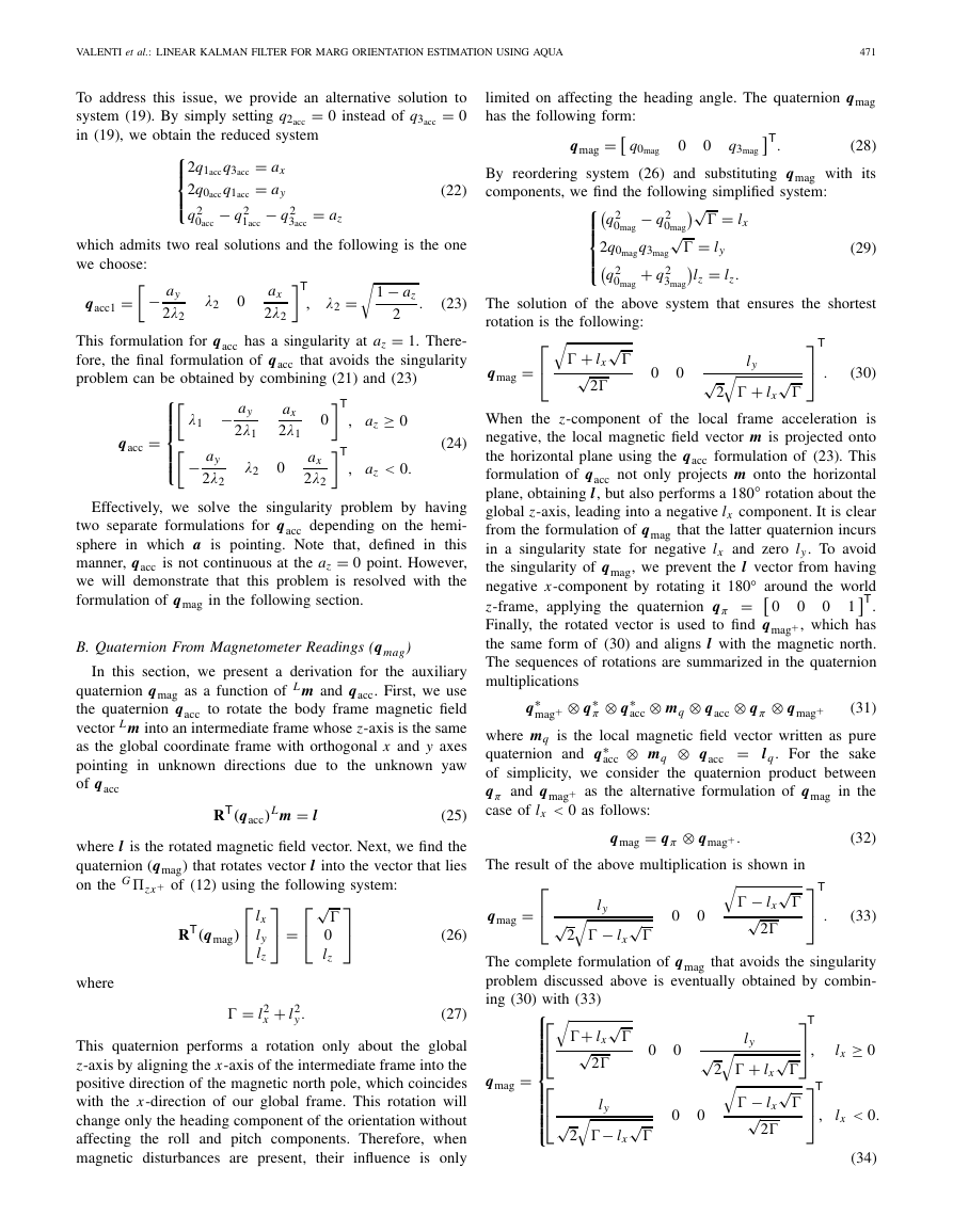
Fig. 1 shows the components of the quaternion orientation
during a simulated rotation with constant angular velocities
of 0.1 rad/s around the x-axis, −0.2 rad/s around the y-axis,
and 0.1 rad/s around the z-axis. We selected the noise of
the acceleration and magnetic field vectors to have standard
deviations of σa = 0.001 m/s2 and σm = 0.001 G for all the
three axes. Such angular velocity and noise standard deviation
values were chosen only for visualization purposes and any
other value would provide correct results as well. To obtain
the result in Fig. 1, we first assume that the acceleration is a
Gaussian random vector with mean μa = a and covariance
matrix �acc as summarized in the following:
L a = N
μa = a, �acc
(46)
�
VALENTI et al.: LINEAR KALMAN FILTER FOR MARG ORIENTATION ESTIMATION USING AQUA
473
Fig. 1. Quaternions components, mean and measurement, and the 3σ boundaries during a simulated rigid body rotation.
where a is the noise-free acceleration vector and �acc char-
acterizes the amount of noise we added in a to obtain L a.
Similarly, for the magnetic field vector
L m = N
μm = m, �mag
.
(47)
the quaternion L
G q,
As we saw in the previous section,
computed using algebraic quaternion algorithm (AQUA),
is a function of L a and L m through (24), (34), and (35).
G q = f (L a, L m). This value is what we
Thus, we can write L
call measurement. We approximate it as a normally distributed
random vector assuming that its mean directly derives from the
AQUA by processing the noise-free acceleration and magnetic
field vectors, while its uncertainty comes from the propagation
of the acceleration and magnetic field covariances (41) as
summarized in the following:
μ = f (a, m), �q = η
G q ≈ N
G q = f (L a, L m)], their mean, and the 3σ boundaries,
Finally, we plot the components of the quaternion measure-
ment [L
acknowledging that the standard deviations of the quaternion
components are the square root of the diagonal terms of the
covariance matrix �q. Using this procedure, we demonstrate
that the calculated boundaries properly enclose the quater-
nion measurement affected by the noise coming from the
sensors readings, propagated through the process explained
in Section III.
.
�acc, �mag
(48)
L
V. KALMAN FILTER DESIGN
In this section, we present the design of a novel quaternion-
based Kalman filter with a four-state vector (the quaternion
components) and linear process and measurements models.
The novel approach employs our external algorithm (AQUA)
to find the quaternion orientation of the rigid body as an
algebraic solution of a system using earth field data from a
MARG sensor. The computed quaternion is taken as mea-
surement for the Kalman filter to correct the predicted state
obtained by processing the readings provided by the angular
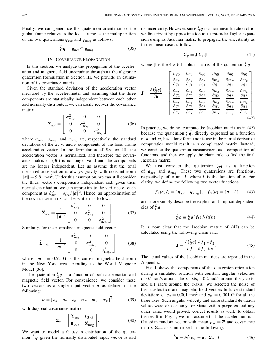
Fig. 2. Block diagram of the proposed quaternion-based Kalman filter for
MARG sensors.
rate sensor. Using this method, all the output equations are
linear, simplifying the design of the filter. Unlike other linear
quaternion-based filters previously proposed [9], [31], we do
not find the quaternion correction as output of an optimiza-
tion algorithm, but as an algebraic solution that ensures fast
convergence rate of the orientation estimation. The block
diagram of the proposed filter is shown in Fig. 2.
The orientation of a rigid body in space is determined by
the representation of the coordinate frame attached to the body
(the local frame L) with respect to the absolute coordinate
system (the global frame G). To simplify the calculations
in the following sections, we will refer to the orientation of
the global frame expressed with respect to the local frame.
The state vector of the proposed filter is composed of the
four quaternion components as follows:
xk+1 = L
G q = [q0 q1 q2 q3]T.
(49)
In this paper, we do not estimate the biases of the input
measurement vectors; however, a typical state augmentation
technique could be adopted to address this matter.
�
474
IEEE TRANSACTIONS ON INSTRUMENTATION AND MEASUREMENT, VOL. 65, NO. 2, FEBRUARY 2016
The initial quaternion estimate is given by the output of
the AQUA allowing a fast filter initialization in any starting
configuration.
A. Process Model
In the prediction step, the angular velocity vector, measured
by the triaxis gyroscope, is used to compute the first estimation
of the orientation in quaternion form. It is well known that the
rigid body angular motion obeys a vector differential equation
describing the rate of change of the orientation as quaternion
derivative [26]
˙qω,t
L
G
= − 1
2
L ω
q,t
⊗ L
G qt
.
(50)
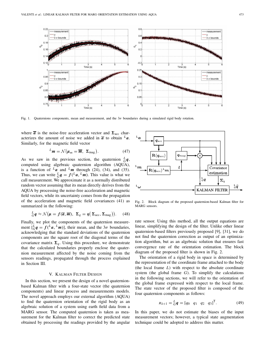
Final quaternion orientation of the global frame with respect to
Fig. 3.
◦
the local frame in a 180
rotation about the y-axis, found as quaternion
multiplication between qacc and qmag. The quaternion does not incur in
singularities, and as a result of the continuity test, it is continuous throughout
the rotation.
The above equation can be rewritten in matrix form as
shown in
B. Measurement Model
L
G
where
˙qω,t
= �(L ω)L
G qt
(51)
The measurement update step applies the quaternion
obtained from the AQUA analyzed in Section III. We can then
write
zk+1 = L
G qk+1
+ wzk+1
T
L ω
�(L ωt ) =
0
−L ω
×
the term [L ω×]
and, regardless of the time dependence,
denotes the cross-product matrix that is associated with L ω
and is equal to
−
t
L ω
(52)
t
t
[L ω×] =
⎡
⎣ 0
ωz
−ωy
−ωz
0
ωx
⎤
⎦.
ωy
−ωx
0
where wzk+1 is the measurement noise approximated as a white
Gaussian noise obtained from the propagation of the accelera-
tion and magnetic field measurement noises via the process
of Section III. Finally,
the measurement noise covariance
matrix Rk+1 will have the value previously found in the
covariance propagation part discussed in Section IV. Thus,
in terms of the measurement process, we can write
(53)
Rk+1 = �qk+1
(58)
(59)
The orientation of the global frame relative to the local
frame at time t can be computed by numerically integrating
the quaternion derivative using the sampling period �t. The
discrete state transition vector equation, which characterizes
the process model, is derived from (51) and is presented in
the following:
xk+1 = �(L ω, �t)xk + wk
(54)
where the state transition matrix is computed using a
zeroth-order integration
�(L ω, �t) ≈
�k(L ω)�t
I4×4 + 1
2
(55)
and
wk = − �t
2
�k vgk
= − �t
2
⎡
⎢⎢⎣
q2
q3
q1
−q0 −q3 −q2
q2 −q0 −q1
−q2
q1 −q0
⎤
⎥⎥⎦ vgk
(56)
where vgk is the white Gaussian measurement noise affecting
the gyroscope readings, with covariance matrix �g = σ 2
g I3×3.
Finally, the process noise covariance matrix Qk is equal to
Qk =
2
− �t
2
�k �g�k
T.
(57)
where �qk+1 is the covariance matrix computed in (41). In this
new approach, both process model and measurement model are
linear, and therefore the implementation of the proposed filter
uses the regular Kalman filter’s equations [37]. The estimated
state variables, which are the four quaternion components, are
related by the unit-norm constraint that is not preserved by the
Kalman filter equations. In order to preserve the quaternion
unit-norm property, the filter developed in this paper adopts
a final normalization step to normalize the estimate after the
measurement update stage.
The quaternion representing the orientation of the global
frame with respect to the local frame, calculated as per (35),
may have some discontinuities because the orientation can be
represented using two alternative rotation paths. When using
quaternions to represent the orientation, the alternative rotation
path is given by switching the sign of all the quaternion com-
ponents. This feature does not pose any problem in the orien-
tation representation. However, when the algebraic quaternion
is adopted in the correction step of an additive Kalman filter,
its value must be consistent with the current state. To resolve
this issue, we check the angular difference between the two
quantities,
in each updating step, by calculating their dot
product [38]. If the dot product is positive, we keep the
current quaternion measurement; otherwise, we use the nega-
tive quaternion, which represents the alternative rotation path.
Fig. 3 shows the final quaternion in a simulated 180° rotation
�


 2023年江西萍乡中考道德与法治真题及答案.doc
 2012年重庆南川中考生物真题及答案.doc
 2013年江西师范大学地理学综合及文艺理论基础考研真题.doc
 2020年四川甘孜小升初语文真题及答案I卷.doc
 2020年注册岩土工程师专业基础考试真题及答案.doc
 2023-2024学年福建省厦门市九年级上学期数学月考试题及答案.doc
 2021-2022学年辽宁省沈阳市大东区九年级上学期语文期末试题及答案.doc
 2022-2023学年北京东城区初三第一学期物理期末试卷及答案.doc
 2018上半年江西教师资格初中地理学科知识与教学能力真题及答案.doc
 2012年河北国家公务员申论考试真题及答案-省级.doc
 2020-2021学年江苏省扬州市江都区邵樊片九年级上学期数学第一次质量检测试题及答案.doc
 2022下半年黑龙江教师资格证中学综合素质真题及答案.doc