FANUC Series ot -MODEL D
FANUC Series ot Mate-MODEL D
•
•
CONNECTION MANUAL (HARDWARE)
B-64303EN/01
�
• No part of this manual may be reproduced in any form.
• All specifications and designs are subject to change without notice.
The products in this manual are controlled based on Japan's "Foreign Exchange and
Foreign Trade Law". The export from Japan may be subject to an export license by the
government of Japan.
Further, re-export to another country may be subject to the license of the government of
the country from where the product is re-exported. Furthermore, the product may also be
controlled by re-export regulations of the United States government.
Should you wish to export or re-export these products, please contact FANUC for advice .
In this manual we have tried as much as possible to describe all the various matters.
However, we cannot describe all the matters which must not be done, or which cannot be
done, because there are so many possibilities.
Therefore, matters which are not especially described as possible in this manual should be
recarded as "impossible".
'
J
�
B-64303EN/01
DEFINITION OF WARNING, CAUTION, AND NOTE
DEFINITION OF WARNING, CAUTION, AND NOTE
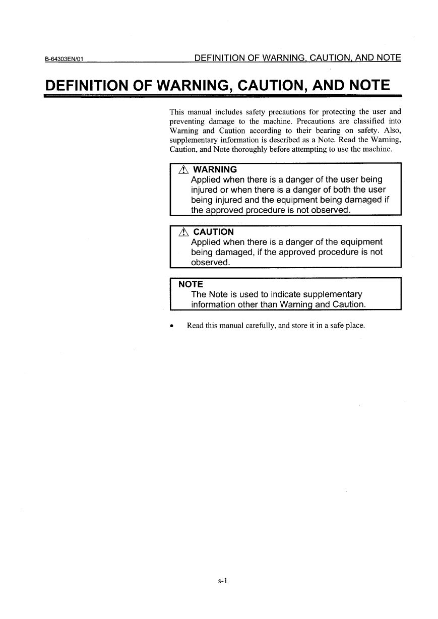
This manual includes safety precautions for protecting the user and
preventing damage to the machine. Precautions are classified into
Warning and Caution according to their bearing on safety. Also,
supplementary information is described as a Note. Read the Warning,
Caution, and Note thoroughly before attempting to use the machine .
& WARNING
Applied when there is a danger of the user being
injured or when there is a danger of both the user
being injured and the equipment being damaged if
the approved procedure is not observed.
& CAUTION
Applied when there is a danger of the equipment
being damaged, if the approved procedure is not
observed.
NOTE
The Note is used to indicate supplementary
information other than Warninq and Caution.
•
Read this manual carefully, and store it in a safe place.
s-1
�
�
B-64303EN/01
PREFACE
PREFACE
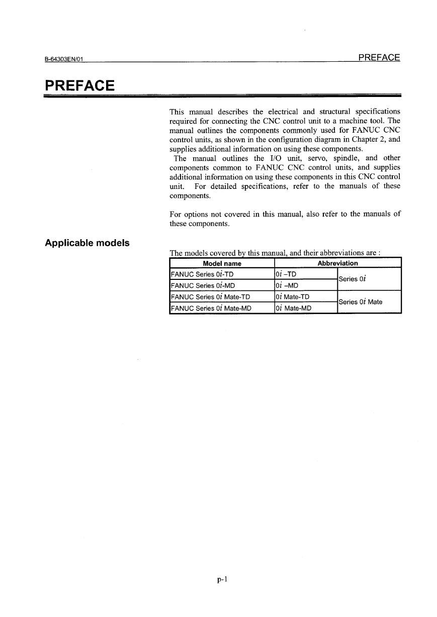
This manual describes the electrical and structural specifications
required for connecting the CNC control unit to a machine tool. The
manual outlines the components commonly used for FANUC CNC
control units, as shown in the configuration diagram in Chapter 2, and
supplies additional information on using these components.
The manual outlines
spindle, and other
components common to FANUC CNC control units, and supplies
additional information on using these components in this CNC control
unit.
to the manuals of these
components.
For detailed specifications,
the 1/0 unit,
servo,
refer
For options not covered in this manual, also refer to the manuals of
these components.
Applicable models
The mo e s covere
d I
db hi
rv t IS manua , an t err a
d hei
bb
reviations are :
Model name
FANUC Series Oi-TD
FANUC Series Oi-MD
FANUC Series oi Mate-TD
FANUC Series oi Male-MD
Abbreviation
Series oi
Series oi Mate
Oi-TD
oi -MD
oi Mate-TD
oi Male-MD
pol
�
PREFACE
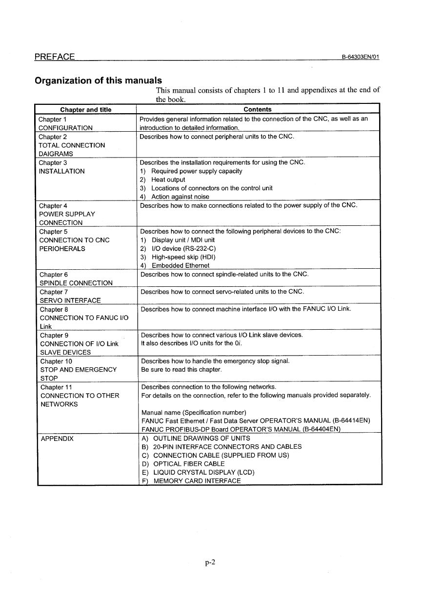
Organization of this manuals
B-64303EN /01
Chapter and title
Chapter 1
CONFIGURATION
Chapter 2
TOTAL CONNECTION
DAIGRAMS
Chapter 3
INSTALLATION
Chapter 4
POWER SUPPLAY
CONNECTION
Chapter 5
CONNECTION TO CNC
PERIOHERALS
Chapter 6
SPINDLE CONNECTION
Chapter 7
SERVO INTERFACE
Chapter 8
CONNECTION TO FANUC 1/0
Link
Chapter 9
CONNECTION OF 1/0 Link
SLAVE DEVICES
Chapter 10
STOP AND EMERGENCY
STOP
Chapter 11
CONNECTION TO OTHER
NETWORKS
APPENDIX
This manual consists of chapters 1 to 11 and appendixes at the end of
the book
Contents
Provides general information related to the connection of the CNC, as well as an
introduction to detailed information.
Describes how to connect peripheral units to the CNC.
Describes the installation requirements for using the CNC.
1) Required power supply capacity
2) Heat output
3) Locations of connectors on the control unit
4) Action aqainst noise
Describes how to make connections related to the power supply of the CNC.
Describes how to connect the following peripheral devices to the CNC:
1) Display unit I MDI unit
2) 1/0 device (RS-232-C)
3) High-speed skip (HDI)
4) Embedded Ethernet
Describes how to connect spindle-related units to the CNC.
Describes how to connect servo-related units to the CNC.
Describes how to connect machine interface 110 with the FANUC 110 Link.
Describes how to connect various 1/0 Link slave devices.
It also describes 1/0 units for the Oi.
Describes how to handle the emergency stop signal.
Be sure to read this chapter.
Describes connection to the following networks.
For details on the connection, refer to the following manuals provided separately.
Manual name (Specification number)
FANUC Fast Ethernet I Fast Data Server OPERATOR'S MANUAL (B-64414EN)
FANUC PROFIBUS-DP Board OPERATOR'S MANUAL (B-64404EN)
A) OUTLINE DRAWINGS OF UNITS
B) 20-PIN INTERFACE CONNECTORS AND CABLES
C) CONNECTION CABLE (SUPPLIED FROM US)
D) OPTICAL FIBER CABLE
E) LIQUID CRYSTAL DISPLAY (LCD)
F) MEMORY CARD INTERFACE
p-2
�
B-64303EN/01
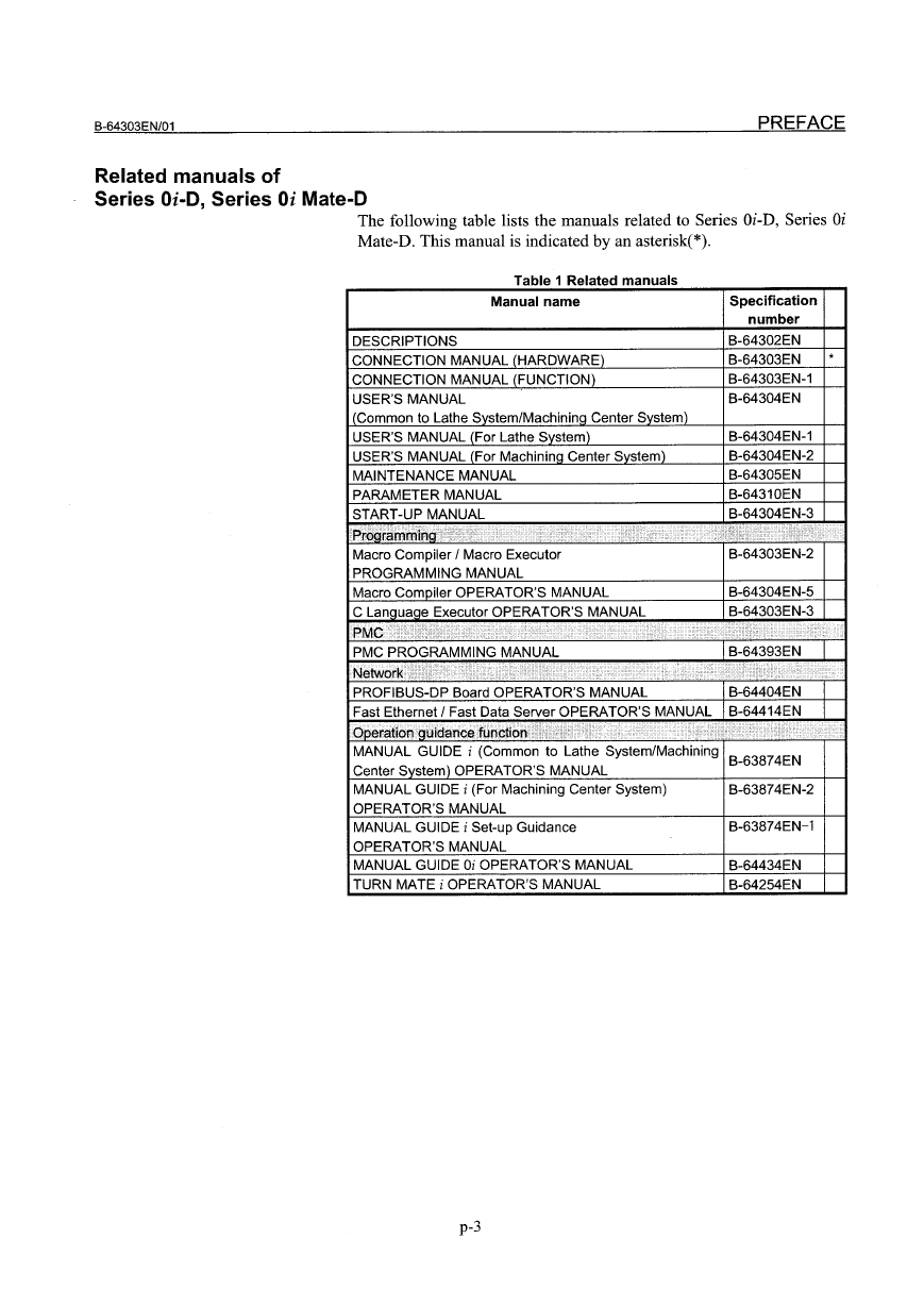
Related manuals of
Series Oi-O, Series Oi Mate-O
PREFACE
The followin g table lists the manuals related to Series Oi-D, Series Oi
Mate-D. This manual is indicated by an asterisk(*).
Table 1 Related manuals
Manual name
DESCRIPTIONS
CONNECTION MANUAL (HARDWARE)
CONNECTION MANUAL (FUNCTION)
USER'S MANUAL
(Common to Lathe Svstern/Machininq Center System)
USER'S MANUAL (For Lathe System)
USER'S MANUAL (For Machininq Center System)
MAINTENANCE MANUAL
PARAMETER MANUAL
START-UP MANUAL
Macro Compiler / Macro Executor
PROGRAMMING MANUAL
Macro Compiler OPERATOR'S MANUAL
~aqe Executor OPERATOR'S MANUAL
PMC PROGRAMM ING MANUAL
Specification
number
B-64302EN
B-64303EN
B-64303EN-1
B-64304EN
*
B-64304EN-1
B-64304EN-2
B-64305EN
B-64310EN
B-64304EN-3
B-64303EN-2
B-64304EN-5
Bii303EN-3
B-64393EN
PROFIBUS-DP Board OPERATOR 'S MANUAL
B-64404EN
Fast Ethernet / Fast Data Server OPERATOR'S MANUAL B-64414EN
,··.···i•..
::0
•••..'::: ::0::••••,. / .•':
:',01'11::::0':
MANUAL GUIDE i (Common to Lathe System/Machining
Center System) OPERATOR'S MANUAL
MANUAL GUIDE i (For Machining Center System)
OPERATOR'S MANUAL
MANUAL GUIDE i Set-up Guidance
OPERATOR 'S MANUAL
MANUAL GUIDE Oi OPERATOR 'S MANUAL
TURN MATE i OPERATOR 'S MANUAL
B-63874EN
B-63874EN-2
B-63874EN-l
B-64434EN
B-64254EN
p-3
�
PREFACE
B-64303EN/01
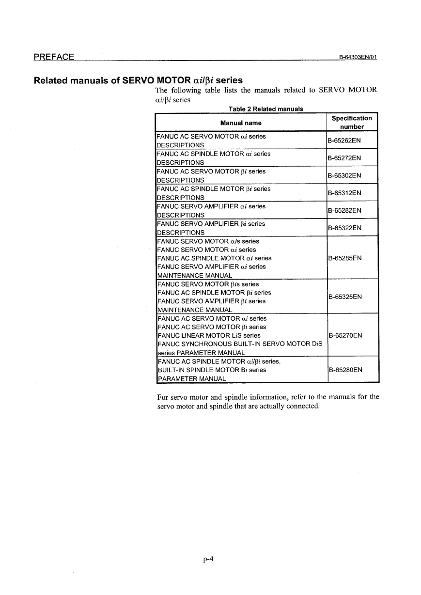
Related manuals of SERVO MOTOR ailf3i series
The following table lists the manuals related to SERVO MOTOR
ai/pi series
Table 2 Related manuals
Manual name
Specification
number
FANUC AC SERVO MOTOR ai series
DESCRIPTIONS
FANUC AC SPINDLE MOTOR ai series
DESCRIPTIONS
FANUC AC SERVO MOTOR Pi series
DESCRIPTIONS
FANUC AC SPINDLE MOTOR Pi series
DESCRIPTIONS
FANUC SERVO AMPLIFIER ai series
DESCRIPTIONS
FANUC SERVO AMPLIFIER Pi series
DESCRIPTIONS
FANUC SERVO MOTOR ais series
FANUC SERVO MOTOR ai series
FANUC AC SPINDLE MOTOR ai series
FANUC SERVO AMPLIFIER ai series
MAINTENANCE MANUAL
FANUC SERVO MOTOR Pis series
FANUC AC SPINDLE MOTOR Pi series
FANUC SERVO AMPLIFIER Pi series
MAINTENANCE MANUAL
FANUC AC SERVO MOTOR ai series
FANUC AC SERVO MOTOR Pi series
FANUC LINEAR MOTOR liS series
FANUC SYNCHRONOUS BUILT-IN SERVO MOTOR DiS
series PARAMETER MANUAL
FANUC AC SPINDLE MOTOR ai/pi series,
BUILT-IN SPINDLE MOTOR Bi series
PARAMETER MANUAL
B-65262EN
B-65272EN
B-65302EN
B-65312EN
B-65282EN
B-65322EN
B-65285EN
B-65325EN
B-65270EN
B-65280EN
For servo motor and spindle information , refer to the manuals for the
servo motor and spindle that are actually connected.
p-4
�



 2023年江西萍乡中考道德与法治真题及答案.doc
 2012年重庆南川中考生物真题及答案.doc
 2013年江西师范大学地理学综合及文艺理论基础考研真题.doc
 2020年四川甘孜小升初语文真题及答案I卷.doc
 2020年注册岩土工程师专业基础考试真题及答案.doc
 2023-2024学年福建省厦门市九年级上学期数学月考试题及答案.doc
 2021-2022学年辽宁省沈阳市大东区九年级上学期语文期末试题及答案.doc
 2022-2023学年北京东城区初三第一学期物理期末试卷及答案.doc
 2018上半年江西教师资格初中地理学科知识与教学能力真题及答案.doc
 2012年河北国家公务员申论考试真题及答案-省级.doc
 2020-2021学年江苏省扬州市江都区邵樊片九年级上学期数学第一次质量检测试题及答案.doc
 2022下半年黑龙江教师资格证中学综合素质真题及答案.doc