http://users.ece.gatech.edu/~rin ... handouts/spice3.pdf
http://hutchens.okstate.edu/ecen4303/chapters/chap4.pdf
实验 38 MOSFET 模型参数的提取
http://202.204.27.242/weidianzi/ ... %A8%CD%EA%A3%A9.doc
MOSFET 模型参数的提取
标记 LEVEL 指明选用级别。一级模型即常用的平方律特性描述的 Shichman-Hodges 模型,考虑了衬垫调制效率和沟道长度调制效应。二级模型考
虑了短沟、窄沟对阈电压的影响,迁移率随表面电场的变化,载流子极限速度引起的电流饱和和调制以及弱反型电流等二级效应,给出了完整的漏
电流表达式。三级模型是半经验模型,采用一些经验参数来描述类似于 MOS2 的二级效应。
MOS 管沟道长度较短时,需用二级模型。理论上,小于 8um 时,应有短沟等效应。实际上 5um 以下才需要二级模型。当短至 2um 以下,二级效
应复杂到难以解析表达时,启用三级模型。MOS 模型参数的提取一般需要计算机辅助才能进行。有两种实用方法,一是利用管子各工作区的特点,
分段线性拟合提取;二是直接拟合输出特性的优化提取。其中,直流参数的优化提取尚有不足之处:优化所获仅是拟合所需的特定参数,物理意义
不确,难以反馈指导工艺和结构的设计;只适合当前模型,模型稍做改动,要重新提取,不利于分段模型;对初值和权重的选取要求很高。
MOSFET 模型发展至今,已有五十多个模型。
下面简单介绍几个有代表性的模型:
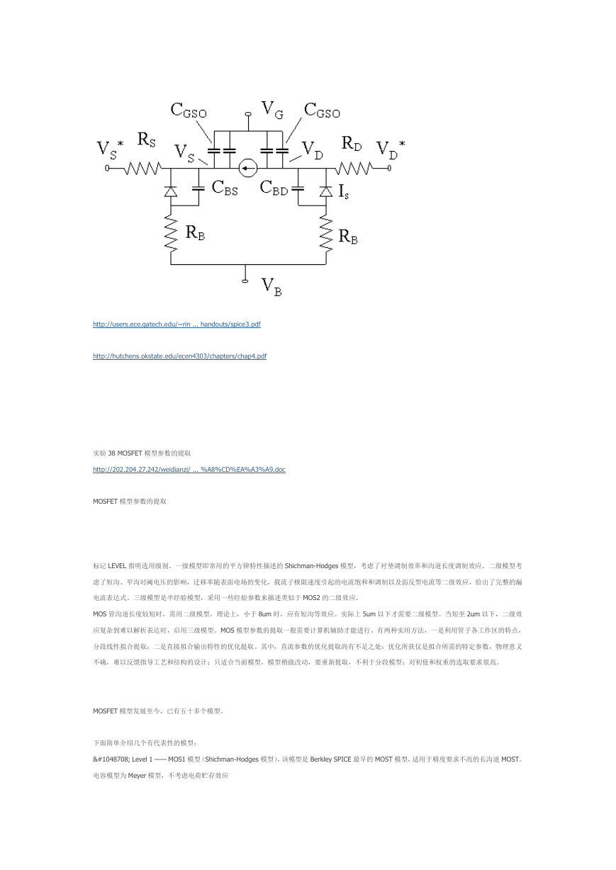
Level 1 —— MOS1 模型(Shichman-Hodges 模型),该模型是 Berkley SPICE 最早的 MOST 模型,适用于精度要求不高的长沟道 MOST。
电容模型为 Meyer 模型,不考虑电荷贮存效应
�
Level 2 —— MOS2 模型,该模型考虑了部分短沟道效应,电容模型为 Meyer 模型或 Ward-Dutton 模型。Ward-Dutton 模型考虑了电
荷贮存效应。
Level 3 —— MOS3 模型,为半经验模型,广泛用于数字电路设计中,适用于短沟道器件,对于沟道长度≥ 2μm 的器件所得模拟结果
很精确。
BSIM 模型—— Berkeley Short-Channel IGFET Model。BSIM 模型是专门为短沟道 MOST 而开发的模型。目前已经发展到 BSIM4 模型。
Level 4 —— BSIM1 模型, 适合于 L≈1μm,tox≈15nm 的 MOSFET。
BSIM1 模型考虑了小尺寸 MOST 的二阶效应包括
垂直电场对载流子迁移率的影响;
速度饱和效应;
DIBL(漏场感应势垒下降)效应;
电荷共享;
离子注入器件的杂质非均匀分布;
沟道长度调制效应;
亚阈值导电;
参数随几何尺寸的变化
HSPICE Level 28 —— 改进的 BSIM1 模型,适用于模拟电路设计,目前仍有广泛应用。
Level 39 —— BSIM2 模型,是在 BSIM1 的基础上开发出的深亚微米模型,它适用的沟道长度可小到 0.25μm,栅氧化层厚度可薄至
3.6nm。除了包括 BSIM1 的各种二级效应外,还考虑了以下效应:
漏/源区寄生电阻
热电子引起的输出电阻的下降
反型区电容效应
BSIM3 模型—— 由于 BSIM1 和 BSIM2 为解决精度,并考虑公式的简单化,引入了大量的经验参数,使模型参数过多并有冗余,用起
来比较麻烦。BSIM3 是基于准二维分析的物理模型,着重解决
器件工作的物理机制,并考虑器件尺寸和工艺参数的影响,力求使每个模型参数与器件特性的关系可预测,并设法减少模型参数的个数。
BSIM3 模型的特点:
它的参数是基于物理模型引入的,每个模型参数基本上都与器件某一方面的物理特性相对应。
BSIM3 模型目前应用最广泛的是 BSIM3v3(Level 49)
BSIM4 模型—— 2000 年发表的最新的 BSIM 模型,该模型在 BSIM3 模型的基础上做了一些针对射频(Radio Frequency)电路的改进,
不仅包括直流特性,还包括噪声模型以及外部寄生效应
MOS1 模型
�
模型参数:
KP——跨导
Xjl——横向扩散系数
L0——掩膜版上的几何沟道长度
L0 – Xjl= Leff 为有效沟道长度
W——沟道宽度
λ ——沟道长度调制系数
VT0——零偏阈电压(VBS=0)
γ ——衬偏调制系数
2ϕ
——表面反型电势
增加参数:
IS——衬底结饱和电流
这些参数中,KP 、VT0 、γ 、2ϕ
、IS 是电学类参数,在 SPICE2 中,可以直接确定它们的值,也可以通过几何、物理和工艺
参数计算而得。
几何、物理和工艺参数包括:
tP——一标志,对 N 沟为+1,对 P 沟为– 1
TPG—— 标志栅材料的类型,金属栅 TPG = 0;对多晶硅栅,掺杂与衬底相同时,TPG = –1 ;相反时,TPG = +1
ni——本征载流子浓度
εOX——氧化层介电常数
NSUB——衬底掺杂浓度
NSS——表面态密度
tOX——氧化层厚度
μ0——表面迁移率
JS——衬底结饱和电流密度
AD 和 AS——源扩散区和漏扩散区面积
进行电路模拟时,可以直接输入电学类参数,也可以输入几何、物理和工艺参数,通过公式计算得到电学类参数。如果都输入,那么
直接用电学类参数来模拟。
MOS2 模型考虑了小尺寸器件的一些二阶效应:
�
1) 沟道长度对阈电压的影响
2) 漏沟静电反馈效应对阈电压的影响
3) 沟道宽度对阈电压的影响
4) 迁移率随表面电场的变化
5) 沟道长度调制效应
6) 漏端速度饱和效应
7) 亚阈值导电
电容模型
1. PN 结电容
结电容由底部势垒电容和侧壁势垒电容两部分组成,引入的参数:
CJ(0)—— 单位底部面积零偏压时的结电容
CJSW(0)—— 单位侧壁长度零偏压时的结电容
AS,AD—— 分别为源结和漏结底部电容面积
PS,PD—— 分别为源结和漏结侧壁电容周长
mj—— 底部电容梯度因子
mjSW —— 侧壁电容梯度因子
ϕB—— 结电势
FC —— 正偏耗尽层电容公式中的系数公式参考相关手册。
栅电容
栅电容包括随偏压而变以及不随偏压而变两部分:
CGB = CGB +CGB CGS = CGS +CGS CGD = CGD +CGD
其中不随栅压改变的部分是源漏区覆盖电容以及栅与衬底间的交叠氧化层电容(在场氧化层上)
参数:
CGB0 ——单位沟道长度的栅-衬底覆盖电容
CGS0 ,CGD0 —— 单位沟道长度的栅源覆盖电容与栅漏覆盖电容
==========================================================================
模型参数的提取
电路模拟的精确度不仅与器件模型本身有关,还与给定的器件模型参数值是否正确有密切关系,因而器件模型参数的提取就成为电路
设计中的一个重要环节。
参数提取的任务:从一组器件测量特性中得到与器件模型相对应的一套器件模型参数值
参数提取的方法:
先给出一套模型参数初始值,代入器件模型公式得到一组模拟结果
比较模拟结果和测量特性,如二者不一致,就修改参数值,直到二者能很好地拟合
�
http://wlsyzx.yzu.edu.cn/kcwz/bdtqj/%E8%AF%BE%E4%BB%B6/4-6.pdf
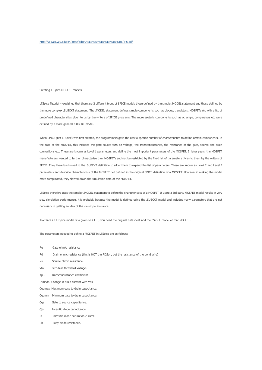
Creating LTSpice MOSFET models
LTSpice Tutorial 4 explained that there are 2 different types of SPICE model: those defined by the simple .MODEL statement and those defined by
the more complex .SUBCKT statement. The .MODEL statement defines simple components such as diodes, transistors, MOSFETs etc with a list of
predefined characteristics given to us by the writers of SPICE programs. The more esoteric components such as op amps, comparators etc were
defined by a more general .SUBCKT model.
When SPICE (not LTSpice) was first created, the programmers gave the user a specific number of characteristics to define certain components. In
the case of the MOSFET, this included the gate source turn on voltage, the transconductance, the resistance of the gate, source and drain
connections etc. These are known as Level 1 parameters and define the most important parameters of the MOSFET. In later years, the MOSFET
manufacturers wanted to further characterise their MOSFETs and not be restricted by the fixed list of parameters given to them by the writers of
SPICE. They therefore turned to the .SUBCKT definition to allow them to expand the list of parameters. These are known as Level 2 and Level 3
parameters and describe characteristics of the MOSFET not defined in the original SPICE definition of a MOSFET. However in making the model
more complicated, they slowed down the simulation time of the MOSFET.
LTSpice therefore uses the simpler .MODEL statement to define the characteristics of a MOSFET. If using a 3rd party MOSFET model results in very
slow simulation performance, it is probably because the model is defined using the .SUBCKT model and includes many parameters that are not
necessary in getting an idea of the circuit performance.
To create an LTSpice model of a given MOSFET, you need the original datasheet and the pSPICE model of that MOSFET.
The parameters needed to define a MOSFET in LTSpice are as follows:
Rg
Rd
Rs
Vto
Kp –
Gate ohmic resistance
Drain ohmic resistance (this is NOT the RDSon, but the resistance of the bond wire)
Source ohmic resistance.
Zero-bias threshold voltage.
Transconductance coefficient
Lambda Change in drain current with Vds
Cgdmax Maximum gate to drain capacitance.
Cgdmin Minimum gate to drain capacitance.
Cgs
Cjo
Is
Rb
Gate to source capacitance.
Parasitic diode capacitance.
Parasitic diode saturation current.
Body diode resistance.
�
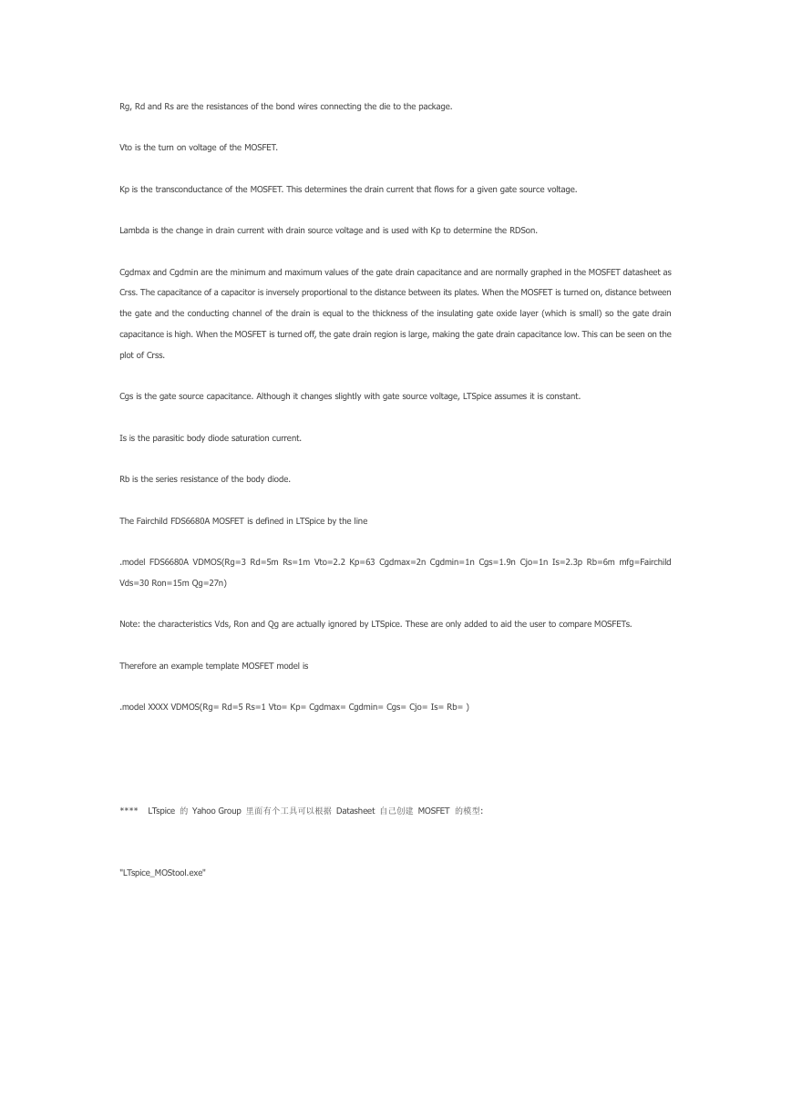
Rg, Rd and Rs are the resistances of the bond wires connecting the die to the package.
Vto is the turn on voltage of the MOSFET.
Kp is the transconductance of the MOSFET. This determines the drain current that flows for a given gate source voltage.
Lambda is the change in drain current with drain source voltage and is used with Kp to determine the RDSon.
Cgdmax and Cgdmin are the minimum and maximum values of the gate drain capacitance and are normally graphed in the MOSFET datasheet as
Crss. The capacitance of a capacitor is inversely proportional to the distance between its plates. When the MOSFET is turned on, distance between
the gate and the conducting channel of the drain is equal to the thickness of the insulating gate oxide layer (which is small) so the gate drain
capacitance is high. When the MOSFET is turned off, the gate drain region is large, making the gate drain capacitance low. This can be seen on the
plot of Crss.
Cgs is the gate source capacitance. Although it changes slightly with gate source voltage, LTSpice assumes it is constant.
Is is the parasitic body diode saturation current.
Rb is the series resistance of the body diode.
The Fairchild FDS6680A MOSFET is defined in LTSpice by the line
.model FDS6680A VDMOS(Rg=3 Rd=5m Rs=1m Vto=2.2 Kp=63 Cgdmax=2n Cgdmin=1n Cgs=1.9n Cjo=1n Is=2.3p Rb=6m mfg=Fairchild
Vds=30 Ron=15m Qg=27n)
Note: the characteristics Vds, Ron and Qg are actually ignored by LTSpice. These are only added to aid the user to compare MOSFETs.
Therefore an example template MOSFET model is
.model XXXX VDMOS(Rg= Rd=5 Rs=1 Vto= Kp= Cgdmax= Cgdmin= Cgs= Cjo= Is= Rb= )
****
LTspice 的 Yahoo Group 里面有个工具可以根据 Datasheet 自己创建 MOSFET 的模型:
"LTspice_MOStool.exe"
�


 2023年江西萍乡中考道德与法治真题及答案.doc
 2012年重庆南川中考生物真题及答案.doc
 2013年江西师范大学地理学综合及文艺理论基础考研真题.doc
 2020年四川甘孜小升初语文真题及答案I卷.doc
 2020年注册岩土工程师专业基础考试真题及答案.doc
 2023-2024学年福建省厦门市九年级上学期数学月考试题及答案.doc
 2021-2022学年辽宁省沈阳市大东区九年级上学期语文期末试题及答案.doc
 2022-2023学年北京东城区初三第一学期物理期末试卷及答案.doc
 2018上半年江西教师资格初中地理学科知识与教学能力真题及答案.doc
 2012年河北国家公务员申论考试真题及答案-省级.doc
 2020-2021学年江苏省扬州市江都区邵樊片九年级上学期数学第一次质量检测试题及答案.doc
 2022下半年黑龙江教师资格证中学综合素质真题及答案.doc