Disclaimer
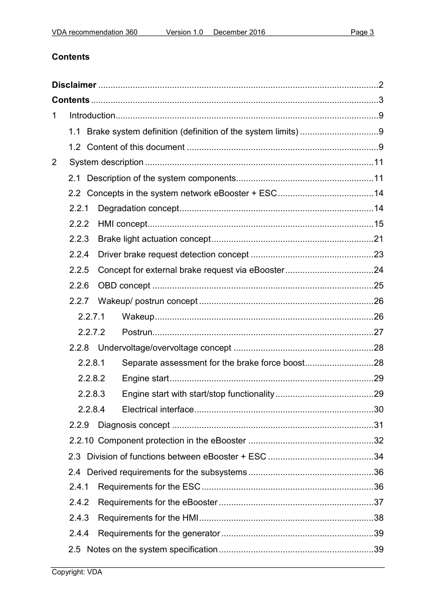
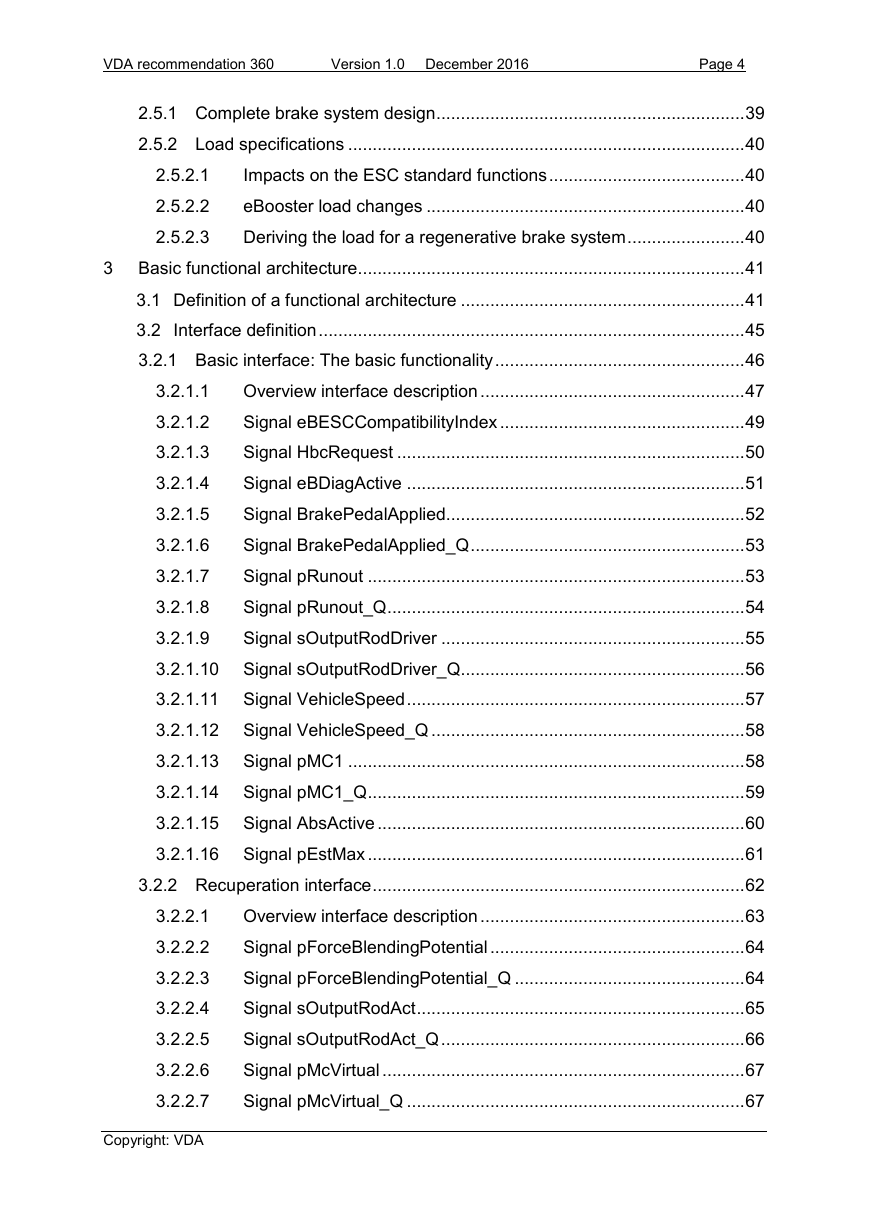
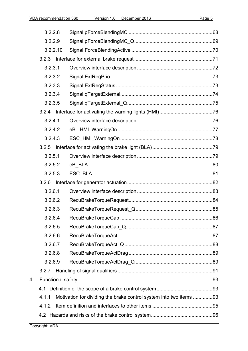
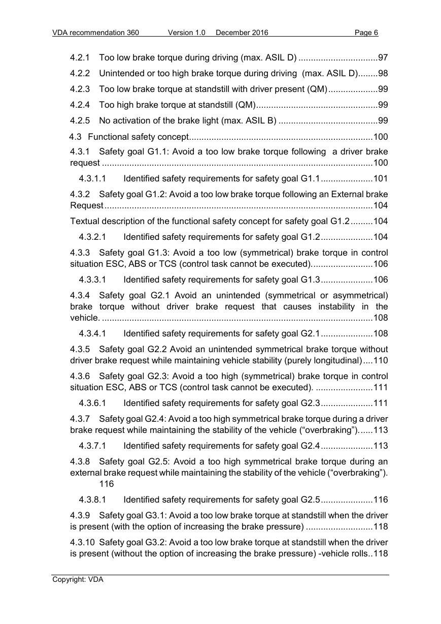
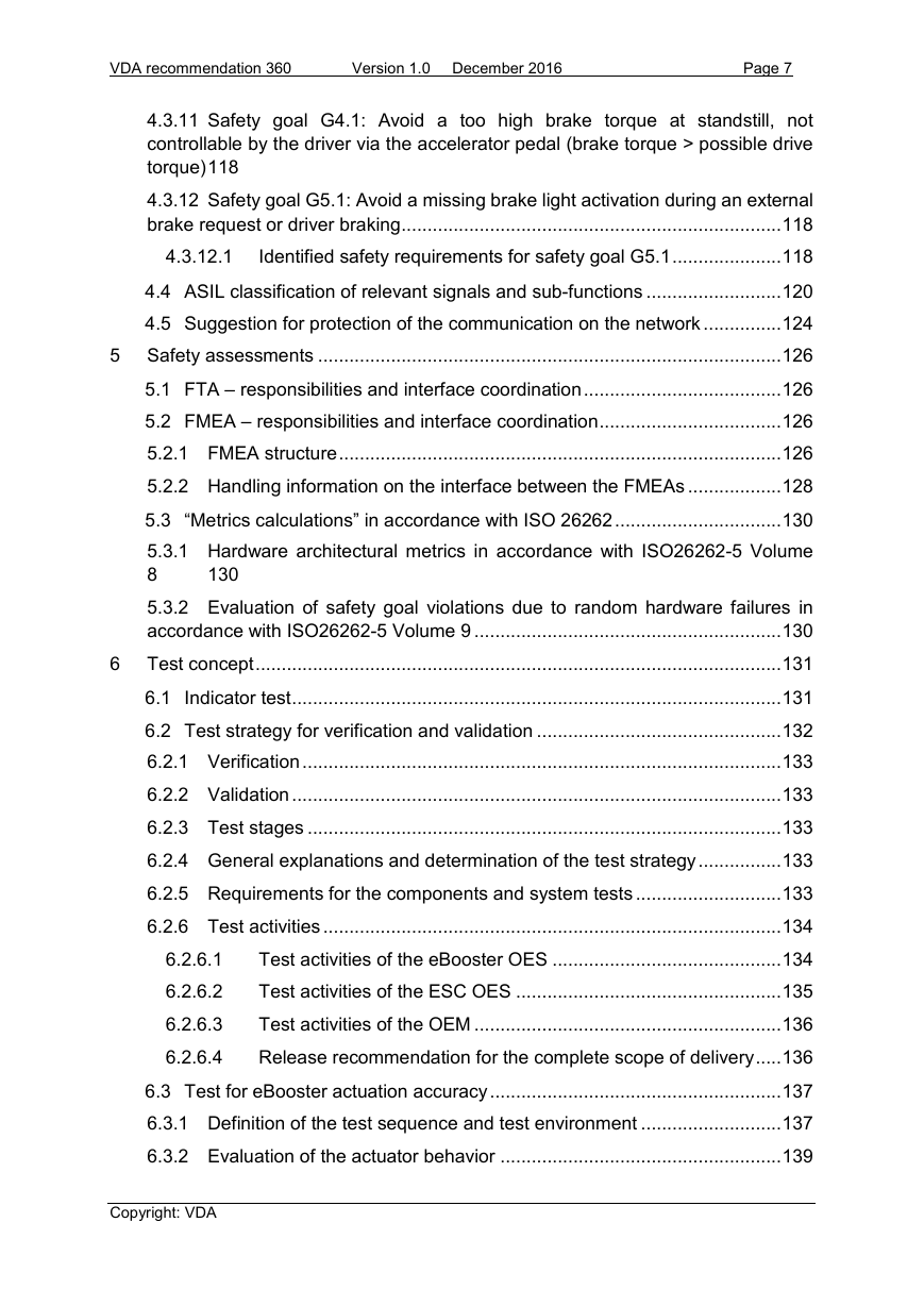
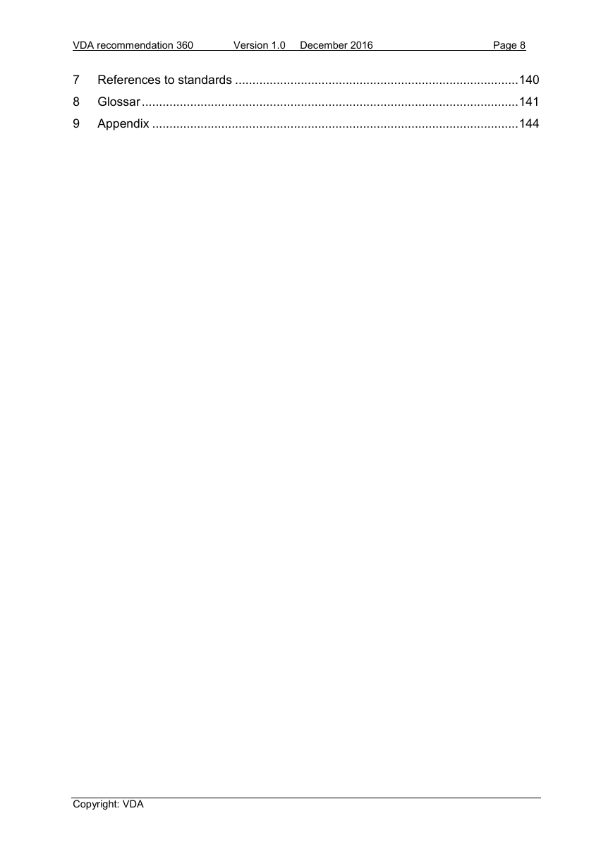
Contents
1 Introduction
1.1 Brake system definition (definition of the system limits)
1.2 Content of this document
2 System description
2.1 Description of the system components
2.2 Concepts in the system network eBooster + ESC
2.2.1 Degradation concept
2.2.2 HMI concept
2.2.3 Brake light actuation concept
2.2.4 Driver brake request detection concept
2.2.5 Concept for external brake request via eBooster
2.2.6 OBD concept
2.2.7 Wakeup/ postrun concept
2.2.7.1 Wakeup
2.2.7.2 Postrun
2.2.8 Undervoltage/overvoltage concept
2.2.8.1 Separate assessment for the brake force boost
2.2.8.2 Engine start
2.2.8.3 Engine start with start/stop functionality
2.2.8.4 Electrical interface
2.2.9 Diagnosis concept
2.2.10 Component protection in the eBooster
2.3 Division of functions between eBooster + ESC
2.4 Derived requirements for the subsystems
2.4.1 Requirements for the ESC
2.4.2 Requirements for the eBooster
2.4.3 Requirements for the HMI
2.4.4 Requirements for the generator
2.5 Notes on the system specification
2.5.1 Complete brake system design
2.5.2 Load specifications
2.5.2.1 Impacts on the ESC standard functions
2.5.2.2 eBooster load changes
2.5.2.3 Deriving the load for a regenerative brake system
3 Basic functional architecture
3.1 Definition of a functional architecture
3.2 Interface definition
3.2.1 Basic interface: The basic functionality
3.2.1.1 Overview interface description
3.2.1.2 Signal eBESCCompatibilityIndex
3.2.1.2.1 Signal specification
3.2.1.2.2 Signal requirements
3.2.1.3 Signal HbcRequest
3.2.1.3.1 Signal specification
3.2.1.3.2 Signal requirements
3.2.1.4 Signal eBDiagActive
3.2.1.4.1 Signal specification
3.2.1.4.2 Signal requirements
3.2.1.5 Signal BrakePedalApplied
3.2.1.5.1 Signal specification
3.2.1.5.2 Signal requirements
3.2.1.6 Signal BrakePedalApplied_Q
3.2.1.6.1 Signal specification
3.2.1.6.2 Signal requirements
3.2.1.7 Signal pRunout
3.2.1.7.1 Signal specification
3.2.1.7.2 Signal requirements
3.2.1.8 Signal pRunout_Q
3.2.1.8.1 Signal specification
3.2.1.8.2 Signal requirements
3.2.1.9 Signal sOutputRodDriver
3.2.1.9.1 Signal specification
3.2.1.9.2 Signal requirements
3.2.1.10 Signal sOutputRodDriver_Q
3.2.1.10.1 Signal specification
3.2.1.10.2 Signal requirements
3.2.1.11 Signal VehicleSpeed
3.2.1.11.1 Signal specification
3.2.1.11.2 Signal requirements
3.2.1.12 Signal VehicleSpeed_Q
3.2.1.12.1 Signal specification
3.2.1.12.2 Signal requirements
3.2.1.13 Signal pMC1
3.2.1.13.1 Signal specification
3.2.1.13.2 Signal requirements
3.2.1.14 Signal pMC1_Q
3.2.1.14.1 Signal specification
3.2.1.14.2 Signal requirements
3.2.1.15 Signal AbsActive
3.2.1.15.1 Signal specification
3.2.1.15.2 Signal requirements
3.2.1.16 Signal pEstMax
3.2.1.16.1 Signal specification
3.2.1.16.2 Signal requirements
3.2.2 Recuperation interface
3.2.2.1 Overview interface description
3.2.2.2 Signal pForceBlendingPotential
3.2.2.2.1 Signal specification
3.2.2.2.2 Signal requirements
3.2.2.3 Signal pForceBlendingPotential_Q
3.2.2.3.1 Signal specification
3.2.2.3.2 Signal requirements
3.2.2.4 Signal sOutputRodAct
3.2.2.4.1 Signal specification
3.2.2.4.2 Signal requirements
3.2.2.5 Signal sOutputRodAct_Q
3.2.2.5.1 Signal specification
3.2.2.5.2 Signal requirements
3.2.2.6 Signal pMcVirtual
3.2.2.6.1 Signal specification
3.2.2.6.2 Signal requirements
3.2.2.7 Signal pMcVirtual_Q
3.2.2.7.1 Signal specification
3.2.2.7.2 Signal requirements
3.2.2.8 Signal pForceBlendingMC
3.2.2.8.1 Signal specification
3.2.2.8.2 Signal requirements
3.2.2.9 Signal pForceBlendingMC_Q
3.2.2.9.1 Signal specification
3.2.2.9.2 Signal requirements
3.2.2.10 Signal ForceBlendingActive
3.2.2.10.1 Signal specification
3.2.2.10.2 Signal requirements
3.2.3 Interface for external brake request
3.2.3.1 Overview interface description
3.2.3.2 Signal ExtReqPrio
3.2.3.2.1 Signal specification
3.2.3.2.2 Signal requirements
3.2.3.3 Signal ExtReqStatus
3.2.3.3.1 Signal specification
3.2.3.3.2 Signal requirements
3.2.3.4 Signal qTargetExternal
3.2.3.4.1 Signal specification
3.2.3.4.2 Signal requirements
3.2.3.5 Signal qTargetExternal_Q
3.2.3.5.1 Signal specification
3.2.3.5.2 Signal requirements
3.2.4 Interface for activating the warning lights (HMI)
3.2.4.1 Overview interface description
3.2.4.2 eB_ HMI_WarningOn
3.2.4.2.1 Signal specification
3.2.4.2.2 Signal requirements
3.2.4.3 ESC_HMI_WarningOn
3.2.4.3.1 Signal specification
3.2.4.3.2 Signal requirements
3.2.5 Interface for activating the brake light (BLA)
3.2.5.1 Overview interface description
3.2.5.2 eB_BLA
3.2.5.2.1 Signal specification
3.2.5.2.2 Signal requirements
3.2.5.3 ESC_BLA
3.2.5.3.1 Signal specification
3.2.5.3.2 Signal requirements
3.2.6 Interface for generator actuation
3.2.6.1 Overview interface description
3.2.6.2 RecuBrakeTorqueRequest
3.2.6.2.1 Signal specification
3.2.6.2.2 Signal requirements
3.2.6.3 RecuBrakeTorqueRequest_Q
3.2.6.3.1 Signal specification
3.2.6.3.2 Signal requirements
3.2.6.4 RecuBrakeTorqueCap7F
3.2.6.4.1 Signal specification
3.2.6.4.2 Signal requirements
3.2.6.5 RecuBrakeTorqueCap_Q8F
3.2.6.5.1 Signal specification
3.2.6.5.2 Signal requirements
3.2.6.6 RecuBrakeTorqueAct
3.2.6.6.1 Signal specification
3.2.6.6.2 Signal requirements
3.2.6.7 RecuBrakeTorqueAct_Q
3.2.6.7.1 Signal specification
3.2.6.7.2 Signal requirements
3.2.6.8 RecuBrakeTorqueActDrag
3.2.6.8.1 Signal specification
3.2.6.8.2 Signal requirements
3.2.6.9 RecuBrakeTorqueActDrag_Q
3.2.6.9.1 Signal specification
3.2.6.9.2 Signal requirements
3.2.7 Handling of signal qualifiers
4 Functional safety
4.1 Definition of the scope of a brake control system
4.1.1 Motivation for dividing the brake control system into two items
4.1.2 Item definition and interfaces to other items
4.2 Hazards and risks of the brake control system
4.2.1 Too low brake torque during driving (max. ASIL D)
4.2.2 Unintended or too high brake torque during driving (max. ASIL D)
4.2.3 Too low brake torque at standstill with driver present (QM)
4.2.4 Too high brake torque at standstill (QM)
4.2.5 No activation of the brake light (max. ASIL B)
4.3 Functional safety concept
4.3.1 Safety goal G1.1: Avoid a too low brake torque following a driver brake request
4.3.1.1 Identified safety requirements for safety goal G1.1
4.3.2 Safety goal G1.2: Avoid a too low brake torque following an External brake Request
Textual description of the functional safety concept for safety goal G1.2
4.3.2.1 Identified safety requirements for safety goal G1.2
4.3.3 Safety goal G1.3: Avoid a too low (symmetrical) brake torque in control situation ESC, ABS or TCS (control task cannot be executed).
4.3.3.1 Identified safety requirements for safety goal G1.3
4.3.4 Safety goal G2.1 Avoid an unintended (symmetrical or asymmetrical) brake torque without driver brake request that causes instability in the vehicle.
4.3.4.1 Identified safety requirements for safety goal G2.1
4.3.5 Safety goal G2.2 Avoid an unintended symmetrical brake torque without driver brake request while maintaining vehicle stability (purely longitudinal)
4.3.6 Safety goal G2.3: Avoid a too high (symmetrical) brake torque in control situation ESC, ABS or TCS (control task cannot be executed).
4.3.6.1 Identified safety requirements for safety goal G2.3
4.3.7 Safety goal G2.4: Avoid a too high symmetrical brake torque during a driver brake request while maintaining the stability of the vehicle (“overbraking”).
4.3.7.1 Identified safety requirements for safety goal G2.4
4.3.8 Safety goal G2.5: Avoid a too high symmetrical brake torque during an external brake request while maintaining the stability of the vehicle (“overbraking”).
4.3.8.1 Identified safety requirements for safety goal G2.5
4.3.9 Safety goal G3.1: Avoid a too low brake torque at standstill when the driver is present (with the option of increasing the brake pressure)
4.3.10 Safety goal G3.2: Avoid a too low brake torque at standstill when the driver is present (without the option of increasing the brake pressure) -vehicle rolls
4.3.11 Safety goal G4.1: Avoid a too high brake torque at standstill, not controllable by the driver via the accelerator pedal (brake torque > possible drive torque)
4.3.12 Safety goal G5.1: Avoid a missing brake light activation during an external brake request or driver braking
4.3.12.1 Identified safety requirements for safety goal G5.1
4.4 ASIL classification of relevant signals and sub-functions
4.5 Suggestion for protection of the communication on the network
5 Safety assessments
5.1 FTA – responsibilities and interface coordination
5.2 FMEA – responsibilities and interface coordination
5.2.1 FMEA structure
5.2.2 Handling information on the interface between the FMEAs
5.3 “Metrics calculations” in accordance with ISO 26262
5.3.1 Hardware architectural metrics in accordance with ISO26262-5 Volume 8
5.3.2 Evaluation of safety goal violations due to random hardware failures in accordance with ISO26262-5 Volume 9
6 Test concept
6.1 Indicator test
6.2 Test strategy for verification and validation
6.2.1 Verification
6.2.2 Validation
6.2.3 Test stages
6.2.4 General explanations and determination of the test strategy
6.2.5 Requirements for the components and system tests
6.2.6 Test activities
6.2.6.1 Test activities of the eBooster OES
6.2.6.2 Test activities of the ESC OES
6.2.6.3 Test activities of the OEM
6.2.6.4 Release recommendation for the complete scope of delivery
6.3 Test for eBooster actuation accuracy
6.3.1 Definition of the test sequence and test environment
6.3.2 Evaluation of the actuator behavior
7 References to standards
8 Glossar
9 Appendix


 2023年江西萍乡中考道德与法治真题及答案.doc
 2012年重庆南川中考生物真题及答案.doc
 2013年江西师范大学地理学综合及文艺理论基础考研真题.doc
 2020年四川甘孜小升初语文真题及答案I卷.doc
 2020年注册岩土工程师专业基础考试真题及答案.doc
 2023-2024学年福建省厦门市九年级上学期数学月考试题及答案.doc
 2021-2022学年辽宁省沈阳市大东区九年级上学期语文期末试题及答案.doc
 2022-2023学年北京东城区初三第一学期物理期末试卷及答案.doc
 2018上半年江西教师资格初中地理学科知识与教学能力真题及答案.doc
 2012年河北国家公务员申论考试真题及答案-省级.doc
 2020-2021学年江苏省扬州市江都区邵樊片九年级上学期数学第一次质量检测试题及答案.doc
 2022下半年黑龙江教师资格证中学综合素质真题及答案.doc