MPC5604BRM_ReadMe_Rev8.2
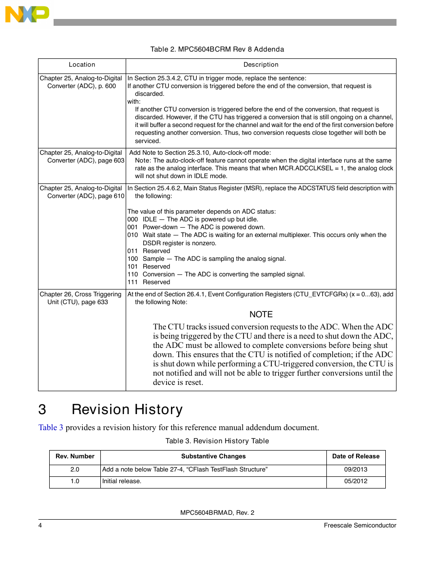
MPC5604BRMAD_rev2
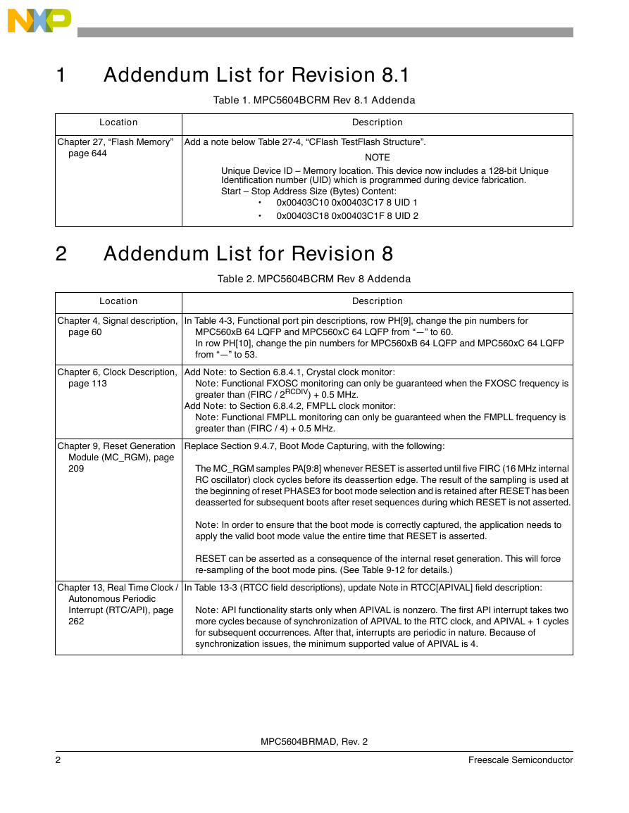
1 Addendum List for Revision 8.1
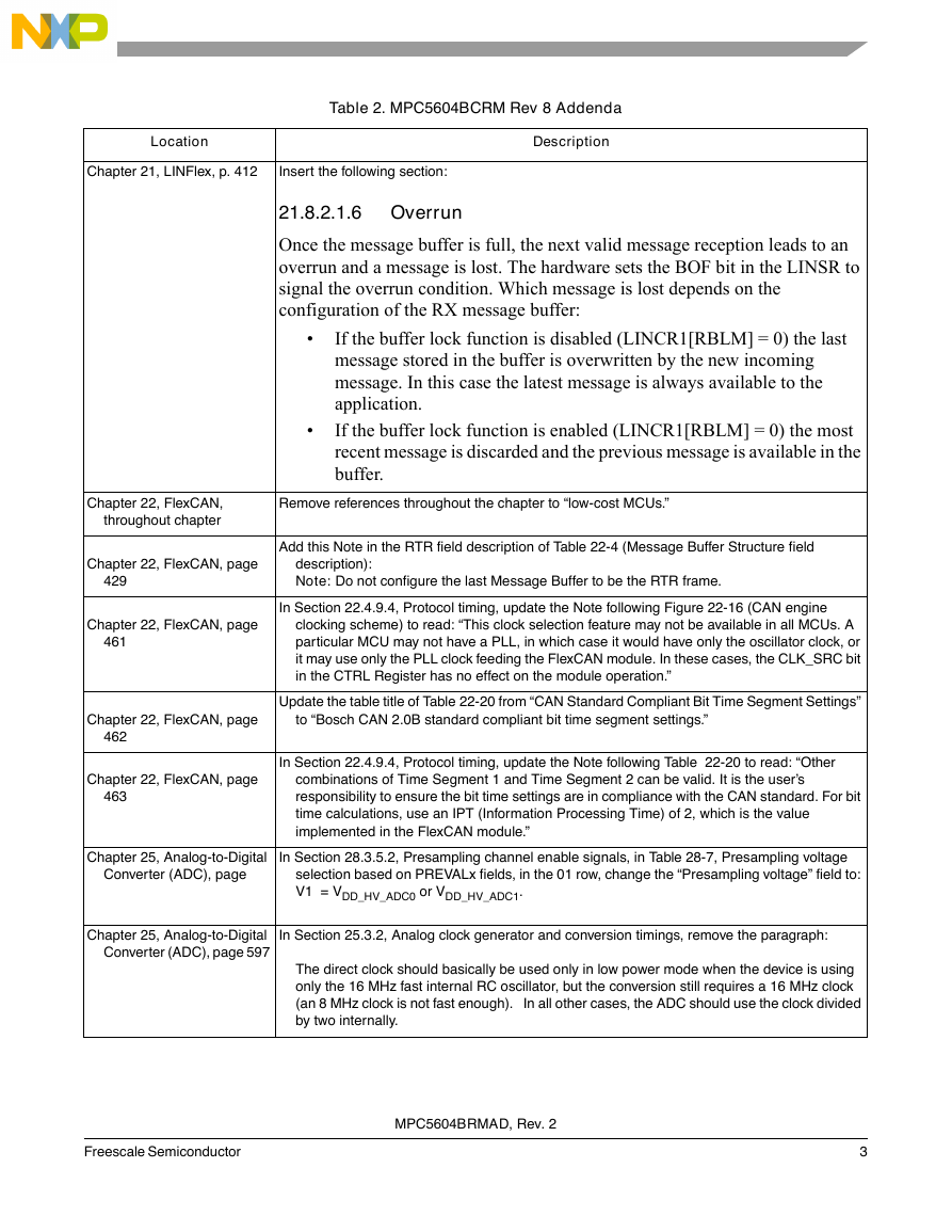
2 Addendum List for Revision 8
3 Revision History
MPC5604BCRM_rev8
Chapter 1 Preface
1.1 Overview
1.2 Audience
1.3 Guide to this reference manual
1.4 Register description conventions
1.5 References
1.6 How to use the MPC5604B documents
1.6.1 The MPC5604B document set
1.6.2 Reference manual content
1.7 Using the MPC5604B
1.7.1 Hardware design
1.7.2 Input/output pins
1.7.3 Software design
1.7.4 Other features
Chapter 2 Introduction
2.1 The MPC5604B microcontroller family
2.2 Features
2.2.1 MPC5604B family comparison
2.2.2 Block diagram
2.2.3 Chip-level features
2.3 Packages
2.4 Developer support
Chapter 3 Memory Map
Chapter 4 Signal description
4.1 Introduction
4.2 Package pinouts
4.3 Pad configuration during reset phases
4.4 Voltage supply pins
4.5 Pad types
4.6 System pins
4.7 Functional ports
4.8 Nexus 2+ pins
Chapter 5 Microcontroller Boot
5.1 Boot mechanism
5.1.1 Flash memory boot
5.1.1.1 Static mode
5.1.1.2 Alternate boot sectors
5.1.2 Serial boot mode
5.1.3 Censorship
5.1.3.1 Censorship password registers (NVPWD0 and NVPWD1)
5.1.3.2 Nonvolatile System Censorship Control registers (NVSCC0 and NVSCC1)
5.1.3.3 Censorship configuration
5.2 Boot Assist Module (BAM)
5.2.1 BAM software flow
5.2.1.1 BAM resources
5.2.1.2 Download and execute the new code
5.2.1.3 Censorship mode detection and serial password validation
5.2.1.3.1 Censorship disabled (private or public passwords):
5.2.1.3.2 Censorship enabled (private password)
5.2.1.4 Download start address, VLE bit and code size
5.2.1.5 Download data
5.2.1.6 Execute code
5.2.2 LINFlex (RS232) boot
5.2.2.1 Configuration
5.2.2.2 Protocol
5.2.3 FlexCAN boot
5.2.3.1 Configuration
5.2.3.2 Protocol
5.3 System Status and Configuration Module (SSCM)
5.3.1 Introduction
5.3.2 Features
5.3.3 Modes of operation
5.3.4 Memory map and register description
5.3.4.1 System Status Register (SSCM_STATUS)
5.3.4.2 System Memory Configuration Register (SSCM_MEMCONFIG)
5.3.4.3 Error Configuration (SSCM_ERROR)
5.3.4.4 Debug Status Port Register (SSCM_DEBUGPORT)
5.3.4.5 Password comparison registers
--- Clocks and power ---
Chapter 6 Clock Description
6.1 Clock architecture
6.2 Clock gating
6.3 Fast external crystal oscillator (FXOSC) digital interface
6.3.1 Main features
6.3.2 Functional description
6.3.3 Register description
6.4 Slow external crystal oscillator (SXOSC) digital interface
6.4.1 Introduction
6.4.2 Main features
6.4.3 Functional description
6.4.4 Register description
6.5 Slow internal RC oscillator (SIRC) digital interface
6.5.1 Introduction
6.5.2 Functional description
6.5.3 Register description
6.6 Fast internal RC oscillator (FIRC) digital interface
6.6.1 Introduction
6.6.2 Functional description
6.6.3 Register description
6.7 Frequency-modulated phase-locked loop (FMPLL)
6.7.1 Introduction
6.7.2 Overview
6.7.3 Features
6.7.4 Memory map
6.7.5 Register description
6.7.5.1 Control Register (CR)
6.7.5.2 Modulation Register (MR)
6.7.6 Functional description
6.7.6.1 Normal mode
6.7.6.2 Progressive clock switching
6.7.6.3 Normal mode with frequency modulation
6.7.6.4 Powerdown mode
6.7.7 Recommendations
6.8 Clock monitor unit (CMU)
6.8.1 Introduction
6.8.2 Main features
6.8.3 Block diagram
6.8.4 Functional description
6.8.4.1 Crystal clock monitor
6.8.4.2 FMPLL clock monitor
6.8.4.3 Frequency meter
6.8.5 Memory map and register description
6.8.5.1 Control Status Register (CMU_CSR)
6.8.5.2 Frequency Display Register (CMU_FDR)
6.8.5.3 High Frequency Reference Register FMPLL (CMU_HFREFR)
6.8.5.4 Low Frequency Reference Register FMPLL (CMU_LFREFR)
6.8.5.5 Interrupt Status Register (CMU_ISR)
6.8.5.6 Measurement Duration Register (CMU_MDR)
Chapter 7 Clock Generation Module (MC_CGM)
7.1 Overview
7.2 Features
7.3 Modes of Operation
7.3.1 Normal and Reset Modes of Operation
7.4 External Signal Description
7.5 Memory Map and Register Definition
7.5.1 Register Descriptions
7.5.1.1 Output Clock Enable Register (CGM_OC_EN)
7.5.1.2 Output Clock Division Select Register (CGM_OCDS_SC)
7.5.1.3 System Clock Select Status Register (CGM_SC_SS)
7.5.1.4 System Clock Divider Configuration Registers (CGM_SC_DC0…2)
7.6 Functional Description
7.6.1 System Clock Generation
7.6.1.1 System Clock Source Selection
7.6.1.2 System Clock Disable
7.6.1.3 System Clock Dividers
7.6.1.4 Dividers Functional Description
7.6.2 Output Clock Multiplexing
7.6.3 Output Clock Division Selection
Chapter 8 Mode Entry Module (MC_ME)
8.1 Introduction
8.1.1 Overview
8.1.2 Features
8.1.3 Modes of Operation
8.2 External Signal Description
8.3 Memory Map and Register Definition
8.3.1 Register Description
8.3.1.1 Global Status Register (ME_GS)
8.3.1.2 Mode Control Register (ME_MCTL)
8.3.1.3 Mode Enable Register (ME_ME)
8.3.1.4 Interrupt Status Register (ME_IS)
8.3.1.5 Interrupt Mask Register (ME_IM)
8.3.1.6 Invalid Mode Transition Status Register (ME_IMTS)
8.3.1.7 Debug Mode Transition Status Register (ME_DMTS)
8.3.1.8 RESET Mode Configuration Register (ME_RESET_MC)
8.3.1.9 TEST Mode Configuration Register (ME_TEST_MC)
8.3.1.10 SAFE Mode Configuration Register (ME_SAFE_MC)
8.3.1.11 DRUN Mode Configuration Register (ME_DRUN_MC)
8.3.1.12 RUN0…3 Mode Configuration Registers (ME_RUN0…3_MC)
8.3.1.13 HALT Mode Configuration Register (ME_HALT_MC)
8.3.1.14 STOP Mode Configuration Register (ME_STOP_MC)
8.3.1.15 STANDBY Mode Configuration Register (ME_STANDBY_MC)
8.3.1.16 Peripheral Status Register 0 (ME_PS0)
8.3.1.17 Peripheral Status Register 1 (ME_PS1)
8.3.1.18 Peripheral Status Register 2 (ME_PS2)
8.3.1.19 Peripheral Status Register 3 (ME_PS3)
8.3.1.20 Run Peripheral Configuration Registers (ME_RUN_PC0…7)
8.3.1.21 Low-Power Peripheral Configuration Registers (ME_LP_PC0…7)
8.3.1.22 Peripheral Control Registers (ME_PCTL0…143)
8.4 Functional Description
8.4.1 Mode Transition Request
8.4.2 Modes Details
8.4.2.1 RESET Mode
8.4.2.2 DRUN Mode
8.4.2.3 SAFE Mode
8.4.2.4 TEST Mode
8.4.2.5 RUN0…3 Modes
8.4.2.6 HALT Mode
8.4.2.7 STOP Mode
8.4.2.8 STANDBY Mode
8.4.3 Mode Transition Process
8.4.3.1 Target Mode Request
8.4.3.2 Target Mode Configuration Loading
8.4.3.3 Peripheral Clocks Disable
8.4.3.4 Processor Low-Power Mode Entry
8.4.3.5 Processor and System Memory Clock Disable
8.4.3.6 Clock Sources Switch-On
8.4.3.7 Main Voltage Regulator Switch-On
8.4.3.8 Flash Modules Switch-On
8.4.3.9 FMPLL Switch-On
8.4.3.10 Power Domain #2 Switch-On
8.4.3.11 Pad Outputs-On
8.4.3.12 Peripheral Clocks Enable
8.4.3.13 Processor and Memory Clock Enable
8.4.3.14 Processor Low-Power Mode Exit
8.4.3.15 System Clock Switching
8.4.3.16 Power Domain #2 Switch-Off
8.4.3.17 Pad Switch-Off
8.4.3.18 FMPLL Switch-Off
8.4.3.19 Clock Sources Switch-Off
8.4.3.20 Flash Switch-Off
8.4.3.21 Main Voltage Regulator Switch-Off
8.4.3.22 Current Mode Update
8.4.4 Protection of Mode Configuration Registers
8.4.5 Mode Transition Interrupts
8.4.5.1 Invalid Mode Configuration Interrupt
8.4.5.2 Invalid Mode Transition Interrupt
8.4.5.3 SAFE Mode Transition Interrupt
8.4.5.4 Mode Transition Complete interrupt
8.4.6 Peripheral Clock Gating
8.4.7 Application Example
Chapter 9 Reset Generation Module (MC_RGM)
9.1 Introduction
9.1.1 Overview
9.1.2 Features
9.1.3 Modes of operation
9.2 External signal description
9.3 Memory map and register definition
9.3.1 Register descriptions
9.3.1.1 Functional Event Status Register (RGM_FES)
9.3.1.2 Destructive Event Status Register (RGM_DES)
9.3.1.3 Functional Event Reset Disable Register (RGM_FERD)
9.3.1.4 Destructive Event Reset Disable Register (RGM_DERD)
9.3.1.5 Functional Event Alternate Request Register (RGM_FEAR)
9.3.1.6 Destructive Event Alternate Request Register (RGM_DEAR)
9.3.1.7 Functional Event Short Sequence Register (RGM_FESS)
9.3.1.8 STANDBY Reset Sequence Register (RGM_STDBY)
9.3.1.9 Functional Bidirectional Reset Enable Register (RGM_FBRE)
9.4 Functional Description
9.4.1 Reset State Machine
9.4.1.1 PHASE0 Phase
9.4.1.2 PHASE1 Phase
9.4.1.3 PHASE2 Phase
9.4.1.4 PHASE3 Phase
9.4.1.5 IDLE Phase
9.4.2 Destructive Resets
9.4.3 External Reset
9.4.4 Functional Resets
9.4.5 STANDBY Entry Sequence
9.4.6 Alternate Event Generation
9.4.7 Boot Mode Capturing
Chapter 10 Power Control Unit (MC_PCU)
10.1 Introduction
10.1.1 Overview
10.1.2 Features
10.1.3 Modes of Operation
10.2 External Signal Description
10.3 Memory Map and Register Definition
10.3.1 Register Descriptions
10.3.1.1 Power Domain #0 Configuration Register (PCU_PCONF0)
10.3.1.2 Power Domain #1 Configuration Register (PCU_PCONF1)
10.3.1.3 Power Domain #2 Configuration Register (PCU_PCONF2)
10.3.1.4 Power Domain Status Register (PCU_PSTAT)
10.4 Functional Description
10.4.1 General
10.4.2 Reset / Power-On Reset
10.4.3 MC_PCU Configuration
10.4.4 Mode Transitions
10.4.4.1 DRUN, SAFE, TEST, RUN0…3, HALT, and STOP Mode Transition
10.4.4.2 STANDBY Mode Transition
10.4.4.3 Power Saving for Memories During STANDBY Mode
10.5 Initialization Information
10.6 Application Information
10.6.1 STANDBY Mode Considerations
Chapter 11 Voltage Regulators and Power Supplies
11.1 Voltage regulators
11.1.1 High power regulator (HPREG)
11.1.2 Low power regulator (LPREG)
11.1.3 Ultra low power regulator (ULPREG)
11.1.4 LVDs and POR
11.1.5 VREG digital interface
11.1.6 Register description
11.2 Power supply strategy
11.3 Power domain organization
Chapter 12 Wakeup Unit (WKPU)
12.1 Overview
12.2 Features
12.3 External signal description
12.4 Memory map and register description
12.4.1 Memory map
12.4.2 NMI Status Flag Register (NSR)
12.4.3 NMI Configuration Register (NCR)
12.4.4 Wakeup/Interrupt Status Flag Register (WISR)
12.4.5 Interrupt Request Enable Register (IRER)
12.4.6 Wakeup Request Enable Register (WRER)
12.4.7 Wakeup/Interrupt Rising-Edge Event Enable Register (WIREER)
12.4.8 Wakeup/Interrupt Falling-Edge Event Enable Register (WIFEER)
12.4.9 Wakeup/Interrupt Filter Enable Register (WIFER)
12.4.10 Wakeup/Interrupt Pullup Enable Register (WIPUER)
12.5 Functional description
12.5.1 General
12.5.2 Non-maskable interrupts
12.5.2.1 NMI management
12.5.3 External wakeups/interrupts
12.5.3.1 External interrupt management
12.5.4 On-chip wakeups
12.5.4.1 On-chip wakeup management
Chapter 13 Real Time Clock / Autonomous Periodic Interrupt (RTC/API)
13.1 Overview
13.2 Features
13.3 Device-specific information
13.4 Modes of operation
13.4.1 Functional mode
13.4.2 Debug mode
13.5 Register descriptions
13.5.1 RTC Supervisor Control Register (RTCSUPV)
13.5.2 RTC Control Register (RTCC)
13.5.3 RTC Status Register (RTCS)
13.5.4 RTC Counter Register (RTCCNT)
13.6 RTC functional description
13.7 API functional description
Chapter 14 CAN Sampler
14.1 Introduction
14.2 Main features
14.3 Register description
14.3.1 Control Register (CR)
14.3.2 Sample register n (n = 0..11)
14.4 Functional description
14.4.1 Enabling/Disabling the CAN sampler
14.4.2 Baud rate generation
--- Core platform modules ---
Chapter 15 e200z0h Core
15.1 Overview
15.2 Microarchitecture summary
15.3 Block diagram
15.4 Features
15.4.1 Instruction unit features
15.4.2 Integer unit features
15.4.3 Load/Store unit features
15.4.4 e200z0h system bus features
15.4.5 Nexus 2+ features
15.5 Core registers and programmer’s model
Chapter 16 Interrupt Controller (INTC)
16.1 Introduction
16.2 Features
16.3 Block diagram
16.4 Modes of operation
16.4.1 Normal mode
16.4.1.1 Software vector mode
16.4.1.2 Hardware vector mode
16.4.1.3 Debug mode
16.4.1.4 Stop mode
16.5 Memory map and register description
16.5.1 Module memory map
16.5.2 Register description
16.5.2.1 INTC Module Configuration Register (INTC_MCR)
16.5.2.2 INTC Current Priority Register for Processor (INTC_CPR)
16.5.2.3 INTC Interrupt Acknowledge Register (INTC_IACKR)
16.5.2.4 INTC End-of-Interrupt Register (INTC_EOIR)
16.5.2.5 INTC Software Set/Clear Interrupt Registers (INTC_SSCIR0_3-INTC_SSCIR4_7)
16.5.2.6 INTC Priority Select Registers (INTC_PSR0_3-INTC_PSR208_210)
16.6 Functional description
16.6.1 Interrupt request sources
16.6.1.1 Peripheral interrupt requests
16.6.1.2 Software configurable interrupt requests
16.6.1.3 Unique vector for each interrupt request source
16.6.2 Priority management
16.6.2.1 Current priority and preemption
16.6.2.1.1 Priority arbitrator subblock
16.6.2.1.2 Request selector subblock
16.6.2.1.3 Vector encoder subblock
16.6.2.1.4 Priority Comparator subblock
16.6.2.2 Last-In First-Out (LIFO)
16.6.3 Handshaking with processor
16.6.3.1 Software vector mode handshaking
16.6.3.1.1 Acknowledging interrupt request to processor
16.6.3.1.2 End of interrupt exception handler
16.6.3.2 Hardware vector mode handshaking
16.7 Initialization/application information
16.7.1 Initialization flow
16.7.2 Interrupt exception handler
16.7.2.1 Software vector mode
16.7.2.2 Hardware vector mode
16.7.3 ISR, RTOS, and task hierarchy
16.7.4 Order of execution
16.7.5 Priority ceiling protocol
16.7.5.1 Elevating priority
16.7.5.2 Ensuring coherency
16.7.6 Selecting priorities according to request rates and deadlines
16.7.7 Software configurable interrupt requests
16.7.7.1 Scheduling a lower priority portion of an ISR
16.7.7.2 Scheduling an ISR on another processor
16.7.8 Lowering priority within an ISR
16.7.9 Negating an interrupt request outside of its ISR
16.7.9.1 Negating an interrupt request as a side effect of an ISR
16.7.9.2 Negating multiple interrupt requests in one ISR
16.7.9.3 Proper setting of interrupt request priority
16.7.10 Examining LIFO contents
Chapter 17 Crossbar Switch (XBAR)
17.1 Introduction
17.2 Block diagram
17.3 Overview
17.4 Features
17.5 Modes of operation
17.5.1 Normal mode
17.5.2 Debug mode
17.6 Functional description
17.6.1 Overview
17.6.2 General operation
17.6.3 Master ports
17.6.4 Slave ports
17.6.5 Priority assignment
17.6.6 Arbitration
17.6.6.1 Fixed priority operation
17.6.6.1.1 Parking
Chapter 18 Memory Protection Unit (MPU)
18.1 Introduction
18.2 Features
18.3 Modes of operation
18.4 External signal description
18.5 Memory map and register description
18.5.1 Memory map
18.5.2 Register description
18.5.2.1 MPU Control/Error Status Register (MPU_CESR)
18.5.2.2 MPU Error Address Register, Slave Port n (MPU_EARn)
18.5.2.3 MPU Error Detail Register, Slave Port n (MPU_EDRn)
18.5.2.4 MPU Region Descriptor n (MPU_RGDn)
18.5.2.4.1 MPU Region Descriptor n, Word 0 (MPU_RGDn.Word0)
18.5.2.4.2 MPU Region Descriptor n, Word 1 (MPU_RGDn.Word1)
18.5.2.4.3 MPU Region Descriptor n, Word 2 (MPU_RGDn.Word2)
18.5.2.4.4 MPU Region Descriptor n, Word 3 (MPU_RGDn.Word3)
18.5.2.5 MPU Region Descriptor Alternate Access Control n (MPU_RGDAACn)
18.6 Functional description
18.6.1 Access evaluation macro
18.6.1.1 Access evaluation - Hit determination
18.6.1.2 Access evaluation - Privilege violation determination
18.6.2 Putting it all together and AHB error terminations
18.7 Initialization information
18.8 Application information
Chapter 19 System Integration Unit Lite (SIUL)
19.1 Introduction
19.2 Overview
19.3 Features
19.4 External signal description
19.4.1 Detailed signal descriptions
19.4.1.1 General-purpose I/O pins (GPIO[0:122])
19.4.1.2 External interrupt request input pins (EIRQ[0:15])
19.5 Memory map and register description
19.5.1 SIUL memory map
19.5.2 Register protection
19.5.3 Register descriptions
19.5.3.1 MCU ID Register #1 (MIDR1)
19.5.3.2 MCU ID Register #2 (MIDR2)
19.5.3.3 Interrupt Status Flag Register (ISR)
19.5.3.4 Interrupt Request Enable Register (IRER)
19.5.3.5 Interrupt Rising-Edge Event Enable Register (IREER)
19.5.3.6 Interrupt Falling-Edge Event Enable Register (IFEER)
19.5.3.7 Interrupt Filter Enable Register (IFER)
19.5.3.8 Pad Configuration Registers (PCR0-PCR122)
19.5.3.9 Pad Selection for Multiplexed Inputs Registers (PSMI0_3-PSMI28_31)
19.5.3.10 GPIO Pad Data Output Registers (GPDO0_3-GPDO120_123)
19.5.3.11 GPIO Pad Data Input Registers (GPDI0_3-GPDI120_123)
19.5.3.12 Parallel GPIO Pad Data Out Registers (PGPDO0 - PGPDO3)
19.5.3.13 Parallel GPIO Pad Data In Registers (PGPDI0 - PGPDI3)
19.5.3.14 Masked Parallel GPIO Pad Data Out Register (MPGPDO0-MPGPDO7)
19.5.3.15 Interrupt Filter Maximum Counter Registers (IFMC0-IFMC15)
19.5.3.16 Interrupt Filter Clock Prescaler Register (IFCPR)
19.6 Functional description
19.6.1 Pad control
19.6.2 General purpose input and output pads (GPIO)
19.6.3 External interrupts
19.7 Pin muxing
--- Communication modules ---
Chapter 20 Inter-Integrated Circuit Bus Controller Module (I2C)
20.1 Introduction
20.1.1 Overview
20.1.2 Features
20.1.3 Block diagram
20.2 External signal description
20.2.1 SCL
20.2.2 SDA
20.3 Memory map and register description
20.3.1 Module memory map
20.3.2 I2C Bus Address Register (IBAD)
20.3.3 I2C Bus Frequency Divider Register (IBFD)
20.3.4 I2C Bus Control Register (IBCR)
20.3.5 I2C Bus Status Register (IBSR)
20.3.6 I2C Bus Data I/O Register (IBDR)
20.3.7 I2C Bus Interrupt Config Register (IBIC)
20.4 Functional description
20.4.1 I-Bus protocol
20.4.1.1 START signal
20.4.1.2 Slave address transmission
20.4.1.3 Data transfer
20.4.1.4 STOP signal
20.4.1.5 Repeated START signal
20.4.1.6 Arbitration procedure
20.4.1.7 Clock synchronization
20.4.1.8 Handshaking
20.4.1.9 Clock stretching
20.4.2 Interrupts
20.4.2.1 General
20.4.2.2 Interrupt description
20.5 Initialization/application information
20.5.1 I2C programming examples
20.5.1.1 Initialization sequence
20.5.1.2 Generation of START
20.5.1.3 Post-transfer software response
20.5.1.4 Transmit/receive sequence
20.5.1.5 Generation of STOP
20.5.1.6 Generation of repeated START
20.5.1.7 Slave mode
20.5.1.8 Arbitration lost
Chapter 21 LIN Controller (LINFlex)
21.1 Introduction
21.2 Main features
21.2.1 LIN mode features
21.2.2 UART mode features
21.2.3 Features common to LIN and UART
21.3 General description
21.4 Fractional baud rate generation
21.5 Operating modes
21.5.1 Initialization mode
21.5.2 Normal mode
21.5.3 Low power mode (Sleep)
21.6 Test modes
21.6.1 Loop Back mode
21.6.2 Self Test mode
21.7 Memory map and registers description
21.7.1 Memory map
21.7.1.1 LIN control register 1 (LINCR1)
21.7.1.2 LIN interrupt enable register (LINIER)
21.7.1.3 LIN status register (LINSR)
21.7.1.4 LIN error status register (LINESR)
21.7.1.5 UART mode control register (UARTCR)
21.7.1.6 UART mode status register (UARTSR)
21.7.1.7 LIN timeout control status register (LINTCSR)
21.7.1.8 LIN output compare register (LINOCR)
21.7.1.9 LIN timeout control register (LINTOCR)
21.7.1.10 LIN fractional baud rate register (LINFBRR)
21.7.1.11 LIN integer baud rate register (LINIBRR)
21.7.1.12 LIN checksum field register (LINCFR)
21.7.1.13 LIN control register 2 (LINCR2)
21.7.1.14 Buffer identifier register (BIDR)
21.7.1.15 Buffer data register LSB (BDRL)
21.7.1.16 Buffer data register MSB (BDRM)
21.7.1.17 Identifier filter enable register (IFER)
21.7.1.18 Identifier filter match index (IFMI)
21.7.1.19 Identifier filter mode register (IFMR)
21.7.1.20 Identifier filter control register (IFCR2n)
21.7.1.21 Identifier filter control register (IFCR2n + 1)
21.8 Functional description
21.8.1 UART mode
21.8.1.1 Buffer in UART mode
21.8.1.2 UART transmitter
21.8.1.3 UART receiver
21.8.1.4 Clock gating
21.8.2 LIN mode
21.8.2.1 Master mode
21.8.2.1.1 LIN header transmission
21.8.2.1.2 Data transmission (transceiver as publisher)
21.8.2.1.3 Data reception (transceiver as subscriber)
21.8.2.1.4 Data discard
21.8.2.1.5 Error detection
21.8.2.1.6 Error handling
21.8.2.2 Slave mode
21.8.2.2.1 Data transmission (transceiver as publisher)
21.8.2.2.2 Data reception (transceiver as subscriber)
21.8.2.2.3 Data discard
21.8.2.2.4 Error detection
21.8.2.2.5 Error handling
21.8.2.2.6 Valid header
21.8.2.2.7 Valid message
21.8.2.2.8 Overrun
21.8.2.3 Slave mode with identifier filtering
21.8.2.3.1 Filter mode
21.8.2.3.2 Identifier filter mode configuration
21.8.2.4 Slave mode with automatic resynchronization
21.8.2.4.1 Deviation error on the Synch Field
21.8.2.5 Clock gating
21.8.3 8-bit timeout counter
21.8.3.1 LIN timeout mode
21.8.3.1.1 LIN Master mode
21.8.3.1.2 LIN Slave mode
21.8.3.2 Output compare mode
21.8.4 Interrupts
Chapter 22 FlexCAN
22.1 Introduction
22.1.1 Overview
22.1.2 FlexCAN module features
22.1.3 Modes of operation
22.2 External signal description
22.2.1 Overview
22.2.2 Signal descriptions
22.2.2.1 CAN Rx
22.2.2.2 CAN Tx
22.3 Memory map and register description
22.3.1 FlexCAN memory mapping
22.3.2 Message buffer structure
22.3.3 Rx FIFO structure
22.3.4 Register description
22.3.4.1 Module Configuration Register (MCR)
22.3.4.2 Control Register (CTRL)
22.3.4.3 Free Running Timer (TIMER)
22.3.4.4 Rx Global Mask (RXGMASK)
22.3.4.5 Rx 14 Mask (RX14MASK)
22.3.4.6 Rx 15 Mask (RX15MASK)
22.3.4.7 Error Counter Register (ECR)
22.3.4.8 Error and Status Register (ESR)
22.3.4.9 Interrupt Masks 2 Register (IMASK2)
22.3.4.10 Interrupt Masks 1 Register (IMASK1)
22.3.4.11 Interrupt Flags 2 Register (IFLAG2)
22.3.4.12 Interrupt Flags 1 Register (IFLAG1)
22.3.4.13 Rx Individual Mask Registers (RXIMR0-RXIMR63)
22.4 Functional description
22.4.1 Overview
22.4.2 Local priority transmission
22.4.3 Transmit process
22.4.4 Arbitration process
22.4.5 Receive process
22.4.6 Matching process
22.4.7 Data coherence
22.4.7.1 Transmission abort mechanism
22.4.7.2 Message buffer deactivation
22.4.7.3 Message buffer lock mechanism
22.4.8 Rx FIFO
22.4.9 CAN protocol related features
22.4.9.1 Remote frames
22.4.9.2 Overload frames
22.4.9.3 Time stamp
22.4.9.4 Protocol timing
22.4.9.5 Arbitration and matching timing
22.4.10 Modes of operation details
22.4.10.1 Freeze Mode
22.4.10.2 Module Disable Mode
22.4.11 Interrupts
22.4.12 Bus interface
22.5 Initialization/Application information
22.5.1 FlexCAN initialization sequence
22.5.2 FlexCAN addressing and SRAM size configurations
Chapter 23 Deserial Serial Peripheral Interface (DSPI)
23.1 Introduction
23.2 Features
23.3 Modes of operation
23.3.1 Master mode
23.3.2 Slave mode
23.3.3 Module Disable mode
23.3.4 Debug mode
23.4 External signal description
23.4.1 Signal overview
23.4.2 Signal names and descriptions
23.4.2.1 Peripheral Chip Select / Slave Select (CS0_x)
23.4.2.2 Peripheral Chip Selects 1-3 (CS1:3_x)
23.4.2.3 Peripheral Chip Select 4 (CS4_x)
23.4.2.4 Peripheral Chip Select 5 / Peripheral Chip Select Strobe (CS5_x)
23.4.2.5 Serial Input (SIN_x)
23.4.2.6 Serial Output (SOUT_x)
23.4.2.7 Serial Clock (SCK_x)
23.5 Memory map and register description
23.5.1 Memory map
23.5.2 DSPI Module Configuration Register (DSPIx_MCR)
23.5.3 DSPI Transfer Count Register (DSPIx_TCR)
23.5.4 DSPI Clock and Transfer Attributes Registers 0-5 (DSPIx_CTARn)
23.5.5 DSPI Status Register (DSPIx_SR)
23.5.6 DSPI Interrupt Request Enable Register (DSPIx_RSER)
23.5.7 DSPI PUSH TX FIFO Register (DSPIx_PUSHR)
23.5.8 DSPI POP RX FIFO Register (DSPIx_POPR)
23.5.9 DSPI Transmit FIFO Registers 0-3 (DSPIx_TXFRn)
23.5.9.1 DSPI Receive FIFO Registers 0-3 (DSPIx_RXFRn)
23.6 Functional description
23.6.1 Modes of operation
23.6.1.1 Master mode
23.6.1.2 Slave mode
23.6.1.3 Module Disable mode
23.6.1.4 Debug mode
23.6.2 Start and stop of DSPI transfers
23.6.3 Serial peripheral interface (SPI) configuration
23.6.3.1 SPI Master mode
23.6.3.2 SPI Slave mode
23.6.3.3 FIFO disable operation
23.6.3.4 Transmit First In First Out (TX FIFO) buffering mechanism
23.6.3.4.1 Filling the TX FIFO
23.6.3.4.2 Draining the TX FIFO
23.6.3.5 Receive First In First Out (RX FIFO) buffering mechanism
23.6.3.5.1 Filling the RX FIFO
23.6.3.5.2 Draining the RX FIFO
23.6.4 DSPI baud rate and clock delay generation
23.6.4.1 Baud rate generator
23.6.4.2 CS to SCK delay (tCSC)
23.6.4.3 After SCK delay (tASC)
23.6.4.4 Delay after transfer (tDT)
23.6.4.5 Peripheral chip select strobe enable (CS5_x)
23.6.5 Transfer formats
23.6.5.1 Classic SPI transfer format (CPHA = 0)
23.6.5.2 Classic SPI transfer format (CPHA = 1)
23.6.5.3 Modified SPI transfer format (MTFE = 1, CPHA = 0)
23.6.5.4 Modified SPI transfer format (MTFE = 1, CPHA = 1)
23.6.5.5 Continuous selection format
23.6.5.6 Clock polarity switching between DSPI transfers
23.6.6 Continuous serial communications clock
23.6.7 Interrupt requests
23.6.7.1 End of Queue Interrupt Request (EOQF)
23.6.7.2 Transmit FIFO Fill Interrupt Request (TFFF)
23.6.7.3 Transfer Complete Interrupt Request (TCF)
23.6.7.4 Transmit FIFO Underflow Interrupt Request (TFUF)
23.6.7.5 Receive FIFO Drain Interrupt Request (RFDF)
23.6.7.6 Receive FIFO Overflow Interrupt Request (RFOF)
23.6.7.7 FIFO Overrun Request (TFUF) or (RFOF)
23.6.8 Power saving features
23.6.8.1 Module Disable mode
23.6.8.2 Slave interface signal gating
23.7 Initialization and application information
23.7.1 How to change queues
23.7.2 Baud rate settings
23.7.3 Delay settings
23.7.4 Calculation of FIFO pointer addresses
23.7.4.1 Address calculation for the first-in entry and last-in entry in the TX FIFO
23.7.4.2 Address calculation for the first-in entry and last-in entry in the RX FIFO
--- Timers ---
Chapter 24 Timers
24.1 Introduction
24.2 Technical overview
24.2.1 Overview of the STM
24.2.2 Overview of the eMIOS
24.2.3 Overview of the PIT
24.3 System Timer Module (STM)
24.3.1 Introduction
24.3.1.1 Overview
24.3.1.2 Features
24.3.1.3 Modes of operation
24.3.2 External signal description
24.3.3 Memory map and register definition
24.3.3.1 Memory map
24.3.3.2 Register descriptions
24.3.3.2.1 STM Control Register (STM_CR)
24.3.3.2.2 STM Count Register (STM_CNT)
24.3.3.2.3 STM Channel Control Register (STM_CCRn)
24.3.3.2.4 STM Channel Interrupt Register (STM_CIRn)
24.3.3.2.5 STM Channel Compare Register (STM_CMPn)
24.3.4 Functional description
24.4 Enhanced Modular IO Subsystem (eMIOS)
24.4.1 Introduction
24.4.1.1 Overview of the eMIOS module
24.4.1.2 Features of the eMIOS module
24.4.1.3 Modes of operation
24.4.1.4 Channel implementation
24.4.1.4.1 Channel mode selection
24.4.2 External signal description
24.4.3 Memory map and register description
24.4.3.1 Memory maps
24.4.3.1.1 Unified Channel memory map
24.4.3.2 Register description
24.4.3.2.1 eMIOS Module Configuration Register (EMIOSMCR)
24.4.3.2.2 eMIOS Global FLAG (EMIOSGFLAG) Register
24.4.3.2.3 eMIOS Output Update Disable (EMIOSOUDIS) Register
24.4.3.2.4 eMIOS Disable Channel (EMIOSUCDIS) Register
24.4.3.2.5 eMIOS UC A Register (EMIOSA[n])
24.4.3.2.6 eMIOS UC B Register (EMIOSB[n])
24.4.3.2.7 eMIOS UC Counter Register (EMIOSCNT[n])
24.4.3.2.8 eMIOS UC Control Register (EMIOSC[n])
24.4.3.2.9 eMIOS UC Status Register (EMIOSS[n])
24.4.3.2.10 eMIOS UC Alternate A Register (EMIOSALTA[n])
24.4.4 Functional description
24.4.4.1 Unified Channel (UC)
24.4.4.1.1 UC modes of operation
24.4.4.1.1.1 General purpose Input/Output (GPIO) mode
24.4.4.1.1.2 Single Action Input Capture (SAIC) mode
24.4.4.1.1.3 Single Action Output Compare (SAOC) mode
24.4.4.1.1.4 Input Pulse Width Measurement (IPWM) Mode
24.4.4.1.1.5 Input Period Measurement (IPM) mode
24.4.4.1.1.6 Double Action Output Compare (DAOC) mode
24.4.4.1.1.7 Modulus Counter (MC) mode
24.4.4.1.1.8 Modulus Counter Buffered (MCB) mode
24.4.4.1.1.9 Output Pulse Width and Frequency Modulation Buffered (OPWFMB) mode
24.4.4.1.1.10 Center Aligned Output PWM Buffered with Dead-Time (OPWMCB) mode
24.4.4.1.1.11 Output Pulse Width Modulation Buffered (OPWMB) Mode
24.4.4.1.1.12 Output Pulse Width Modulation with Trigger (OPWMT) mode
24.4.4.1.2 Input Programmable Filter (IPF)
24.4.4.1.3 Clock Prescaler (CP)
24.4.4.1.4 Effect of Freeze on the Unified Channel
24.4.4.2 IP Bus Interface Unit (BIU)
24.4.4.2.1 Effect of Freeze on the BIU
24.4.4.3 Global Clock Prescaler Submodule (GCP)
24.4.4.3.1 Effect of Freeze on the GCP
24.4.5 Initialization/Application information
24.4.5.1 Considerations
24.4.5.2 Application information
24.4.5.2.1 Time base generation
24.4.5.2.2 Coherent accesses
24.4.5.2.3 Channel/Modes initialization
24.5 Periodic Interrupt Timer (PIT)
24.5.1 Introduction
24.5.2 Features
24.5.3 Signal description
24.5.4 Memory map and register description
24.5.4.1 Memory map
24.5.4.2 PIT Module Control Register (PITMCR)
24.5.4.3 Timer Load Value Register (LDVAL)
24.5.4.4 Current Timer Value Register (CVAL)
24.5.4.5 Timer Control Register (TCTRL)
24.5.4.6 Timer Flag Register (TFLG)
24.5.5 Functional description
24.5.5.1 General
24.5.5.1.1 Timers
24.5.5.1.2 Debug mode
24.5.5.2 Interrupts
24.5.6 Initialization and application information
24.5.6.1 Example configuration
--- ADC system ---
Chapter 25 Analog-to-Digital Converter (ADC)
25.1 Overview
25.1.1 Device-specific features
25.1.2 Device-specific implementation
25.2 Introduction
25.3 Functional description
25.3.1 Analog channel conversion
25.3.1.1 Normal conversion
25.3.1.2 Start of normal conversion
25.3.1.3 Normal conversion operating modes
25.3.1.4 Injected channel conversion
25.3.1.5 Abort conversion
25.3.2 Analog clock generator and conversion timings
25.3.3 ADC sampling and conversion timing
25.3.3.1 ADC_0
25.3.4 ADC CTU (Cross Triggering Unit)
25.3.4.1 Overview
25.3.4.2 CTU in trigger mode
25.3.5 Presampling
25.3.5.1 Introduction
25.3.5.2 Presampling channel enable signals
25.3.6 Programmable analog watchdog
25.3.6.1 Introduction
25.3.7 Interrupts
25.3.8 External decode signals delay
25.3.9 Power-down mode
25.3.10 Auto-clock-off mode
25.4 Register descriptions
25.4.1 Introduction
25.4.2 Control logic registers
25.4.2.1 Main Configuration Register (MCR)
25.4.2.2 Main Status Register (MSR)
25.4.3 Interrupt registers
25.4.3.1 Interrupt Status Register (ISR)
25.4.3.2 Channel Pending Registers (CEOCFR[0..2])
25.4.3.3 Interrupt Mask Register (IMR)
25.4.3.4 Channel Interrupt Mask Register (CIMR[0..2])
25.4.3.5 Watchdog Threshold Interrupt Status Register (WTISR)
25.4.3.6 Watchdog Threshold Interrupt Mask Register (WTIMR)
25.4.4 Threshold registers
25.4.4.1 Introduction
25.4.4.2 Threshold Control Register (TRCx, x = [0..3])
25.4.4.3 Threshold Register (THRHLR[0:3])
25.4.5 Presampling registers
25.4.5.1 Presampling Control Register (PSCR)
25.4.5.2 Presampling Register (PSR[0..2])
25.4.6 Conversion timing registers CTR[0..2]
25.4.7 Mask registers
25.4.7.1 Introduction
25.4.7.2 Normal Conversion Mask Registers (NCMR[0..2])
25.4.7.3 Injected Conversion Mask Registers (JCMR[0..2])
25.4.8 Delay registers
25.4.8.1 Decode Signals Delay Register (DSDR)
25.4.8.2 Power-down Exit Delay Register (PDEDR)
25.4.9 Data registers
25.4.9.1 Introduction
25.4.9.2 Channel Data Register (CDR[0..95])
Chapter 26 Cross Triggering Unit (CTU)
26.1 Introduction
26.2 Main features
26.3 Block diagram
26.4 Memory map and register descriptions
26.4.1 Event Configuration Registers (CTU_EVTCFGRx) (x = 0...63)
26.5 Functional description
26.5.1 Channel value
--- Memory ---
Chapter 27 Flash Memory
27.1 Introduction
27.2 Main features
27.3 Block diagram
27.4 Functional description
27.4.1 Module structure
27.4.2 Flash memory module sectorization
27.4.2.1 CFlash module sectorization
27.4.2.2 DFlash module sectorization
27.4.3 TestFlash block
27.4.4 Shadow sector
27.4.5 User mode operation
27.4.6 Reset
27.4.7 Power-down mode
27.4.8 Low power mode
27.5 Register description
27.5.1 CFlash register description
27.5.1.1 CFlash Module Configuration Register (CFLASH_MCR)
27.5.1.2 CFlash Low/Mid Address Space Block Locking Register (CFLASH_LML)
27.5.1.2.1 CFlash Nonvolatile Low/Mid Address Space Block Locking Register (CFLASH_NVLML)
27.5.1.3 CFlash Secondary Low/Mid Address Space Block Locking Register (CFLASH_SLL)
27.5.1.3.1 CFlash Nonvolatile Secondary Low/Mid Address Space Block Locking Register (CFLASH_NVSLL)
27.5.1.4 CFlash Low/Mid Address Space Block Select Register (CFLASH_LMS)
27.5.1.5 CFlash Address Register (CFLASH_ADR)
27.5.1.6 CFlash User Test 0 register (CFLASH_UT0)
27.5.1.7 CFlash User Test 1 register (CFLASH_UT1)
27.5.1.8 CFlash User Test 2 register (CFLASH_UT2)
27.5.1.9 CFlash User Multiple Input Signature Register 0 (CFLASH_UMISR0)
27.5.1.10 CFlash User Multiple Input Signature Register 1 (CFLASH_UMISR1)
27.5.1.11 CFlash User Multiple Input Signature Register 2 (CFLASH_UMISR2)
27.5.1.12 CFlash User Multiple Input Signature Register 3 (CFLASH_UMISR3)
27.5.1.13 CFlash User Multiple Input Signature Register 4 (CFLASH_UMISR4)
27.5.1.14 CFlash Nonvolatile Private Censorship Password 0 Register (NVPWD0)
27.5.1.15 CFlash Nonvolatile Private Censorship Password 1 Register (NVPWD1)
27.5.1.16 CFlash Nonvolatile System Censorship Control 0 register (NVSCC0)
27.5.1.17 CFlash Nonvolatile System Censorship Control 1 register (NVSCC1)
27.5.1.18 CFlash Nonvolatile User Options register (NVUSRO)
27.5.2 DFlash register description
27.5.2.1 DFlash Module Configuration Register (DFLASH_MCR)
27.5.2.2 DFlash Low/Mid Address Space Block Locking Register (DFLASH_LML)
27.5.2.2.1 DFlash Nonvolatile Low/Mid Address Space Block Locking Register (DFLASH_NVLML)
27.5.2.3 DFlash Secondary Low/Mid Address Space Block Locking Register (DFLASH_SLL)
27.5.2.3.1 DFlash Nonvolatile Secondary Low/Mid Address Space Block Locking Register (DFLASH_NVSLL)
27.5.2.4 DFlash Low/Mid Address Space Block Select Register (DFLASH_LMS)
27.5.2.5 DFlash Address Register (DFLASH_ADR)
27.5.2.6 DFlash User Test 0 register (DFLASH_UT0)
27.5.2.7 DFlash User Test 1 register (DFLASH_UT1)
27.5.2.8 DFlash User Test 2 register (DFLASH_UT2)
27.5.2.9 DFlash User Multiple Input Signature Register 0 (DFLASH_UMISR0)
27.5.2.10 DFlash User Multiple Input Signature Register 1 (DFLASH_UMISR1)
27.5.2.11 DFlash User Multiple Input Signature Register 2 (DFLASH_UMISR2)
27.5.2.12 DFlash User Multiple Input Signature Register 3 (DFLASH_UMISR3)
27.5.2.13 DFlash User Multiple Input Signature Register 4 (DFLASH_UMISR4)
27.6 Programming considerations
27.6.1 Modify operation
27.6.2 Double word program
27.6.3 Sector erase
27.6.3.1 Erase suspend/resume
27.6.3.2 User Test mode
27.6.3.2.1 Array integrity self check
27.6.3.2.2 Margin read
27.6.3.2.3 ECC logic check
27.6.3.3 Error correction code
27.6.3.3.1 ECC algorithms
27.6.3.4 EEPROM emulation
27.6.3.4.1 All ‘1’s No Error
27.6.3.5 Protection strategy
27.6.3.5.1 Modify protection
27.6.3.5.2 Censored mode
27.7 Platform flash memory controller
27.7.1 Introduction
27.7.1.1 Overview
27.7.1.2 Features
27.7.2 Memory map and register description
27.7.2.1 Memory map
27.7.2.2 Register description
27.7.2.2.1 Platform Flash Configuration Register 0 (PFCR0)
27.7.2.2.2 Platform Flash Configuration Register 1 (PFCR1)
27.7.2.2.3 Platform Flash Access Protection Register (PFAPR)
27.7.2.2.3.1 Nonvolatile Platform Flash Access Protection Register (NVPFAPR)
27.8 Functional description
27.8.1 Access protections
27.8.2 Read cycles - Buffer miss
27.8.3 Read cycles - Buffer hit
27.8.4 Write cycles
27.8.5 Error termination
27.8.6 Access pipelining
27.8.7 Flash error response operation
27.8.8 Bank0 page read buffers and prefetch operation
27.8.8.1 Instruction/Data prefetch triggering
27.8.8.2 Per-master prefetch triggering
27.8.8.3 Buffer allocation
27.8.8.4 Buffer invalidation
27.8.9 Bank1 Temporary Holding Register
27.8.10 Read-while-write functionality
27.8.11 Wait-state emulation
Chapter 28 Static RAM (SRAM)
28.1 Introduction
28.2 Low power configuration
28.3 Register memory map
28.4 SRAM ECC mechanism
28.4.1 Access timing
28.4.2 Reset effects on SRAM accesses
28.5 Functional description
28.6 Initialization and application information
--- Integrity ---
Chapter 29 Register Protection
29.1 Introduction
29.2 Features
29.3 Modes of operation
29.4 External signal description
29.5 Memory map and register description
29.5.1 Memory map
29.5.2 Register description
29.5.2.1 Module Registers (MR0-6143)
29.5.2.2 Module Register and Set Soft Lock Bit (LMR0-6143)
29.5.2.3 Soft Lock Bit Register (SLBR0-1535)
29.5.2.4 Global Configuration Register (GCR)
29.6 Functional description
29.6.1 General
29.6.2 Change lock settings
29.6.2.1 Change lock settings directly via area #4
29.6.2.2 Enable locking via mirror module space (area #3)
29.6.2.3 Write protection for locking bits
29.6.3 Access errors
29.7 Reset
29.8 Protected registers
Chapter 30 Software Watchdog Timer (SWT)
30.1 Overview
30.2 Features
30.3 Modes of operation
30.4 External signal description
30.5 Memory map and register description
30.5.1 Memory map
30.5.2 Register description
30.5.2.1 SWT Control Register (SWT_CR)
30.5.2.2 SWT Interrupt Register (SWT_IR)
30.5.2.3 SWT Time-Out Register (SWT_TO)
30.5.2.4 SWT Window Register (SWT_WN)
30.5.2.5 SWT Service Register (SWT_SR)
30.5.2.6 SWT Counter Output Register (SWT_CO)
30.6 Functional description
Chapter 31 Error Correction Status Module (ECSM)
31.1 Introduction
31.2 Overview
31.3 Features
31.4 Memory map and register description
31.4.1 Memory map
31.4.2 Register description
31.4.2.1 Processor Core Type Register (PCT)
31.4.2.2 SoC-Defined Platform Revision Register (REV)
31.4.2.3 IPS On-Platform Module Configuration Register (IOPMC)
31.4.2.4 Miscellaneous Wakeup Control Register (MWCR)
31.4.2.5 Miscellaneous Interrupt Register (MIR)
31.4.2.6 Miscellaneous User-Defined Control Register (MUDCR)
31.4.2.7 ECC registers
31.4.2.7.1 ECC Configuration Register (ECR)
31.4.2.7.2 ECC Status Register (ESR)
31.4.2.7.3 ECC Error Generation Register (EEGR)
31.4.2.7.4 Platform Flash ECC Address Register (PFEAR)
31.4.2.7.5 Platform Flash ECC Master Number Register (PFEMR)
31.4.2.7.6 Platform Flash ECC Attributes Register (PFEAT)
31.4.2.7.7 Platform Flash ECC Data Register (PFEDR)
31.4.2.7.8 Platform RAM ECC Address Register (PREAR)
31.4.2.7.9 Platform RAM ECC Syndrome Register (PRESR)
31.4.2.7.10 Platform RAM ECC Master Number Register (PREMR)
31.4.2.7.11 Platform RAM ECC Attributes Register (PREAT)
31.4.2.7.12 Platform RAM ECC Data Register (PREDR)
31.4.3 Register protection
--- Debug ---
Chapter 32 IEEE 1149.1 Test Access Port Controller (JTAGC)
32.1 Introduction
32.2 Block diagram
32.3 Overview
32.4 Features
32.5 Modes of operation
32.5.1 Reset
32.5.2 IEEE 1149.1-2001 defined test modes
32.5.2.1 Bypass Mode
32.5.2.2 TAP sharing mode
32.6 External signal description
32.7 Memory map and register description
32.7.1 Instruction Register
32.7.2 Bypass Register
32.7.3 Device Identification Register
32.7.4 Boundary Scan Register
32.8 Functional Description
32.8.1 JTAGC Reset Configuration
32.8.2 IEEE 1149.1-2001 (JTAG) Test Access Port
32.8.3 TAP controller state machine
32.8.3.1 Selecting an IEEE 1149.1-2001 register
32.8.4 JTAGC instructions
32.8.4.1 BYPASS instruction
32.8.4.2 ACCESS_AUX_TAP_x instructions
32.8.4.3 EXTEST - External Test Instruction
32.8.4.4 IDCODE instruction
32.8.4.5 SAMPLE instruction
32.8.4.6 SAMPLE/PRELOAD instruction
32.8.5 Boundary Scan
32.9 e200z0 OnCE controller
32.9.1 e200z0 OnCE Controller Block Diagram
32.9.2 e200z0 OnCE Controller Functional Description
32.9.2.1 Enabling the TAP Controller
32.9.3 e200z0 OnCE Controller Register Description
32.9.3.1 OnCE Command Register (OCMD)
32.10 Initialization/application information
Chapter 33 Nexus Development Interface (NDI)
33.1 Introduction
33.2 Block diagram
33.3 Features
33.4 Modes of Operation
33.4.1 Nexus Reset
33.4.2 Operating Mode
33.4.2.1 Disabled-Port Mode
33.4.2.2 Censored Mode
33.4.2.3 Stop Mode
33.5 External Signal Description
33.5.1 Nexus Signal Reset States
33.6 Memory Map and Register Description
33.6.1 Nexus Debug Interface Registers
33.6.2 Register Description
33.6.2.1 Nexus Device ID (DID) Register
33.6.2.2 Port Configuration Register (PCR)
33.6.2.3 Development Control Register 1, 2 (DC1, DC2)
33.6.2.4 Development Status (DS) Register
33.6.2.5 Read/Write Access Control/Status (RWCS) Register
33.6.2.6 Read/Write Access Address (RWA) Register
33.6.2.7 Read/Write Access Data (RWD) Register
33.6.2.8 Watchpoint Trigger (WT) Register
33.7 Functional description
33.7.1 NPC_HNDSHK module
33.7.2 Enabling Nexus Clients for TAP Access
33.7.3 Configuring the NDI for Nexus Messaging
33.7.4 Programmable MCKO Frequency
33.7.5 Nexus Messaging
33.7.6 EVTO Sharing
33.7.7 Debug Mode Control
33.7.7.1 EVTI Generated Break Request
33.7.8 Ownership Trace
33.7.8.1 Overview
33.7.8.2 Ownership Trace Messaging (OTM)
33.7.8.3 OTM Error Messages
33.7.8.4 OTM Flow
Appendix A Register Map
Appendix B Revision History
B.1 Changes between revisions 7 and 8
B.2 Changes between revisions 5 and 7
B.3 Changes between revisions 4 and 5
B.4 Changes between revisions 2 and 4
B.5 Changes between revisions 1 and 2
MPC5604BRMAD.pdf
1 Addendum List for Revision 8
2 Revision History



 2023年江西萍乡中考道德与法治真题及答案.doc
 2012年重庆南川中考生物真题及答案.doc
 2013年江西师范大学地理学综合及文艺理论基础考研真题.doc
 2020年四川甘孜小升初语文真题及答案I卷.doc
 2020年注册岩土工程师专业基础考试真题及答案.doc
 2023-2024学年福建省厦门市九年级上学期数学月考试题及答案.doc
 2021-2022学年辽宁省沈阳市大东区九年级上学期语文期末试题及答案.doc
 2022-2023学年北京东城区初三第一学期物理期末试卷及答案.doc
 2018上半年江西教师资格初中地理学科知识与教学能力真题及答案.doc
 2012年河北国家公务员申论考试真题及答案-省级.doc
 2020-2021学年江苏省扬州市江都区邵樊片九年级上学期数学第一次质量检测试题及答案.doc
 2022下半年黑龙江教师资格证中学综合素质真题及答案.doc