COMMON SYMBOLS/
1 82
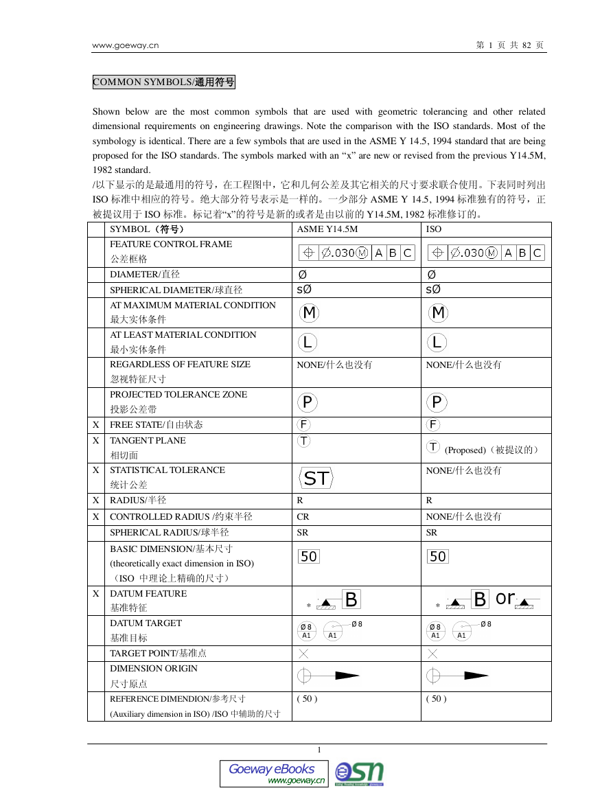
Shown below are the most common symbols that are used with geometric tolerancing and other related
dimensional requirements on engineering drawings. Note the comparison with the ISO standards. Most of the
symbology is identical. There are a few symbols that are used in the ASME Y 14.5, 1994 standard that are being
proposed for the ISO standards. The symbols marked with an “x” are new or revised from the previous Y14.5M,
1982 standard.
/
ISO ASME Y 14.5, 1994
ISO “x” Y14.5M, 1982
ASME Y14.5M
ISO
SYMBOL
FEATURE CONTROL FRAME
DIAMETER/
SPHERICAL DIAMETER/
AT MAXIMUM MATERIAL CONDITION
AT LEAST MATERIAL CONDITION
REGARDLESS OF FEATURE SIZE
PROJECTED TOLERANCE ZONE
NONE/
NONE/
X FREE STATE/
X TANGENT PLANE
X STATISTICAL TOLERANCE
X RADIUS/
X CONTROLLED RADIUS /
SPHERICAL RADIUS/
BASIC DIMENSION/
(theoretically exact dimension in ISO)
ISO
X DATUM FEATURE
DATUM TARGET
TARGET POINT/
DIMENSION ORIGIN
REFERENCE DIMENDION/
(Auxiliary dimension in ISO) /ISO
R
CR
SR
*
( 50 )
1
(Proposed)
NONE/
R
NONE/
SR
*
( 50 )
www.goeway.cnGoeway eBookswww.goeway.cn�
NUMBER OF PLACES /
COUNTERBORE/SPOTFACE
/
COUNTERSINK/
DEPTH/DEEP/
SQUARE/
ALL AROUND/
DIMENSION NOT TO SCALE
ARC LENGTH/
X BETWEEN/
SLOPE/
2 82
8x
8x
NONE
NONE
CONICAL TAPER/
ENVELOPE PRINCIPLE
NONE(implied)/
Note: * May be filled or not filled/*
RADIUS, CONTROLLED RADIUS/
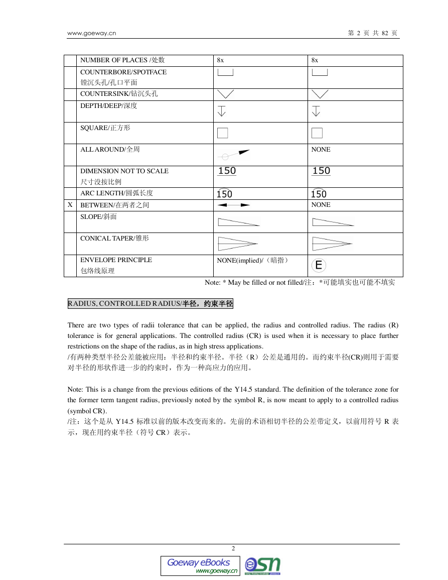
There are two types of radii tolerance that can be applied, the radius and controlled radius. The radius (R)
tolerance is for general applications. The controlled radius (CR) is used when it is necessary to place further
restrictions on the shape of the radius, as in high stress applications.
/R(CR)
Note: This is a change from the previous editions of the Y14.5 standard. The definition of the tolerance zone for
the former term tangent radius, previously noted by the symbol R, is now meant to apply to a controlled radius
(symbol CR).
/ Y14.5 R
CR
2
www.goeway.cnGoeway eBookswww.goeway.cn�
3 82
STATISTICAL TOLERANCING SYMBOL/
Often, tolerances are calculated on an arithmetic basis. Tolerances are assigned to individual features on a
component by dividing the total assembly tolerance by the number of components and assigning a portion of this
tolerance to each component. When tolerances are stacked up in this manner, the tolerance may become very
restrictive or tight.
/
Statistical tolerancing is the assignment of tolerances to related components of an assembly on the basis of sound
statistics. An example is: the assembly tolerance is equal to the square root of the sum of the squares of the
individual tolerances.
/
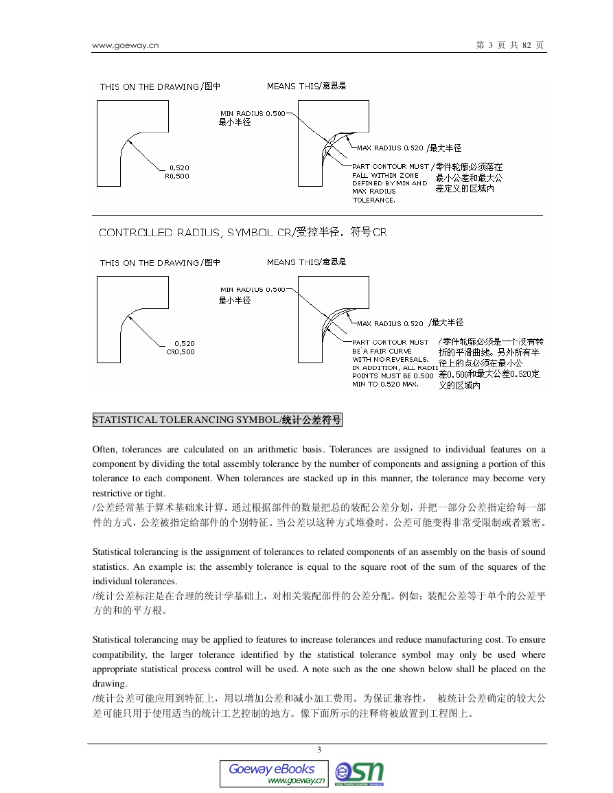
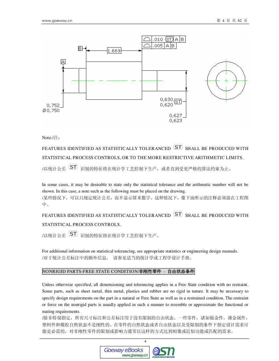
Statistical tolerancing may be applied to features to increase tolerances and reduce manufacturing cost. To ensure
compatibility, the larger tolerance identified by the statistical tolerance symbol may only be used where
appropriate statistical process control will be used. A note such as the one shown below shall be placed on the
drawing.
/
3
www.goeway.cnGoeway eBookswww.goeway.cn�
4 82
Note:/
FEATURES IDENTIFIED AS STATISTICALLY TOLERANCED
STATISTICAL PROCESS CONTROLS, OR TO THE MORE RESTRICTIVE ARITHMETIC LIMITS.
SHALL BE PRODUCED WITH
/
In some cases, it may be desirable to state only the statistical tolerance and the arithmetic number will not be
shown. In this case, a note such as the following must be placed on the drawing.
/
FEATURES IDENTIFIED AS STATISTICALLY TOLERANCED
STATISTICAL PROCESS CONTROLS.
/
SHALL BE PRODUCED WITH
For additional information on statistical tolerancing, see appropriate statistics or engineering design manuals.
/
NONRIGID PARTS-FREE STATE CONDITION/ -
Unless otherwise specified, all dimensioning and tolerancing applies in a Free State condition with no restraint.
Some parts, such as sheet metal, thin metal, plastics and rubber are no rigid in nature. It may be necessary to
specify design requirements on the part in a natural or Free State as well as in a restrained condition. The restraint
or force on the nonrigid parts is usually applied in such a manner to resemble or approximate the functional or
mating requirements.
/
4
www.goeway.cnGoeway eBookswww.goeway.cn�
5 82
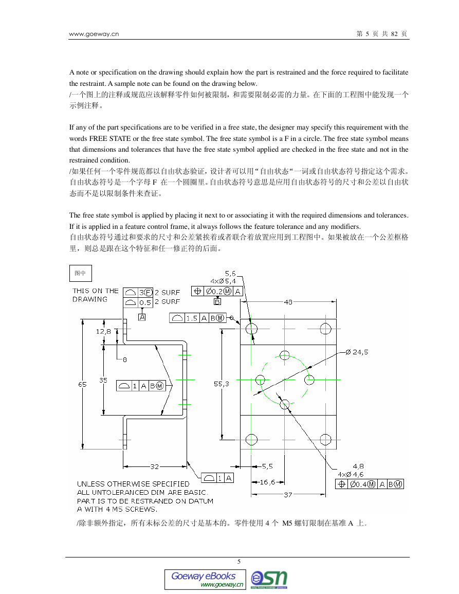
A note or specification on the drawing should explain how the part is restrained and the force required to facilitate
the restraint. A sample note can be found on the drawing below.
/
If any of the part specifications are to be verified in a free state, the designer may specify this requirement with the
words FREE STATE or the free state symbol. The free state symbol is a F in a circle. The free state symbol means
that dimensions and tolerances that have the free state symbol applied are checked in the free state and not in the
restrained condition.
/
F
The free state symbol is applied by placing it next to or associating it with the required dimensions and tolerances.
If it is applied in a feature control frame, it always follows the feature tolerance and any modifiers.
/ 4 M5 A
5
www.goeway.cnGoeway eBookswww.goeway.cn�
FEATURE CONTROL FRAME /
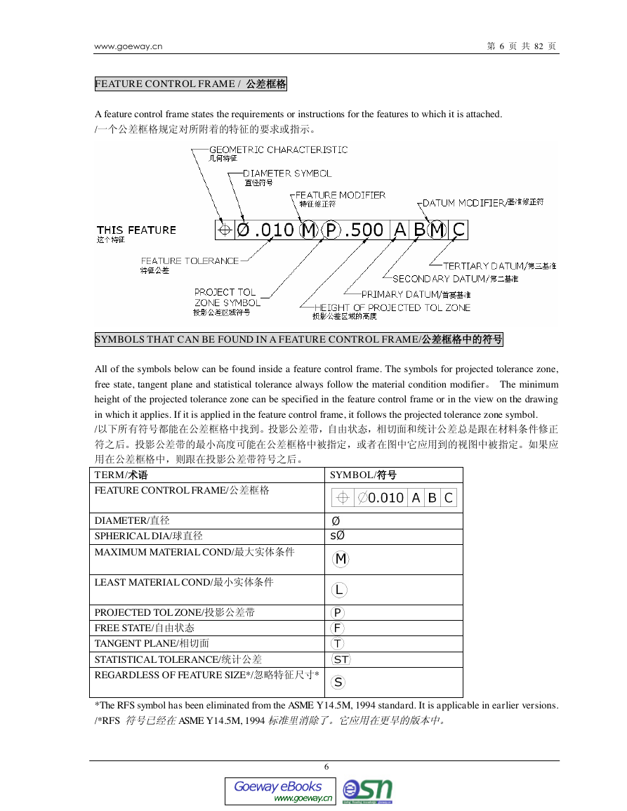
A feature control frame states the requirements or instructions for the features to which it is attached.
/
6 82
SYMBOLS THAT CAN BE FOUND IN A FEATURE CONTROL FRAME/
All of the symbols below can be found inside a feature control frame. The symbols for projected tolerance zone,
free state, tangent plane and statistical tolerance always follow the material condition modifier The minimum
height of the projected tolerance zone can be specified in the feature control frame or in the view on the drawing
in which it applies. If it is applied in the feature control frame, it follows the projected tolerance zone symbol.
/
TERM/
FEATURE CONTROL FRAME/
SYMBOL/
DIAMETER/
SPHERICAL DIA/
MAXIMUM MATERIAL COND/
LEAST MATERIAL COND/
PROJECTED TOL ZONE/
FREE STATE/
TANGENT PLANE/
STATISTICAL TOLERANCE/
REGARDLESS OF FEATURE SIZE*/*
*The RFS symbol has been eliminated from the ASME Y 14.5M, 1994 standard. It is applicable in earlier versions.
/*RFS ASME Y 14.5M, 1994
6
www.goeway.cnGoeway eBookswww.goeway.cn�
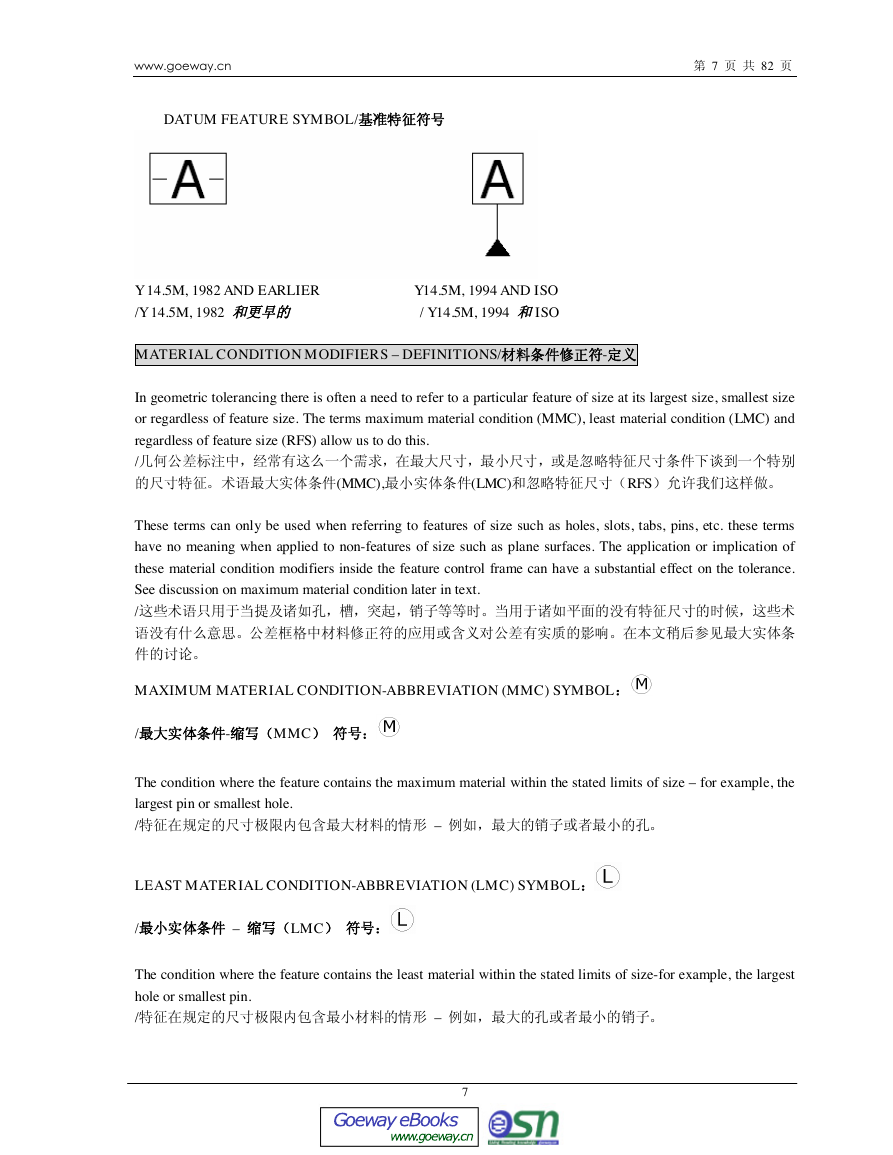
DATUM FEATURE SYMBOL/
7 82
Y 14.5M, 1982 AND EARLIER
/Y 14.5M, 1982
Y14.5M, 1994 AND ISO
/ Y14.5M, 1994 ISO
MATERIAL CONDITION MODIFIERS – DEFINITIONS/-
In geometric tolerancing there is often a need to refer to a particular feature of size at its largest size, smallest size
or regardless of feature size. The terms maximum material condition (MMC), least material condition (LMC) and
regardless of feature size (RFS) allow us to do this.
/
(MMC),(LMC)RFS
These terms can only be used when referring to features of size such as holes, slots, tabs, pins, etc. these terms
have no meaning when applied to non-features of size such as plane surfaces. The application or implication of
these material condition modifiers inside the feature control frame can have a substantial effect on the tolerance.
See discussion on maximum material condition later in text.
/
MAXIMUM MATERIAL CONDITION-ABBREVIATION (MMC) SYMBOL
/-MMC
The condition where the feature contains the maximum material within the stated limits of size – for example, the
largest pin or smallest hole.
/ –
LEAST MATERIAL CONDITION-ABBREVIATION (LMC) SYMBOL
/ – LMC
The condition where the feature contains the least material within the stated limits of size-for example, the largest
hole or smallest pin.
/ –
7
www.goeway.cnGoeway eBookswww.goeway.cn�
8 82
REGARDLESS OF FEATURE SIZE-ABBREVIATION (RFS)/ – RFS
The term used to indicate that a geometric tolerance applies at any increment of size of the feature within its size
limits. /
In the current ASME Y 14.5M, 1994 standard there is no symbol for RFS. (Unless otherwise specified all
geometric tolerances are implied RFS. See rule 2.) In previous editions of the Y14.5 standard the
was used for RFS.
/ ASME Y 14.5M, 1994 RFS RFS
symbol
2 Y14.5 RFS
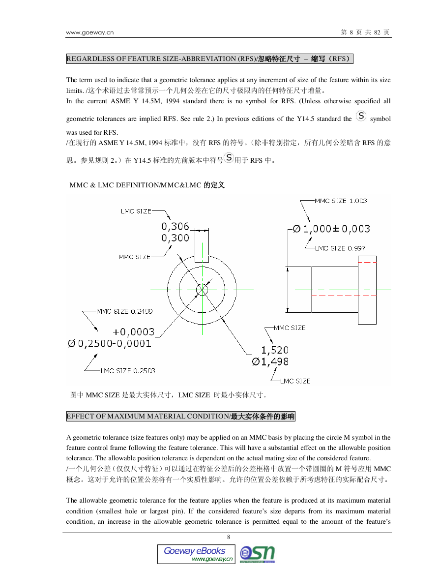
MMC & LMC DEFINITION/MMC&LMC
MMC SIZE LMC SIZE
EFFECT OF MAXIMUM MATERIAL CONDITION/
A geometric tolerance (size features only) may be applied on an MMC basis by placing the circle M symbol in the
feature control frame following the feature tolerance. This will have a substantial effect on the allowable position
tolerance. The allowable position tolerance is dependent on the actual mating size of the considered feature.
/ M MMC
The allowable geometric tolerance for the feature applies when the feature is produced at its maximum material
condition (smallest hole or largest pin). If the considered feature’s size departs from its maximum material
condition, an increase in the allowable geometric tolerance is permitted equal to the amount of the feature’s
8
www.goeway.cnGoeway eBookswww.goeway.cn�


 2023年江西萍乡中考道德与法治真题及答案.doc
 2012年重庆南川中考生物真题及答案.doc
 2013年江西师范大学地理学综合及文艺理论基础考研真题.doc
 2020年四川甘孜小升初语文真题及答案I卷.doc
 2020年注册岩土工程师专业基础考试真题及答案.doc
 2023-2024学年福建省厦门市九年级上学期数学月考试题及答案.doc
 2021-2022学年辽宁省沈阳市大东区九年级上学期语文期末试题及答案.doc
 2022-2023学年北京东城区初三第一学期物理期末试卷及答案.doc
 2018上半年江西教师资格初中地理学科知识与教学能力真题及答案.doc
 2012年河北国家公务员申论考试真题及答案-省级.doc
 2020-2021学年江苏省扬州市江都区邵樊片九年级上学期数学第一次质量检测试题及答案.doc
 2022下半年黑龙江教师资格证中学综合素质真题及答案.doc