OEM
SICLIMAT® SAPHIR
AC Controllers
for control, switching and monitoring functions
ACX36...
KNX + Modbus RTU
LON + Modbus RTU
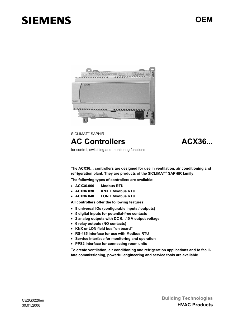
The ACX36… controllers are designed for use in ventilation, air conditioning and
refrigeration plant. They are products of the SICLIMAT® SAPHIR family.
The following types of controllers are available:
• ACX36.000 Modbus RTU
• ACX36.030
• ACX36.040
All controllers offer the following features:
• 8 universal IOs (configurable inputs / outputs)
• 5 digital inputs for potential-free contacts
• 2 analog outputs with DC 0…10 V output voltage
• 6 relay outputs (NO contacts)
• KNX or LON field bus "on board"
• RS-485 interface for use with Modbus RTU
• Service interface for monitoring and operation
• PPS2 interface for connecting room units
To create ventilation, air conditioning and refrigeration applications and to facili-
tate commissioning, powerful engineering and service tools are available.
CE2Q3226en
30.01.2006
Building Technologies
HVAC Products
�
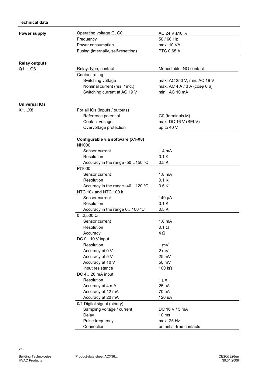
Technical data
Power supply
Relay outputs
Q1_...Q6_
Universal IOs
X1…X8
Operating voltage G, G0
Frequency
Power consumption
Fusing (internally, self-resetting)
AC 24 V ±10 %
50 / 60 Hz
max. 10 VA
PTC 0.65 A
Relay: type, contact
Contact rating
Switching voltage
Nominal current (res. / ind.)
Switching current at AC 19 V
Monostable, NO contact
max. AC 250 V, min. AC 19 V
max. AC 4 A / 3 A (cosφ 0.6)
min. AC 10 mA
For all IOs (inputs / outputs)
Reference potential
Contact voltage
Overvoltage protection
Configurable via software (X1-X8)
Ni1000
Sensor current
Resolution
Accuracy in the range -50…150 °C
Pt1000
Sensor current
Resolution
Accuracy in the range -40…120 °C
NTC 10k and NTC 100 k
Sensor current
Resolution
Accuracy in the range 0…100 °C
0...2,500 Ω
Sensor current
Resolution
Accuracy
DC 0...10 V input
Resolution
Accuracy at 0 V
Accuracy at 5 V
Accuracy at 10 V
Input resistance
DC 4…20 mA input
Resolution
Accuracy at 4 mA
Accuracy at 12 mA
Accuracy at 20 mA
0/1 Digital signal (binary)
Sampling voltage / current
Delay
Pulse frequency
Connection
G0 (terminals M)
max. DC 16 V (SELV)
up to 40 V
1.4 mA
0.1 K
0.5 K
1.8 mA
0.1 K
0.5 K
140 µA
0.1 K
0.5 K
1.8 mA
0.1 Ω
4 Ω
1 mV
2 mV
25 mV
50 mV
100 kΩ
1 µA
25 uA
70 uA
120 uA
DC 16 V / 5 mA
10 ms
max. 25 Hz
potential-free contacts
2/6
Building Technologies
HVAC Products
Product-data sheet ACX36…
CE2Q3226en
30.01.2006
�
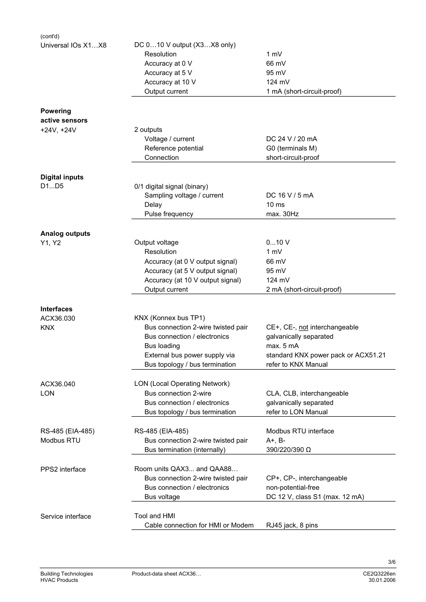
(cont'd)
Universal IOs X1…X8
Powering
active sensors
+24V, +24V
Digital inputs
D1...D5
Analog outputs
Y1, Y2
Interfaces
ACX36.030
KNX
ACX36.040
LON
RS-485 (EIA-485)
Modbus RTU
PPS2 interface
Service interface
DC 0…10 V output (X3…X8 only)
Resolution
Accuracy at 0 V
Accuracy at 5 V
Accuracy at 10 V
Output current
1 mV
66 mV
95 mV
124 mV
1 mA (short-circuit-proof)
2 outputs
Voltage / current
Reference potential
Connection
0/1 digital signal (binary)
Sampling voltage / current
Delay
Pulse frequency
DC 24 V / 20 mA
G0 (terminals M)
short-circuit-proof
DC 16 V / 5 mA
10 ms
max. 30Hz
Output voltage
Resolution
Accuracy (at 0 V output signal)
Accuracy (at 5 V output signal)
Accuracy (at 10 V output signal)
Output current
0...10 V
1 mV
66 mV
95 mV
124 mV
2 mA (short-circuit-proof)
KNX (Konnex bus TP1)
Bus connection 2-wire twisted pair
Bus connection / electronics
Bus loading
External bus power supply via
Bus topology / bus termination
CE+, CE-, not interchangeable
galvanically separated
max. 5 mA
standard KNX power pack or ACX51.21
refer to KNX Manual
LON (Local Operating Network)
Bus connection 2-wire
Bus connection / electronics
Bus topology / bus termination
CLA, CLB, interchangeable
galvanically separated
refer to LON Manual
RS-485 (EIA-485)
Bus connection 2-wire twisted pair
Bus termination (internally)
Modbus RTU interface
A+, B-
390/220/390 Ω
Room units QAX3... and QAA88…
Bus connection 2-wire twisted pair
Bus connection / electronics
Bus voltage
CP+, CP-, interchangeable
non-potential-free
DC 12 V, class S1 (max. 12 mA)
Tool and HMI
Cable connection for HMI or Modem
RJ45 jack, 8 pins
Building Technologies
HVAC Products
Product-data sheet ACX36…
3/6
CE2Q3226en
30.01.2006
�
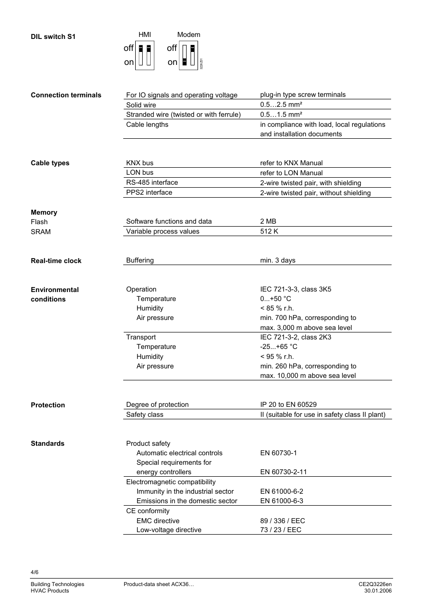
DIL switch S1
HMI
Modem
Connection terminals
off
on
1
0
Z
6
2
2
3
off
on
For IO signals and operating voltage
Solid wire
Stranded wire (twisted or with ferrule)
Cable lengths
KNX bus
LON bus
RS-485 interface
PPS2 interface
Cable types
Memory
Flash
SRAM
Real-time clock
Environmental
conditions
Protection
Standards
plug-in type screw terminals
0.5…2.5 mm²
0.5…1.5 mm²
in compliance with load, local regulations
and installation documents
refer to KNX Manual
refer to LON Manual
2-wire twisted pair, with shielding
2-wire twisted pair, without shielding
Software functions and data
Variable process values
2 MB
512 K
Buffering
min. 3 days
Operation
Temperature
Humidity
Air pressure
Transport
Temperature
Humidity
Air pressure
IEC 721-3-3, class 3K5
0...+50 °C
< 85 % r.h.
min. 700 hPa, corresponding to
max. 3,000 m above sea level
IEC 721-3-2, class 2K3
-25...+65 °C
< 95 % r.h.
min. 260 hPa, corresponding to
max. 10,000 m above sea level
Degree of protection
Safety class
IP 20 to EN 60529
II (suitable for use in safety class II plant)
Product safety
Automatic electrical controls
Special requirements for
energy controllers
Electromagnetic compatibility
Immunity in the industrial sector
Emissions in the domestic sector
CE conformity
EMC directive
Low-voltage directive
EN 60730-1
EN 60730-2-11
EN 61000-6-2
EN 61000-6-3
89 / 336 / EEC
73 / 23 / EEC
4/6
Building Technologies
HVAC Products
Product-data sheet ACX36…
CE2Q3226en
30.01.2006
�
General data
Printed circuit board
Dimensions of controller
Weight excl. packaging
Base
Housing
quadruple multilayer
178 x 132 x 57 mm
0.4 kg
plastic, light-grey RAL 7035
plastic, silver-grey RAL 7001
In order to protect against accidental contact with relay connections at voltages above
than 42 Veff, the device must be installed in an enclosure (preferably a control panel). It
must be impossible to open the enclosure without the aid of a key or tool.
AC 230 V cables must be double-insulated against safety extra low-voltage (SELV)
cables.
Engineering notes
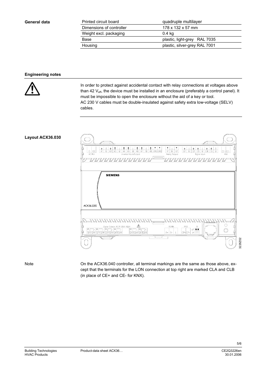
Layout ACX36.030
Note
On the ACX36.040 controller, all terminal markings are the same as those above, ex-
cept that the terminals for the LON connection at top right are marked CLA and CLB
(in place of CE+ and CE- for KNX).
2
0
Z
6
2
2
3
Building Technologies
HVAC Products
Product-data sheet ACX36…
5/6
CE2Q3226en
30.01.2006
�
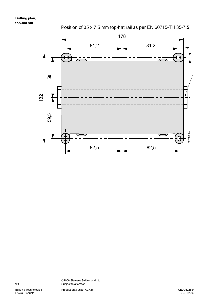
Drilling plan,
top-hat rail
Position of 35 x 7.5 mm top-hat rail as per EN 60715-TH 35-7.5
178
81,2
81,2
4
2
3
1
8
5
,
5
9
5
82,5
82,5
n
e
1
0
M
6
2
2
3
6/6
Building Technologies
HVAC Products
©2006 Siemens Switzerland Ltd
Subject to alteration
Product-data sheet ACX36…
CE2Q3226en
30.01.2006
�


 2023年江西萍乡中考道德与法治真题及答案.doc
 2012年重庆南川中考生物真题及答案.doc
 2013年江西师范大学地理学综合及文艺理论基础考研真题.doc
 2020年四川甘孜小升初语文真题及答案I卷.doc
 2020年注册岩土工程师专业基础考试真题及答案.doc
 2023-2024学年福建省厦门市九年级上学期数学月考试题及答案.doc
 2021-2022学年辽宁省沈阳市大东区九年级上学期语文期末试题及答案.doc
 2022-2023学年北京东城区初三第一学期物理期末试卷及答案.doc
 2018上半年江西教师资格初中地理学科知识与教学能力真题及答案.doc
 2012年河北国家公务员申论考试真题及答案-省级.doc
 2020-2021学年江苏省扬州市江都区邵樊片九年级上学期数学第一次质量检测试题及答案.doc
 2022下半年黑龙江教师资格证中学综合素质真题及答案.doc