User Manual
FINE™/Turbo v8 (including Euranus)
Flow Integrated Environment
- October 2007 -
N U M E R I C A L M E C H A N I C S A P P L I C A T I O N S
�
User Manual
FINE™/Turbo v8
Documentation v8a
NUMECA International
5, Avenue Franklin Roosevelt
1050 Brussels
Belgium
Tel: +32 2 647.83.11
Fax: +32 2 647.93.98
Web: http://www.numeca.com
N U M E R I C A L M E C H A N I C S A P P L I C A T I O N S
�
CHAPTER 1: Getting Started
1-1 Overview
1-2 Introduction
What is CFD?
Components
Multi-Tasking
Project Management
1-3 How To Use This Manual
Outline
Conventions
1-4 First Time Use
Basic Installation
Expert Graphics Options
1-5 How to start FINE™ Interface
1-6 Required Licenses
Standard FINE™ License
Additional Licenses
CHAPTER 2: Graphical User Interface
2-1 Overview
2-2 Project Selection
Create New Project
Open Existing Project
Grid Units & Project Configuration
2-3 Main Menu Bar
File Menu
Mesh Menu
Solver Menu
Modules Menu
2-4 Icon Bar
File Buttons
Grid Selection Bar
Solver Buttons
Module Buttons
User Mode
2-5 Computation Management
2-6 Graphical Area Management
Configuration Management
Parameters Management
View Area
Mesh Information
Parameters Area
Graphics Area
Viewing Buttons
2-7 Profile Management
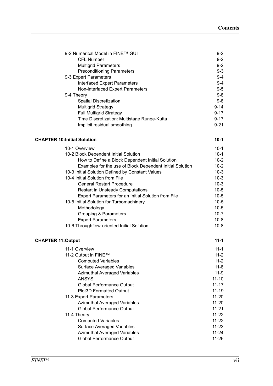
FINE™
Contents
1-1
1-1
1-1
1-1
1-3
1-3
1-3
1-5
1-5
1-5
1-6
1-6
1-6
1-7
1-8
1-8
1-8
2-1
2-1
2-2
2-2
2-4
2-4
2-5
2-5
2-9
2-10
2-11
2-12
2-12
2-12
2-13
2-13
2-14
2-14
2-15
2-15
2-15
2-16
2-17
2-18
2-18
2-18
2-21
iii
�
Contents
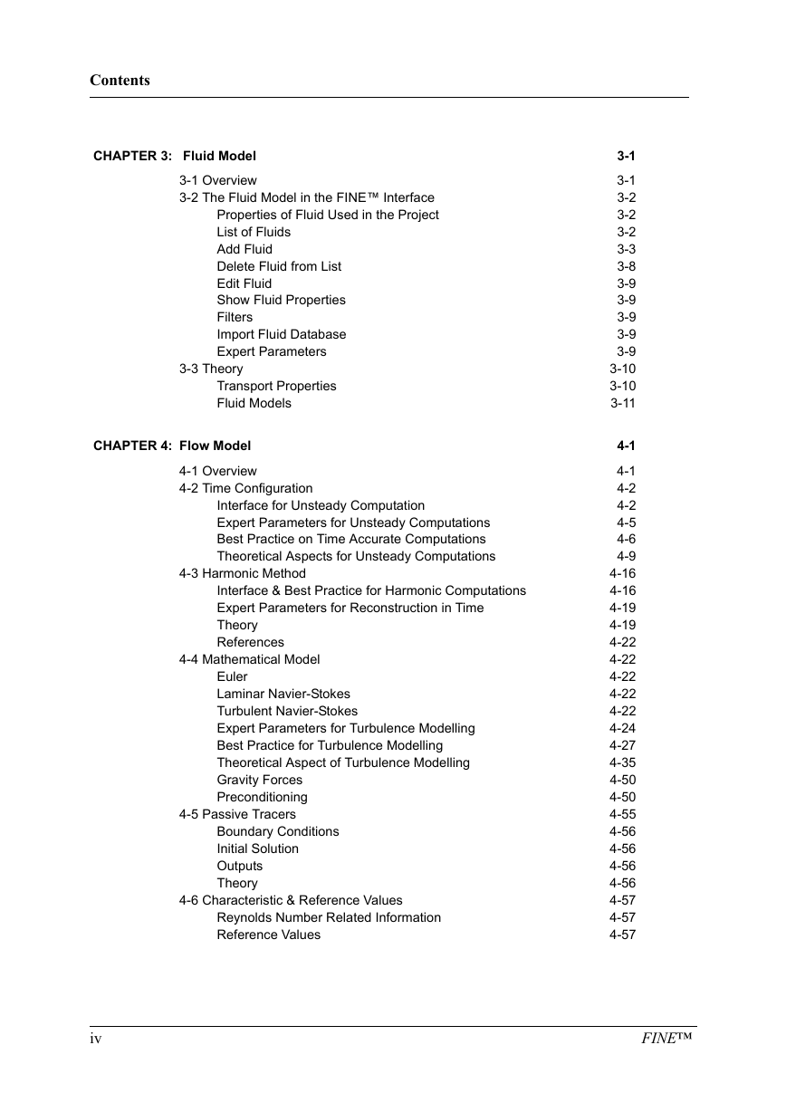
CHAPTER 3: Fluid Model
3-1 Overview
3-2 The Fluid Model in the FINE™ Interface
Properties of Fluid Used in the Project
List of Fluids
Add Fluid
Delete Fluid from List
Edit Fluid
Show Fluid Properties
Filters
Import Fluid Database
Expert Parameters
3-3 Theory
Transport Properties
Fluid Models
CHAPTER 4: Flow Model
4-1 Overview
4-2 Time Configuration
Interface for Unsteady Computation
Expert Parameters for Unsteady Computations
Best Practice on Time Accurate Computations
Theoretical Aspects for Unsteady Computations
4-3 Harmonic Method
Interface & Best Practice for Harmonic Computations
Expert Parameters for Reconstruction in Time
Theory
References
4-4 Mathematical Model
Euler
Laminar Navier-Stokes
Turbulent Navier-Stokes
Expert Parameters for Turbulence Modelling
Best Practice for Turbulence Modelling
Theoretical Aspect of Turbulence Modelling
Gravity Forces
Preconditioning
4-5 Passive Tracers
Boundary Conditions
Initial Solution
Outputs
Theory
4-6 Characteristic & Reference Values
Reynolds Number Related Information
Reference Values
3-1
3-1
3-2
3-2
3-2
3-3
3-8
3-9
3-9
3-9
3-9
3-9
3-10
3-10
3-11
4-1
4-1
4-2
4-2
4-5
4-6
4-9
4-16
4-16
4-19
4-19
4-22
4-22
4-22
4-22
4-22
4-24
4-27
4-35
4-50
4-50
4-55
4-56
4-56
4-56
4-56
4-57
4-57
4-57
iv
FINE™
�
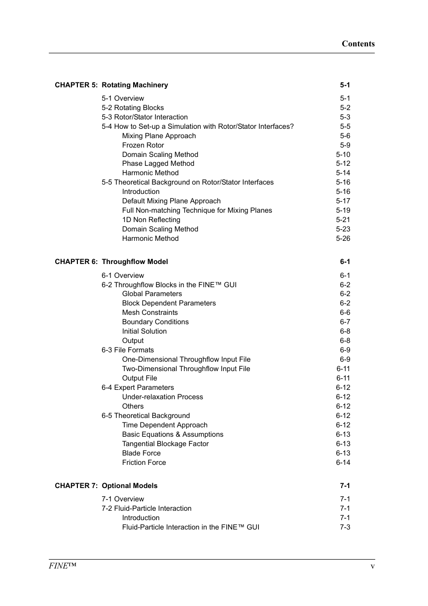
CHAPTER 5: Rotating Machinery
5-1 Overview
5-2 Rotating Blocks
5-3 Rotor/Stator Interaction
5-4 How to Set-up a Simulation with Rotor/Stator Interfaces?
Mixing Plane Approach
Frozen Rotor
Domain Scaling Method
Phase Lagged Method
Harmonic Method
5-5 Theoretical Background on Rotor/Stator Interfaces
Introduction
Default Mixing Plane Approach
Full Non-matching Technique for Mixing Planes
1D Non Reflecting
Domain Scaling Method
Harmonic Method
CHAPTER 6: Throughflow Model
6-1 Overview
6-2 Throughflow Blocks in the FINE™ GUI
Global Parameters
Block Dependent Parameters
Mesh Constraints
Boundary Conditions
Initial Solution
Output
6-3 File Formats
One-Dimensional Throughflow Input File
Two-Dimensional Throughflow Input File
Output File
6-4 Expert Parameters
Under-relaxation Process
Others
6-5 Theoretical Background
Time Dependent Approach
Basic Equations & Assumptions
Tangential Blockage Factor
Blade Force
Friction Force
CHAPTER 7: Optional Models
7-1 Overview
7-2 Fluid-Particle Interaction
Introduction
Fluid-Particle Interaction in the FINE™ GUI
FINE™
Contents
5-1
5-1
5-2
5-3
5-5
5-6
5-9
5-10
5-12
5-14
5-16
5-16
5-17
5-19
5-21
5-23
5-26
6-1
6-1
6-2
6-2
6-2
6-6
6-7
6-8
6-8
6-9
6-9
6-11
6-11
6-12
6-12
6-12
6-12
6-12
6-13
6-13
6-13
6-14
7-1
7-1
7-1
7-1
7-3
v
�
Contents
Specific Output
Expert Parameters
Theory
References
7-3 Conjugate Heat Transfer
Introduction
Conjugate Heat Transfer in the FINE™ GUI
Theory
7-4 Cooling/Bleed
Introduction
Cooling/Bleed Model in the FINE™ GUI
Expert Parameters
Theory
Cooling/Bleed Data File: ’.cooling-holes’
7-5 Transition Model
Introduction
Transition Model in the FINE™ GUI
Expert Parameters
Theory
CHAPTER 8: Boundary Conditions
8-1 Overview
8-2 Boundary Conditions in the FINE™ GUI
Inlet Condition
Outlet Condition
Periodic Condition
Solid Wall Boundary Condition
External Condition (Far-field)
8-3 Expert Parameters
Imposing Velocity Angles of Relative Flow
Extrapolation of Mass Flow at Inlet
Outlet Mass Flow Boundary Condition
Torque and Force Calculation
Euler or Navier-Stokes Wall for Viscous Flow
Pressure Condition at Solid Wall
8-4 Best Practice for Imposing Boundary Conditions
Compressible Flows
Incompressible or Low Speed Flow
Special Parameters (for Turbomachinery)
8-5 Theory
Inlet Boundary Conditions
Outlet Boundary Conditions
Solid Wall Boundary Conditions
Far-field Boundary Condition
CHAPTER 9: Numerical Model
9-1 Overview
7-7
7-8
7-8
7-11
7-11
7-11
7-11
7-13
7-15
7-15
7-16
7-32
7-32
7-33
7-38
7-38
7-39
7-40
7-41
8-1
8-1
8-1
8-3
8-6
8-9
8-10
8-13
8-14
8-14
8-14
8-14
8-14
8-15
8-15
8-15
8-15
8-16
8-16
8-17
8-17
8-24
8-27
8-30
9-1
9-1
vi
FINE™
�
9-2 Numerical Model in FINE™ GUI
CFL Number
Multigrid Parameters
Preconditioning Parameters
9-3 Expert Parameters
Interfaced Expert Parameters
Non-interfaced Expert Parameters
9-4 Theory
Spatial Discretization
Multigrid Strategy
Full Multigrid Strategy
Time Discretization: Multistage Runge-Kutta
Implicit residual smoothing
CHAPTER 10:Initial Solution
10-1 Overview
10-2 Block Dependent Initial Solution
How to Define a Block Dependent Initial Solution
Examples for the use of Block Dependent Initial Solution
10-3 Initial Solution Defined by Constant Values
10-4 Initial Solution from File
General Restart Procedure
Restart in Unsteady Computations
Expert Parameters for an Initial Solution from File
10-5 Initial Solution for Turbomachinery
Methodology
Grouping & Parameters
Expert Parameters
10-6 Throughflow-oriented Initial Solution
CHAPTER 11:Output
11-1 Overview
11-2 Output in FINE™
Computed Variables
Surface Averaged Variables
Azimuthal Averaged Variables
ANSYS
Global Performance Output
Plot3D Formatted Output
11-3 Expert Parameters
Azimuthal Averaged Variables
Global Performance Output
11-4 Theory
Computed Variables
Surface Averaged Variables
Azimuthal Averaged Variables
Global Performance Output
FINE™
Contents
9-2
9-2
9-2
9-3
9-4
9-4
9-5
9-8
9-8
9-14
9-17
9-17
9-21
10-1
10-1
10-1
10-2
10-2
10-3
10-3
10-3
10-5
10-5
10-5
10-5
10-7
10-8
10-8
11-1
11-1
11-2
11-2
11-8
11-9
11-10
11-17
11-19
11-20
11-20
11-21
11-22
11-22
11-23
11-24
11-26
vii
�
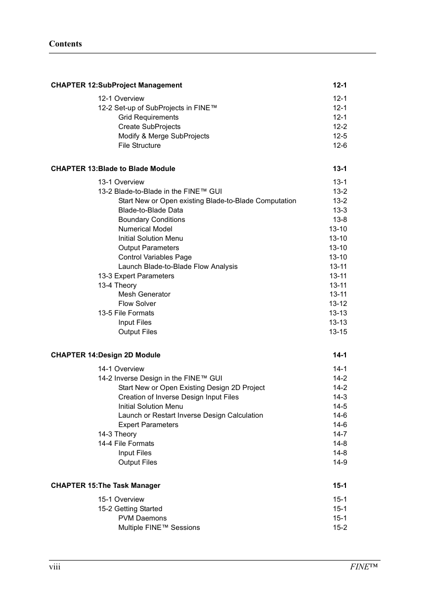
Contents
CHAPTER 12:SubProject Management
12-1 Overview
12-2 Set-up of SubProjects in FINE™
Grid Requirements
Create SubProjects
Modify & Merge SubProjects
File Structure
CHAPTER 13:Blade to Blade Module
13-1 Overview
13-2 Blade-to-Blade in the FINE™ GUI
Start New or Open existing Blade-to-Blade Computation
Blade-to-Blade Data
Boundary Conditions
Numerical Model
Initial Solution Menu
Output Parameters
Control Variables Page
Launch Blade-to-Blade Flow Analysis
13-3 Expert Parameters
13-4 Theory
Mesh Generator
Flow Solver
13-5 File Formats
Input Files
Output Files
CHAPTER 14:Design 2D Module
14-1 Overview
14-2 Inverse Design in the FINE™ GUI
Start New or Open Existing Design 2D Project
Creation of Inverse Design Input Files
Initial Solution Menu
Launch or Restart Inverse Design Calculation
Expert Parameters
14-3 Theory
14-4 File Formats
Input Files
Output Files
CHAPTER 15:The Task Manager
15-1 Overview
15-2 Getting Started
PVM Daemons
Multiple FINE™ Sessions
12-1
12-1
12-1
12-1
12-2
12-5
12-6
13-1
13-1
13-2
13-2
13-3
13-8
13-10
13-10
13-10
13-10
13-11
13-11
13-11
13-11
13-12
13-13
13-13
13-15
14-1
14-1
14-2
14-2
14-3
14-5
14-6
14-6
14-7
14-8
14-8
14-9
15-1
15-1
15-1
15-1
15-2
viii
FINE™
�




 2023年江西萍乡中考道德与法治真题及答案.doc
 2012年重庆南川中考生物真题及答案.doc
 2013年江西师范大学地理学综合及文艺理论基础考研真题.doc
 2020年四川甘孜小升初语文真题及答案I卷.doc
 2020年注册岩土工程师专业基础考试真题及答案.doc
 2023-2024学年福建省厦门市九年级上学期数学月考试题及答案.doc
 2021-2022学年辽宁省沈阳市大东区九年级上学期语文期末试题及答案.doc
 2022-2023学年北京东城区初三第一学期物理期末试卷及答案.doc
 2018上半年江西教师资格初中地理学科知识与教学能力真题及答案.doc
 2012年河北国家公务员申论考试真题及答案-省级.doc
 2020-2021学年江苏省扬州市江都区邵樊片九年级上学期数学第一次质量检测试题及答案.doc
 2022下半年黑龙江教师资格证中学综合素质真题及答案.doc