PCI Express™
Mini Card Electromechanical
Specification
Revision 1.1
March 28, 2005
�
PCI EXPRESS MINI CARD ELECTROMECHANICAL SPECIFICATION, REV 1.1
Revision
1.0
1.1
Revision History
Initial release.
Incorporated approved Errata and ECNs.
Date
6/02/03
3/28/05
PCI-SIG disclaims all warranties and liability for the use of this document and the information
contained herein and assumes no responsibility for any errors that may appear in this document, nor
does the PCI-SIG make a commitment to update the information contained herein.
Contact the PCI-SIG office to obtain the latest revision of the specification.
Questions regarding this specification or membership in PCI-SIG may be forwarded to:
Membership Services
www.pcisig.com
E-mail:
Phone:
Fax:
Technical Support
techsupp@pcisig.com
administration@pcisig.com
503-291-2569
503-297-1090
DISCLAIMER
This PCI Express Mini Card Electromechanical Specification is provided "as is" with no
warranties whatsoever, including any warranty of merchantability, noninfringement,
fitness for any particular purpose, or any warranty otherwise arising out of any proposal,
specification, or sample. PCI-SIG disclaims all liability for infringement of proprietary
rights, relating to use of information in this specification. No license, express or implied,
by estoppel or otherwise, to any intellectual property rights is granted herein.
PCI Express is a trademark of PCI-SIG.
All other product names are trademarks, registered trademarks, or service marks of their respective
owners.
2
Copyright © 2003-05 PCI-SIG
�
PCI EXPRESS MINI CARD ELECTROMECHANICAL SPECIFICATION, REV 1.1
Contents
1.
2.3.
2.4.
2.3.1.
2.3.2.
2.3.3.
INTRODUCTION ...................................................................................................................7
1.1. OVERVIEW ....................................................................................................................... 7
SPECIFICATION REFERENCES ........................................................................................... 9
1.2.
TARGETED APPLICATIONS ............................................................................................... 9
1.3.
FEATURES AND BENEFITS .............................................................................................. 10
1.4.
2. MECHANICAL SPECIFICATION ......................................................................................11
2.1. OVERVIEW ..................................................................................................................... 11
2.2. CARD SPECIFICATIONS................................................................................................... 11
2.2.1. Card Form Factor................................................................................................... 12
2.2.2. Card PCB Details ................................................................................................... 13
SYSTEM CONNECTOR SPECIFICATIONS .......................................................................... 17
System Connector.................................................................................................... 17
System Connector Parametric Specifications......................................................... 21
I/O Connector Area................................................................................................. 22
THERMAL GUIDELINES .................................................................................................. 23
3. ELECTRICAL SPECIFICATIONS ......................................................................................25
3.1. OVERVIEW ..................................................................................................................... 25
SYSTEM INTERFACE SIGNALS ........................................................................................ 25
3.2.
3.2.1. Power Sources and Grounds .................................................................................. 27
3.2.2. PCI Express Interface............................................................................................. 27
3.2.3. USB Interface.......................................................................................................... 28
3.2.4. Auxiliary Signals..................................................................................................... 28
3.2.4.1. Reference Clock................................................................................................ 28
3.2.4.2. CLKREQ# Signal ............................................................................................. 28
3.2.4.3. PERST# Signal ................................................................................................. 31
3.2.4.4. WAKE# Signal ................................................................................................. 32
3.2.4.5. SMBus............................................................................................................... 32
3.2.5. Communications Specific Signals........................................................................... 32
3.2.5.1. Status Indicators................................................................................................ 32
3.2.5.2. W_DISABLE# Signal....................................................................................... 33
3.2.6. User Identity Module (UIM) Interface.................................................................... 34
3.2.6.1. UIM_PWR ........................................................................................................ 34
3.2.6.2. UIM_RESET..................................................................................................... 34
3.2.6.3. UIM_CLK......................................................................................................... 35
3.2.6.4. UIM_VPP ......................................................................................................... 35
3.2.6.5. UIM_DATA...................................................................................................... 35
3.3. CONNECTOR PIN-OUT DEFINITIONS ............................................................................... 36
3.3.1. Grounds................................................................................................................... 37
3.3.2. Reserved Pins.......................................................................................................... 37
ELECTRICAL REQUIREMENTS......................................................................................... 37
3.4.1. Digital Interfaces .................................................................................................... 37
3.4.
3
�
PCI EXPRESS MINI CARD ELECTROMECHANICAL SPECIFICATION, REVISION 1.1
3.4.2. Power ...................................................................................................................... 40
A. SUPPLEMENTAL GUIDELINES FOR PCI EXPRESS MINI CARD CONNECTOR
TESTING.......................................................................................................................................41
A.1. TEST BOARDS ASSEMBLY.............................................................................................. 41
A.1.1. Base Board Assembly.............................................................................................. 42
A.1.2. Plug-in Cards Assembly.......................................................................................... 43
INSERTION LOSS MEASUREMENT................................................................................... 44
A.2.
A.3. RETURN LOSS MEASUREMENT....................................................................................... 44
A.4. NEAR END CROSSTALK MEASUREMENT ........................................................................ 44
I/O CONNECTOR GUIDELINES........................................................................................47
B.1. WIRE-LINE MODEMS...................................................................................................... 47
IEEE 802.3 WIRED ETHERNET ...................................................................................... 47
B.2.
B.3.
IEEE 802.11 WIRELESS ETHERNET............................................................................... 47
B.
4
�
PCI EXPRESS MINI CARD ELECTROMECHANICAL SPECIFICATION, REVISION 1.1
Figures
FIGURE 1-1: PCI EXPRESS MINI CARD ADD-IN CARD INSTALLED IN A MOBILE PLATFORM........... 8
FIGURE 1-2: LOGICAL REPRESENTATION OF THE PCI EXPRESS MINI CARD SPECIFICATION........... 8
FIGURE 2-1: CARD FORM FACTOR (MODEM EXAMPLE APPLICATION SHOWN) ............................ 12
FIGURE 2-2: CARD TOP AND BOTTOM .......................................................................................... 13
FIGURE 2-3: CARD TOP AND BOTTOM DETAILS A AND B............................................................. 14
FIGURE 2-4: CARD EDGE .............................................................................................................. 15
FIGURE 2-5: CARD COMPONENT KEEP OUT AREAS...................................................................... 16
FIGURE 2-6: PCI EXPRESS MINI CARD SYSTEM CONNECTOR....................................................... 17
FIGURE 2-7: RECOMMENDED SYSTEM BOARD LAYOUT (SINGLE SOCKET)................................... 18
FIGURE 2-8: RECOMMENDED SYSTEM BOARD LAYOUT (DETAIL D) ............................................ 19
FIGURE 2-9: RECOMMENDED SYSTEM BOARD LAYOUT (DUAL SOCKET) ..................................... 20
FIGURE 2-10: I/O CONNECTOR LOCATION AREAS........................................................................ 23
FIGURE 2-11: POWER DENSITY UNIFORM LOADING AT 80 PERCENT COVERAGE ......................... 24
FIGURE 3-1: POWER-UP CLKREQ# TIMING ................................................................................ 30
FIGURE 3-2: CLKREQ# CLOCK CONTROL TIMINGS .................................................................... 31
Tables
TABLE 2-1: SYSTEM CONNECTOR PHYSICAL REQUIREMENTS ...................................................... 21
TABLE 2-2: SYSTEM CONNECTOR MECHANICAL PERFORMANCE REQUIREMENTS........................ 21
TABLE 2-3: SYSTEM CONNECTOR ELECTRICAL PERFORMANCE REQUIREMENTS.......................... 22
TABLE 2-4: SYSTEM CONNECTOR ENVIRONMENTAL PERFORMANCE REQUIREMENTS.................. 22
TABLE 3-1: PCI EXPRESS MINI CARD SYSTEM INTERFACE SIGNALS............................................ 25
TABLE 3-2: POWER-UP CLKREQ# TIMINGS................................................................................ 30
TABLE 3-3: CLKREQ# CLOCK CONTROL TIMINGS ..................................................................... 31
TABLE 3-4: DEFINED LED STATES............................................................................................... 33
TABLE 3-5: RECOMMENDED USE FOR LED INDICATORS BY WIRELESS CLASSES......................... 33
TABLE 3-6: SYSTEM CONNECTOR PIN-OUT................................................................................... 36
TABLE 3-7: SIGNAL INTEGRITY REQUIREMENTS AND TEST PROCEDURES .................................... 38
TABLE 3-8: POWER RATINGS........................................................................................................ 40
5
�
PCI EXPRESS MINI CARD ELECTROMECHANICAL SPECIFICATION, REVISION 1.1
6
�
PCI EXPRESS MINI CARD ELECTROMECHANICAL SPECIFICATION, REVISION 1.1
1
1.
Introduction
1.1. Overview
This specification defines an implementation for small form factor PCI Express cards. The
specification uses a qualified sub-set of the same signal protocol, electrical definitions, and
configuration definitions as the PCI Express Base Specification, Revision 1.0a. Where this specification
does not explicitly define PCI Express characteristics, the PCI Express Base Specification governs.
The primary differences between a PCI Express add-in card (as defined by the PCI Express Card
Electromechanical Specification) and a PCI Express Mini Card add-in card is a unique card form factor
optimized for mobile computing platforms and a card-system interconnection optimized for
communication applications. Specifically, PCI Express Mini Card add-in cards are smaller and have
smaller connectors than standard PCI Express add-in cards.
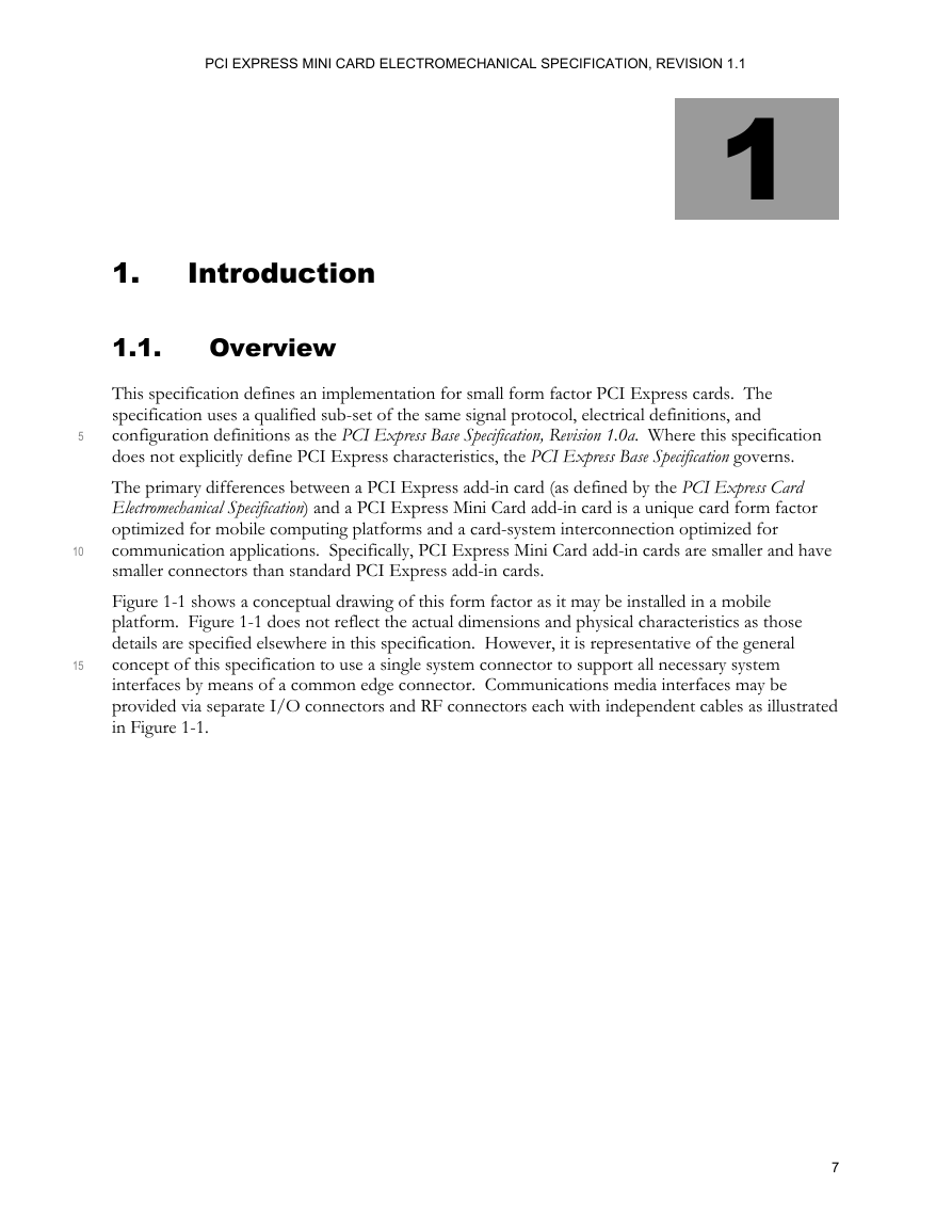
Figure 1-1 shows a conceptual drawing of this form factor as it may be installed in a mobile
platform. Figure 1-1 does not reflect the actual dimensions and physical characteristics as those
details are specified elsewhere in this specification. However, it is representative of the general
concept of this specification to use a single system connector to support all necessary system
interfaces by means of a common edge connector. Communications media interfaces may be
provided via separate I/O connectors and RF connectors each with independent cables as illustrated
in Figure 1-1.
5
10
15
7
�
PCI EXPRESS MINI CARD ELECTROMECHANICAL SPECIFICATION, REVISION 1.1
Figure 1-1: PCI Express Mini Card Add-in Card Installed in a Mobile Platform
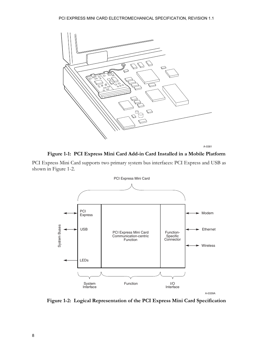
PCI Express Mini Card supports two primary system bus interfaces: PCI Express and USB as
shown in Figure 1-2.
A-0381
PCI Express Mini Card
s
e
s
u
B
m
e
t
s
y
S
PCI
Express
USB
LEDs
PCI Express Mini Card
Communication-centric
Function
Function-
Specific
Connector
System
Interface
Function
I/O
Interface
Modem
Ethernet
Wireless
A-0339A
Figure 1-2: Logical Representation of the PCI Express Mini Card Specification
8
�



 2023年江西萍乡中考道德与法治真题及答案.doc
 2012年重庆南川中考生物真题及答案.doc
 2013年江西师范大学地理学综合及文艺理论基础考研真题.doc
 2020年四川甘孜小升初语文真题及答案I卷.doc
 2020年注册岩土工程师专业基础考试真题及答案.doc
 2023-2024学年福建省厦门市九年级上学期数学月考试题及答案.doc
 2021-2022学年辽宁省沈阳市大东区九年级上学期语文期末试题及答案.doc
 2022-2023学年北京东城区初三第一学期物理期末试卷及答案.doc
 2018上半年江西教师资格初中地理学科知识与教学能力真题及答案.doc
 2012年河北国家公务员申论考试真题及答案-省级.doc
 2020-2021学年江苏省扬州市江都区邵樊片九年级上学期数学第一次质量检测试题及答案.doc
 2022下半年黑龙江教师资格证中学综合素质真题及答案.doc