LR9552
GPS Module
i
�
1.
INTRODUCTION..................................................................................................................1
1.1.
FEATURES.......................................................................................................... 1
HARDWARE AND SOFTWARE ........................................................................................... 1
PERFORMANCE .............................................................................................................. 1
INTERFACE .................................................................................................................... 1
2. MODULE ARCHITECTURE ..............................................................................................2
2.1. DIMENSIONS ....................................................................................................... 3
2.2. SOFTWARE FEATURES ........................................................................................ 3
2.3. ENVIRONMENTAL SPECIFICATION ......................................................................... 4
2.4. REFERENCE DESIGN............................................................................................ 4
2.5. REGULATIONS COMPLIANCE................................................................................. 5
3. PERFORMANCE CHARACTERISTICS...........................................................................7
3.1. POSITION AND VELOCITY ACCURACY..................................................................... 7
3.2. DYNAMIC CONSTRAINS ........................................................................................ 7
3.3. ACQUISITION TIME 1............................................................................................. 7
3.4.
TIMING 1PPS OUTPUT......................................................................................... 8
3.5. SENSITIVITY........................................................................................................ 8
4. HARDWARE INTERFACE POWER SUPPLY.................................................................9
SPECIFICATIONS.................................................................................................. 9
I. Pin Positions ....................................................................................................................9
II. Pin Assignment...............................................................................................................10
5. SOFTWARE INTERFACE.................................................................................................11
4.1.
6. MECHANICAL DRAWING AND FOOTPRINT ............................................................12
6.1. OUTLINE DRAWING ........................................................................................... 12
7. PACKAGE............................................................................................................................13
7.1. PACKAGE SPECIFICATIONS ................................................................................ 13
8. ROHS COMPLIANT INFORMATION............................................................................14
8.1. ROHS SOLDERING PROFILE ............................................................................... 14
Reflow Profile.........................................................................................................................14
GLOSSARY..................................................................................................................................15
ii
�
1. Introduction
LR9552 Manual V04
The Leadtek GPS 9952 module (LR9552) is a high sensitivity and very compact smart antenna module,
with built in GPS receiver circuit. This 20-channel global positioning system (GPS) receiver is
designed for a wide range of OEM applications and is based on the fast and deep GPS signal search
capabilities of SiRFStarIII™ architecture. Leadtek GPS 9552 is designed to allow quick and easy
integration into GPS-related applications such as:
λ
λ Car and Marine Navigation
λ
Fleet Management /Asset Tracking
λ AVL and Location-Based Services
λ Hand-Held Device for Personal Positioning and Navigation
PDA, Pocket PC, and other computing devices
1.1. Features
Hardware and Software
λ Based on the high performance features of the SiRF GSC3f/LP single chip
λ Compact module size for easy integration: 25 x 25 x 8.9 mm (with 4 mm patch antenna)
25 x 25 x 6.9 mm (with 2 mm patch antenna) [option]
λ
Fully automatic assembly: reflow solder assembly ready
λ Hardware compatible with SiRF GSW3.2 serial software
Performance
λ Cold/Warm/Hot Start Time: 42/38/1 sec.
λ Reacquisition Time: 0.1 second.
λ RF Metal Shield for best performance in noisy environments.
Interface
λ RS232 or TTL (option) level serial port for GPS communications interface
λ
λ Baud Rate: 4800 ~ 57600 baud (default 4800).
Protocol: NMEA-0183/SiRF Binary (default NMEA).
© 2006 Leadtek Research Inc. All rights reserved.
Preliminary Confidential - Information is subject to change without prior notice.
Page 1/18
�
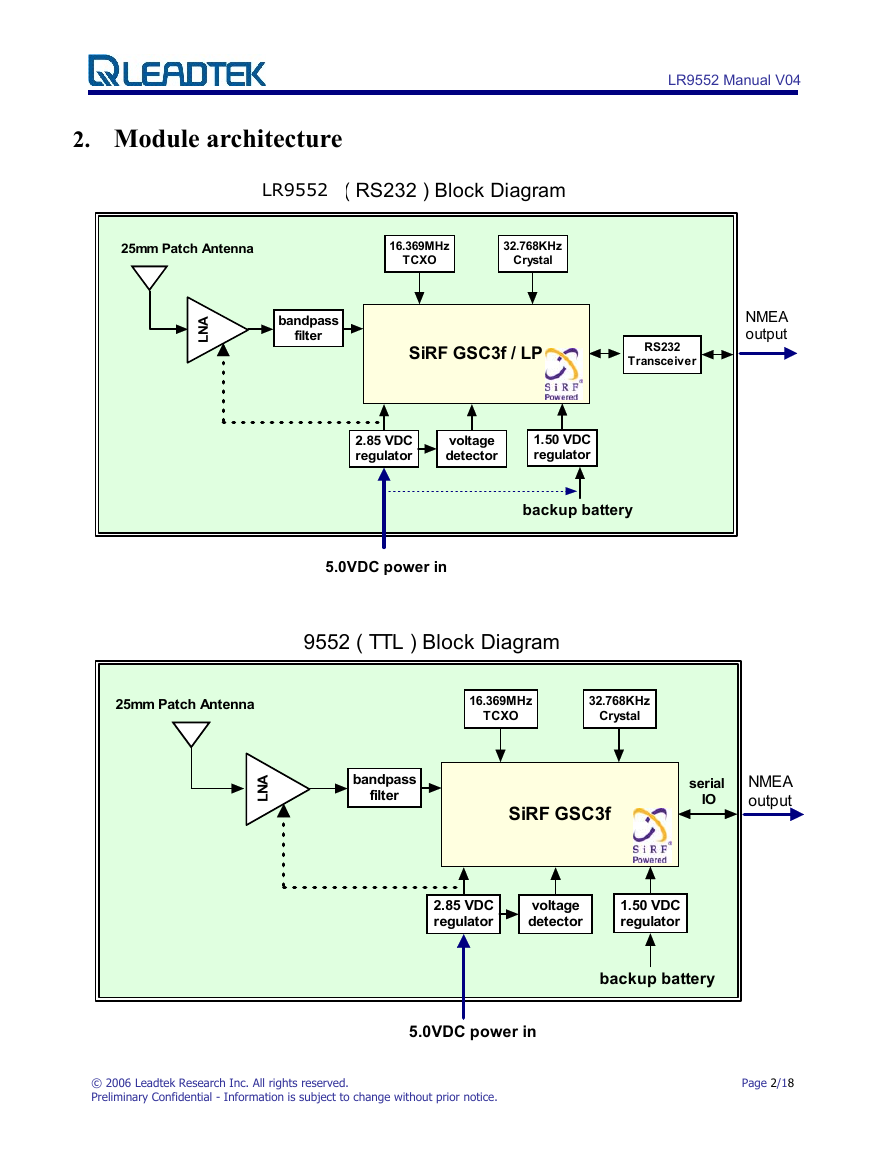
2. Module architecture
9552LP ( RS232 ) Block Diagram
LR9552
25mm Patch Antenna
16.369MHz
TCXO
32.768KHz
Crystal
LR9552 Manual V04
A
N
L
bandpass
filter
SiRF GSC3f / LP
RS232
Transceiver
NMEA
output
2.85 VDC
regulator
voltage
detector
1.50 VDC
regulator
backup battery
5.0VDC power in
9552 ( TTL ) Block Diagram
25mm Patch Antenna
16.369MHz
TCXO
32.768KHz
Crystal
A
N
L
bandpass
filter
SiRF GSC3f
serial
IO
NMEA
output
2.85 VDC
regulator
voltage
detector
1.50 VDC
regulator
backup battery
© 2006 Leadtek Research Inc. All rights reserved.
Preliminary Confidential - Information is subject to change without prior notice.
5.0VDC power in
Page 2/18
�
2.1. Dimensions
LR9552 Manual V04
The Physical dimensions of the Leadtek 9552 GPS Module are as follow:
Items
Length
Width
Description
25.0 ± 0.3 mm
25.0 ± 0.3 mm
8.90 ± 0.3 mm
6.90 ± 0.3 mm
13.0g (w/ 4mm patch antenna)
8.0g (w/ 2mm patch antenna)
Height
Weight
2.2. Software Features
The Leadtek 9552 module includes GSW3.2., high sensitivity software solution. For
SiRFStarIII/LP receivers, the default configuration is as follows:
Item
Core of firmware
Baud rate
Code type
Datum
Protocol message
Output frequency
3.2
Description
SiRF GSW
4800, 9600, 19200, 38400 or 57600 bps (default 4800)
NMEA-0183 ASCII
WGS-84
GGA(1sec),
1 Hz
GSA(5sec), GSV(5sec), RMC(1sec),VTG(1sec)
© 2006 Leadtek Research Inc. All rights reserved.
Preliminary Confidential - Information is subject to change without prior notice.
Page 3/18
�
2.3.
Environmental Specification
LR9552 Manual V04
Item
Operating temperature rang (note)
Storage temperature range
Humidity
Altitude
Velocity
Jerk
Acceleration
Description
-30 deg. C to +60 deg. C
-30 deg. C to +65 deg. C
up to 95% non-condensing or a wet
bulb temperature of +35 deg. C
18,000 meters (60,000 feet) max.
515 meters/second (1000 knots) max.
20 meters/second3, max.
4g, max.
Note: The module can be operated between -30℃~+85℃, but higher temperature may cause internal Li
backup battery deterioration that will influence the performance of GPS hot start.
2.4. Reference design
The user can use a PMOS to control 9552 power on or off as below:
VCC 5.0 VDC
To 9552LP pin7 VCC_5V
IRLML6402
ON / OFF Control
© 2006 Leadtek Research Inc. All rights reserved.
Preliminary Confidential - Information is subject to change without prior notice.
Page 4/18
�
2.5. Regulations compliance
LR9552 Manual V04
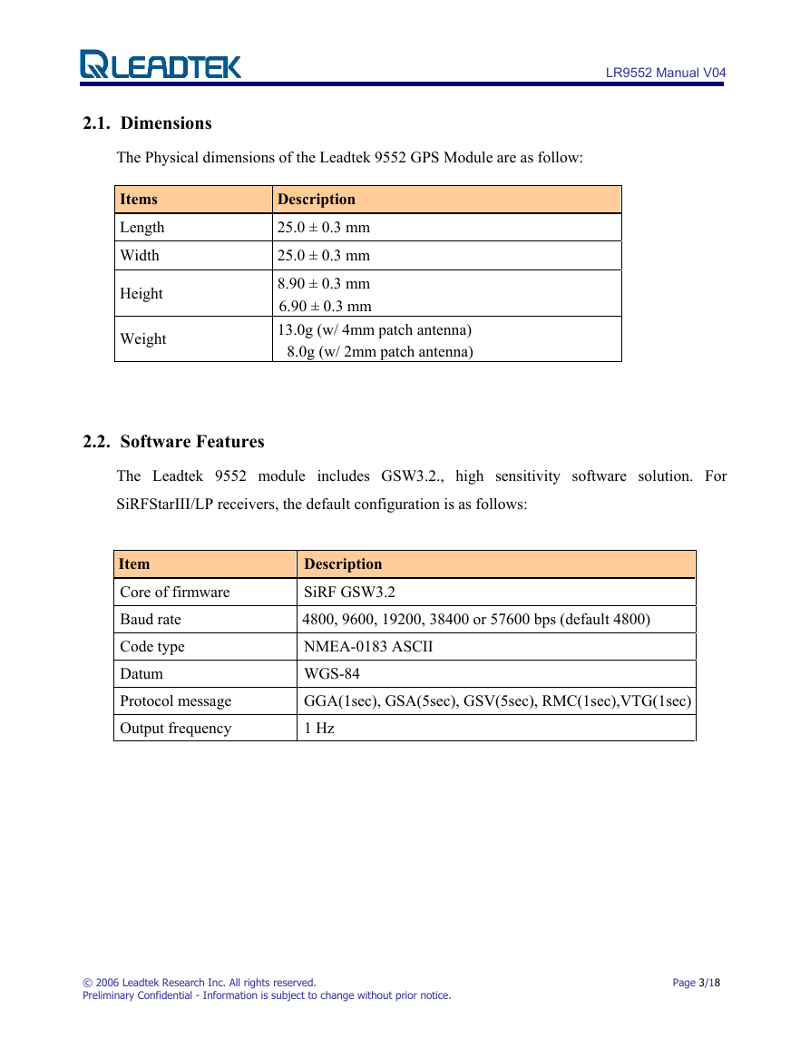
RoHS: This device complies with the Restr
enforce
o
d on 1st July 2006, saying all electr nic products sold in the EU
iction of Haza
rdous Substances (RoHS) directive that is
must with RoHS compliance.
© 2006 Leadtek Research Inc. All rights reserved.
Preliminary Confidential - Information is subject to change without prior notice.
Page 5/18
�
LR9552 Manual V04
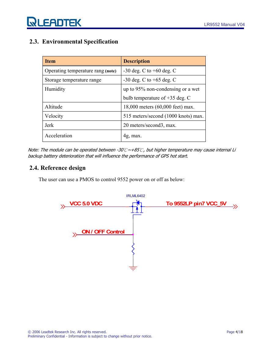
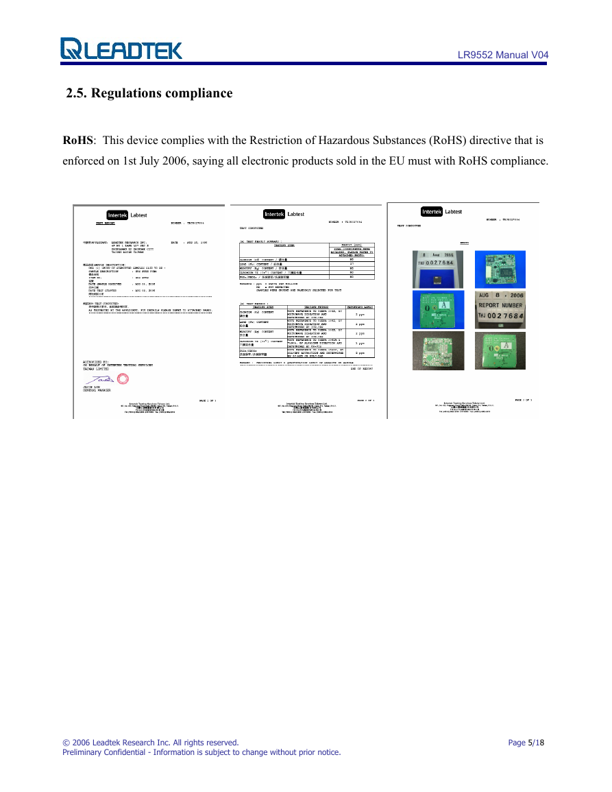
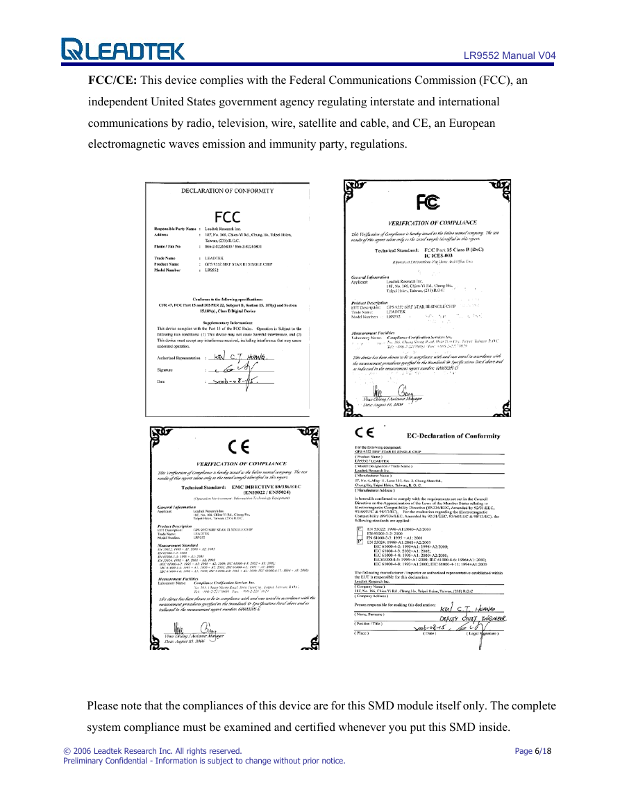
FCC/CE: This device complies with the Federal Communications Commission (FCC), an
rnment agency regulating interstate and international
independent United States gove
communications by radio, television, wire, satellite and cable, and CE, an European
electromagnetic waves emission and immunity party, regulations.
Please note that the compliances of this device are for this SMD module itself only. The complete
system compliance must be examined and certified whenever you put this SMD inside.
© 2006 Leadtek Research Inc. All rights reserved.
Preliminary Confidential - Information is subject to change without prior notice.
Page 6/18
�


 2023年江西萍乡中考道德与法治真题及答案.doc
 2012年重庆南川中考生物真题及答案.doc
 2013年江西师范大学地理学综合及文艺理论基础考研真题.doc
 2020年四川甘孜小升初语文真题及答案I卷.doc
 2020年注册岩土工程师专业基础考试真题及答案.doc
 2023-2024学年福建省厦门市九年级上学期数学月考试题及答案.doc
 2021-2022学年辽宁省沈阳市大东区九年级上学期语文期末试题及答案.doc
 2022-2023学年北京东城区初三第一学期物理期末试卷及答案.doc
 2018上半年江西教师资格初中地理学科知识与教学能力真题及答案.doc
 2012年河北国家公务员申论考试真题及答案-省级.doc
 2020-2021学年江苏省扬州市江都区邵樊片九年级上学期数学第一次质量检测试题及答案.doc
 2022下半年黑龙江教师资格证中学综合素质真题及答案.doc