High Speed Voltage Comparator
DD
when
when
A voltage comparator is an analog circuit that convert an analog signal to digital signal level.
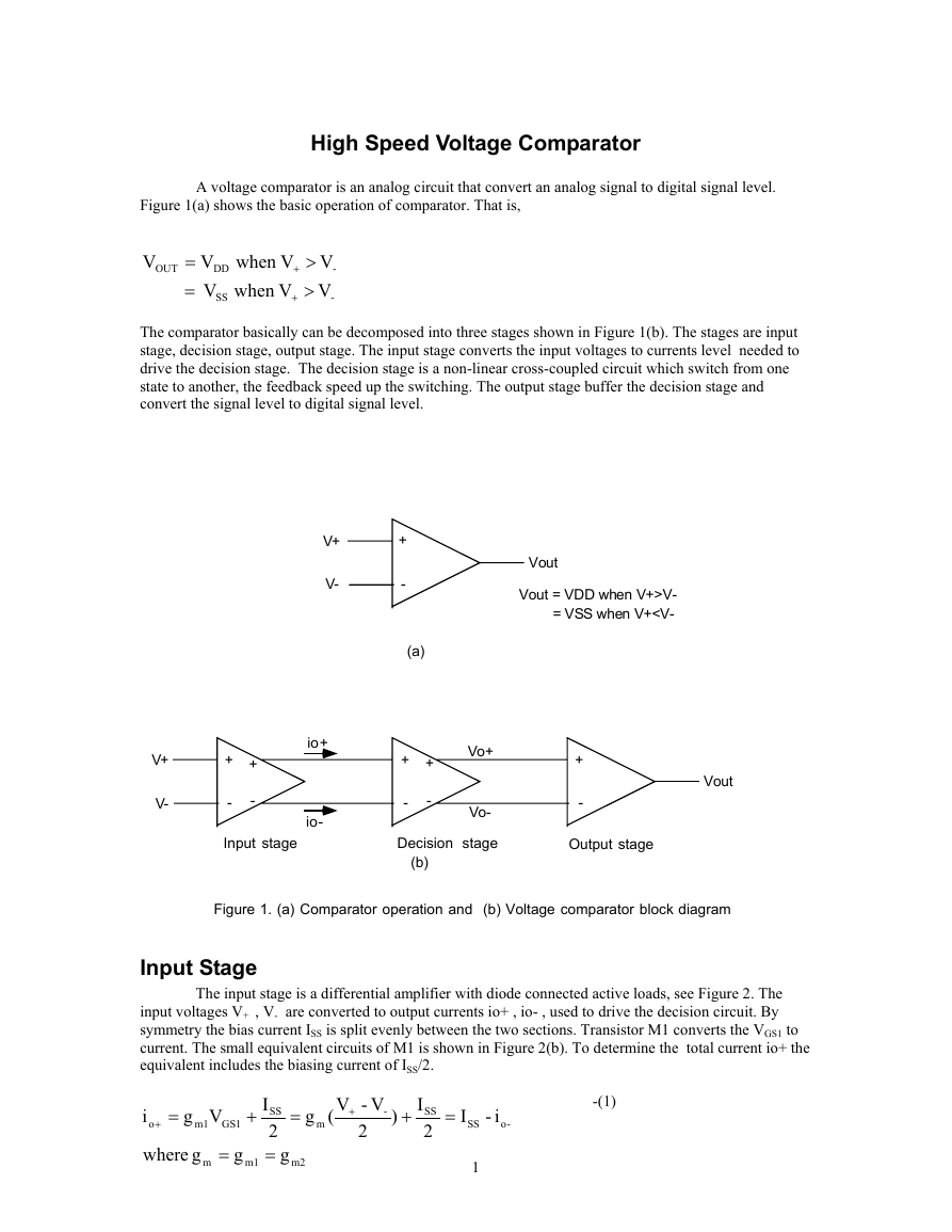
Figure 1(a) shows the basic operation of comparator. That is,
V
V
=
OUT
V
=
SS
The comparator basically can be decomposed into three stages shown in Figure 1(b). The stages are input
stage, decision stage, output stage. The input stage converts the input voltages to currents level needed to
drive the decision stage. The decision stage is a non-linear cross-coupled circuit which switch from one
state to another, the feedback speed up the switching. The output stage buffer the decision stage and
convert the signal level to digital signal level.
V
V
>
-
+
V
V
>
-
+
V+
V-
+
-
(a)
Vout
Vout = VDD when V+>V-
= VSS when V+
M31
M3
io-
M41
io+
M4
M1
M2
v+ + v-
2
v+
v+ - v-
2
v-
io+
io-
ISS
(a)
io+
ISS
2
gm1VGS1
=
gm1
2 (V+ - V-)
(b)
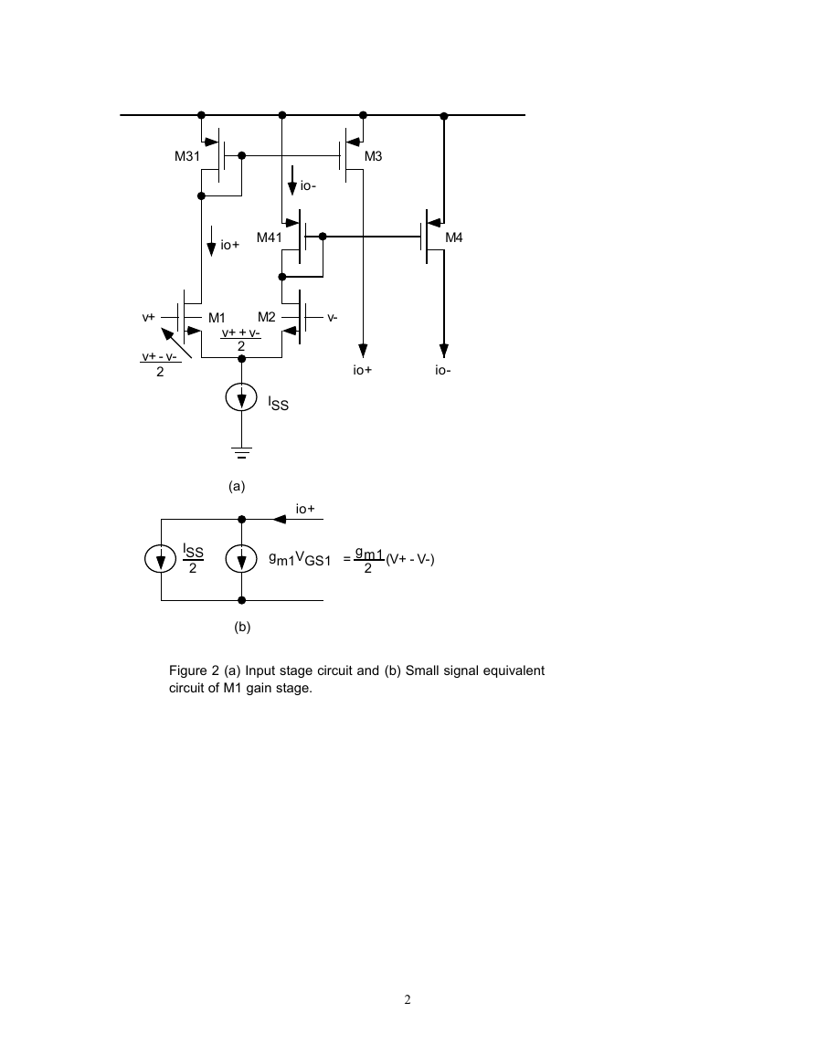
Figure 2 (a) Input stage circuit and (b) Small signal equivalent
circuit of M1 gain stage.
2
�
Decision stage
io+
io-
vo+
vo+
vo+
vo-
vo-
vo-
M5 M6
M7 M8
(a)
io+
io-
M5 M6
M7 M8
(b)
io+
io-
M5 M6
M7 M8
(c)
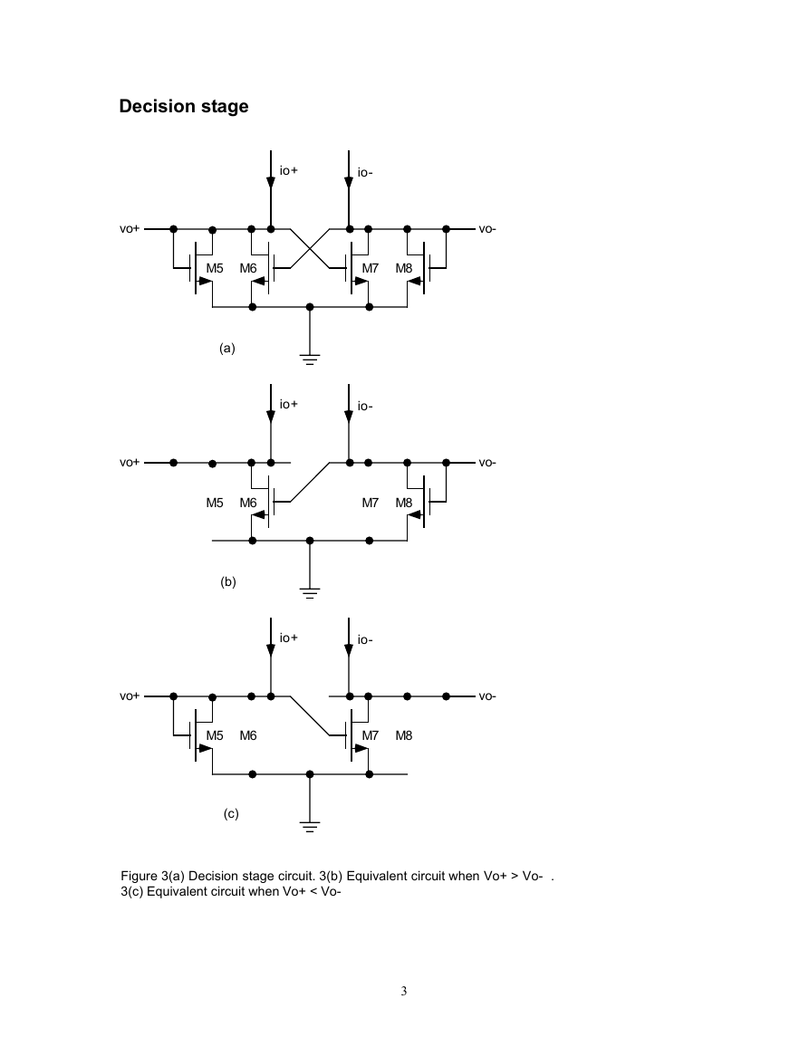
Figure 3(a) Decision stage circuit. 3(b) Equivalent circuit when Vo+ > Vo- .
3(c) Equivalent circuit when Vo+ < Vo-
3
�
o
-o
The decision circuit is a bistable cross coupled circuit shown in Figure 3(a). It is in one state or
=
=
i
8
i
off
is M7 , 0 i
7
is M5 , 0 i
off
5
bias
current
constant
since
;
i
i
=
+
=
8
7
i
i
;
since
=
+
=
6
5
6
+
i
I ;
I
=
+
=
B
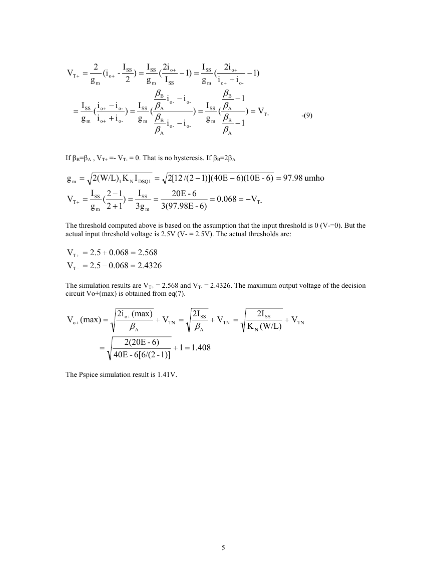
another. The state is determined by the magnitude of the input currents. If io- >> io+ M6 and M8 are on and
M5 and M7 are off. Figure 3(b) shows the following conditions hold:
i
i
i
Under these conditions, Vo+ = VDS6≈ 0 (M6 is on) and Vo- is determined by the value of VGS8 when i8=io- .
That is,
i
)V-V(
TN
)V-V(
TN
-(2)
=
=
=
-o
-o
i
B
+
2
o
2
β
8
2
=
-o
8
where
βββ
8
GS8
=
A
5
β
A
2
-(3)
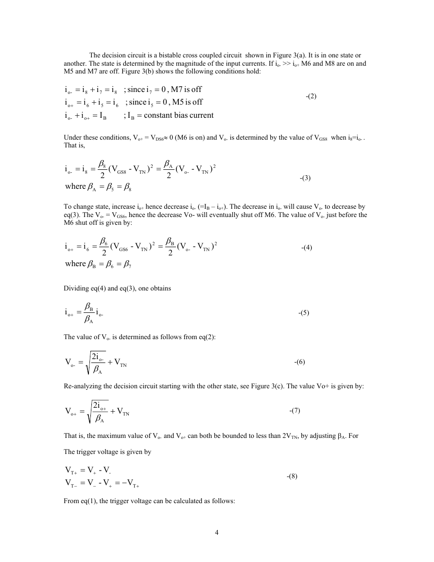
To change state, increase io+ hence decrease io- (=IB – io+). The decrease in io- will cause Vo- to decrease by
eq(3). The Vo- = VGS6, hence the decrease Vo- will eventually shut off M6. The value of Vo- just before the
M6 shut off is given by:
i
)V-V(
TN
-(4)
=
=
i
2
2
β
B
2
)V-V(
TN
-o
=+
o
6
where
βββ
7
GS6
=
B
6
β
6
2
=
Dividing eq(4) and eq(3), one obtains
i
i
=+
o
-o
β
B
β
A
The value of Vo- is determined as follows from eq(2):
V
-o
=
2i
-o
β
A
TN
+
V
-(5)
-(6)
Re-analyzing the decision circuit starting with the other state, see Figure 3(c). The value Vo+ is given by:
V
o
+
=
+
2i
o
β
A
TN
+
V
-(7)
That is, the maximum value of Vo- and Vo+ can both be bounded to less than 2VTN, by adjusting βA. For
The trigger voltage is given by
V
T
V
T
From eq(1), the trigger voltage can be calculated as follows:
V-V
-
V-V
+
−=
-(8)
V
T
=
=
+
−
+
−
+
4
�
V
T
=
+
2
g
m
i(
o
+
-
I
SS
2
)
=
I
SS
g
(
i2
I
SS
o
+
−
)1
=
I
SS
g
m
(
i
m
β
B
β
A
β
B
β
A
(
i
i
−
i
-o
-o
−
i
-o
-o
)
=
I
SS
g
m
i2
o
+
o
+
β
B
β
A
β
B
β
A
(
+
i
-o
−
1
−
1
−
)1
V)
=
-T
-(9)
=
I
SS
g
m
(
i
i
o
+
o
+
−
+
i
i
-o
-o
)
=
I
SS
g
m
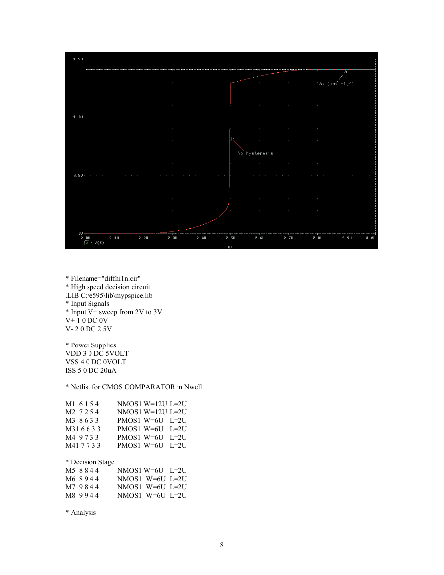
If βB=βA , VT+ =- VT- = 0. That is no hysteresis. If βB=2βA
g
=
=
IK
N
m
2(W/L)
1
I
12(
−
SS
12
g
+
m
)
=
DSQ1
I
SS
3g
m
=
)](12/(12[2
−
6-E20
3(97.98E
-
6)
=
V
T
+
=
068.0
−=
V
-T
-E10)(6E40
−
6)
=
98.97
umho
+
The threshold computed above is based on the assumption that the input threshold is 0 (V-=0). But the
actual input threshold voltage is 2.5V (V- = 2.5V). The actual thresholds are:
V
T
V
T
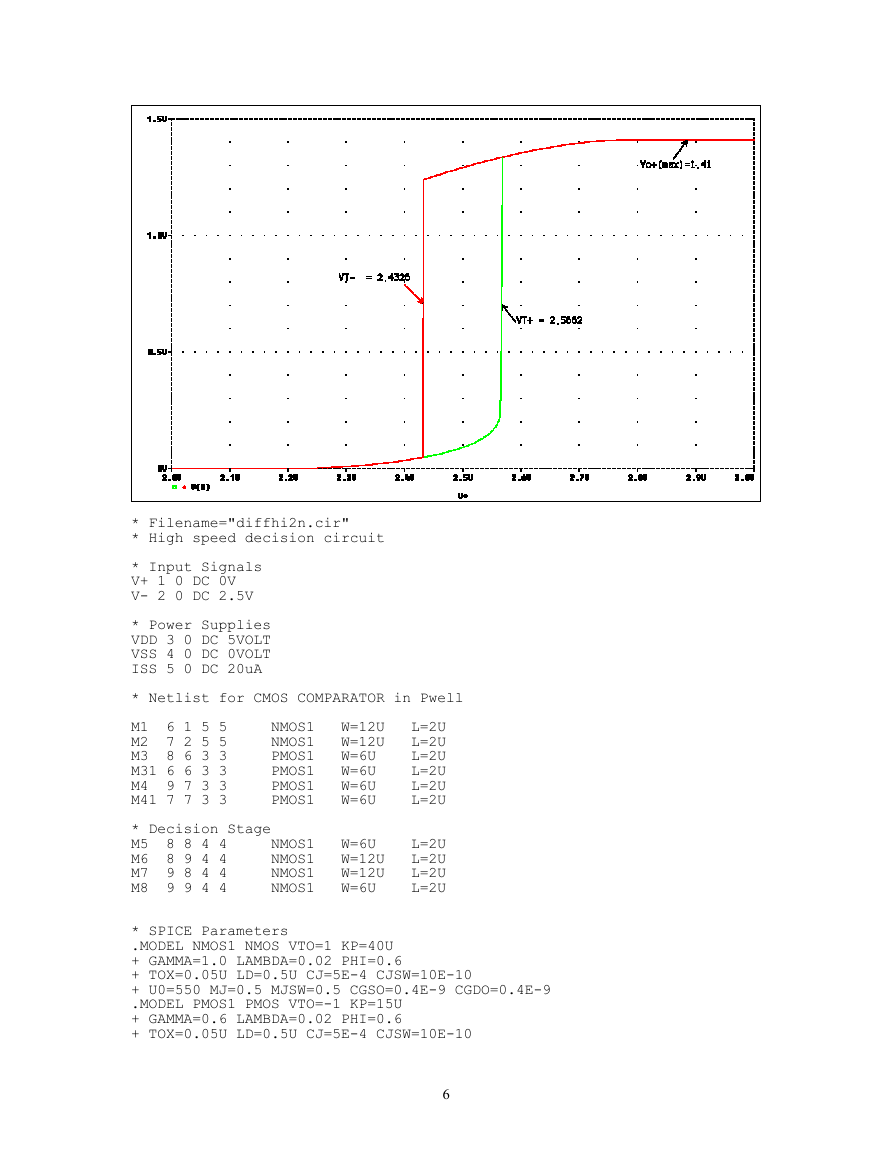
The simulation results are VT+ = 2.568 and VT- = 2.4326. The maximum output voltage of the decision
circuit Vo+(max) is obtained from eq(7).
2.568
2.4326
0.068
0.068
2.5
+
2.5
−
=
=
=
=
−
(V
+
o
max)
=
2i
=
o
(max)
+
β
A
2(20E
6)
-
6[6/(2
-
-E40
408.11
=+
1)]
+
V
TN
=
2I
SS
β
A
+
V
TN
=
2I
SS
(W/L)
N
K
+
V
TN
The Pspice simulation result is 1.41V.
5
�
* Filename="diffhi2n.cir"
* High speed decision circuit
* Input Signals
V+ 1 0 DC 0V
V- 2 0 DC 2.5V
* Power Supplies
VDD 3 0 DC 5VOLT
VSS 4 0 DC 0VOLT
ISS 5 0 DC 20uA
* Netlist for CMOS COMPARATOR in Pwell
M1 6 1 5 5
M2 7 2 5 5
M3 8 6 3 3
M31 6 6 3 3
M4 9 7 3 3
M41 7 7 3 3
* Decision Stage
M5 8 8 4 4 NMOS1 W=6U L=2U
M6 8 9 4 4 NMOS1 W=12U L=2U
NMOS1 W=12U L=2U
M7 9 8 4 4
M8 9 9 4 4
NMOS1 W=6U
L=2U
* SPICE Parameters
.MODEL NMOS1 NMOS VTO=1 KP=40U
+ GAMMA=1.0 LAMBDA=0.02 PHI=0.6
+ TOX=0.05U LD=0.5U CJ=5E-4 CJSW=10E-10
+ U0=550 MJ=0.5 MJSW=0.5 CGSO=0.4E-9 CGDO=0.4E-9
.MODEL PMOS1 PMOS VTO=-1 KP=15U
+ GAMMA=0.6 LAMBDA=0.02 PHI=0.6
+ TOX=0.05U LD=0.5U CJ=5E-4 CJSW=10E-10
NMOS1 W=12U L=2U
NMOS1 W=12U L=2U
L=2U
PMOS1 W=6U
PMOS1 W=6U
L=2U
L=2U
PMOS1 W=6U
PMOS1 W=6U
L=2U
6
�
NMOS1 W=12U L=2U
NMOS1 W=12U L=2U
PMOS1 W=6U
L=2U
L=2U
PMOS1 W=6U
L=2U
PMOS1 W=6U
PMOS1 W=6U
L=2U
+ U0=200 MJ=0.5 MJSW=0.5 CGSO=0.4E-9 CGDO=0.4E-9
* Analysis
.DC V+ 2V 3V 1mV
.PROBE
.END
* Filename="diffhi2n.cir"
* High speed decision circuit
* Input Signals
V+ 1 0 DC 0V
V- 2 0 DC 2.5V
* Power Supplies
VDD 3 0 DC 5VOLT
VSS 4 0 DC 0VOLT
ISS 5 0 DC 20uA
* Netlist for CMOS COMPARATOR in Pwell
M1 6 1 5 5
M2 7 2 5 5
M3 8 6 3 3
M31 6 6 3 3
M4 9 7 3 3
M41 7 7 3 3
* Decision Stage
M5 8 8 4 4 NMOS1 W=6U L=2U
M6 8 9 4 4 NMOS1 W=12U L=2U
NMOS1 W=12U L=2U
M7 9 8 4 4
M8 9 9 4 4
NMOS1 W=6U
L=2U
* SPICE Parameters
.MODEL NMOS1 NMOS VTO=1 KP=40U
+ GAMMA=1.0 LAMBDA=0.02 PHI=0.6
+ TOX=0.05U LD=0.5U CJ=5E-4 CJSW=10E-10
+ U0=550 MJ=0.5 MJSW=0.5 CGSO=0.4E-9 CGDO=0.4E-9
.MODEL PMOS1 PMOS VTO=-1 KP=15U
+ GAMMA=0.6 LAMBDA=0.02 PHI=0.6
+ TOX=0.05U LD=0.5U CJ=5E-4 CJSW=10E-10
+ U0=200 MJ=0.5 MJSW=0.5 CGSO=0.4E-9 CGDO=0.4E-9
* Analysis
.DC V+ 3V 2V -1mV
*.TRAN .1ns 40us
.PROBE
.END
7
�
* Filename="diffhi1n.cir"
* High speed decision circuit
.LIB C:\e595\lib\mypspice.lib
* Input Signals
* Input V+ sweep from 2V to 3V
V+ 1 0 DC 0V
V- 2 0 DC 2.5V
* Power Supplies
VDD 3 0 DC 5VOLT
VSS 4 0 DC 0VOLT
ISS 5 0 DC 20uA
* Netlist for CMOS COMPARATOR in Nwell
M1 6 1 5 4
M2 7 2 5 4
M3 8 6 3 3
M31 6 6 3 3
M4 9 7 3 3
M41 7 7 3 3
* Decision Stage
M5 8 8 4 4
M6 8 9 4 4
M7 9 8 4 4
M8 9 9 4 4
* Analysis
NMOS1 W=12U L=2U
NMOS1 W=12U L=2U
PMOS1 W=6U L=2U
PMOS1 W=6U L=2U
PMOS1 W=6U L=2U
PMOS1 W=6U L=2U
NMOS1 W=6U L=2U
NMOS1 W=6U L=2U
NMOS1 W=6U L=2U
NMOS1 W=6U L=2U
8
�


 2023年江西萍乡中考道德与法治真题及答案.doc
 2012年重庆南川中考生物真题及答案.doc
 2013年江西师范大学地理学综合及文艺理论基础考研真题.doc
 2020年四川甘孜小升初语文真题及答案I卷.doc
 2020年注册岩土工程师专业基础考试真题及答案.doc
 2023-2024学年福建省厦门市九年级上学期数学月考试题及答案.doc
 2021-2022学年辽宁省沈阳市大东区九年级上学期语文期末试题及答案.doc
 2022-2023学年北京东城区初三第一学期物理期末试卷及答案.doc
 2018上半年江西教师资格初中地理学科知识与教学能力真题及答案.doc
 2012年河北国家公务员申论考试真题及答案-省级.doc
 2020-2021学年江苏省扬州市江都区邵樊片九年级上学期数学第一次质量检测试题及答案.doc
 2022下半年黑龙江教师资格证中学综合素质真题及答案.doc