logo资料库

PN532用户手册中文版.pdf

第1页 / 共200页
第2页 / 共200页
第3页 / 共200页
第4页 / 共200页
第5页 / 共200页
第6页 / 共200页
第7页 / 共200页
第8页 / 共200页
资料共200页,剩余部分请下载后查看
1. Introduction
1.1 Purpose and Scope
1.2 Intended audience
1.3 Glossary
1.4 References
1.5 General presentation of the PN532
2. Configuration Modes
2.1 Standard Mode
2.2 PN512 emulation mode
2.3 RFfieldON Mode
3. Power management
3.1.1 CPU frequency
3.1.2 Power modes of the PN532
3.1.2.1 Power modes for CPU
3.1.2.2 Power modes for Contact Less interface
3.1.3 Operating modes of the PN532
3.1.3.1 Mode dispatcher
3.1.3.2 Standby mode
3.1.3.3 LowVbat mode
3.1.3.4 Initiator / PCD mode
3.1.3.5 Target / PICC Mode
3.1.3.6 Virtual Card mode
3.1.3.7 Wired Card mode
3.1.3.8 Initialization sequence
3.1.3.9 Management of GPIO configuration
3.1.3.10 Management of RF field in the activation commands
4. ISO/IEC14443-4 PICC emulation concept
5. Over-current detection
6. Host controller Interfaces
6.1 General points
6.1.1 Possible links
6.1.1.1 SPI interface
6.1.1.2 HSU interface
6.1.1.3 I2C interface
6.1.2 P70_IRQ pin
6.2 Host controller communication protocol
6.2.1 Frames structure
6.2.1.1 Normal information frame
6.2.1.2 Extended information frame
6.2.1.3 ACK frame
6.2.1.4 NACK frame
6.2.1.5 Error frame
6.2.1.6 Preamble and Postamble
6.2.2 Dialog structure
6.2.2.1 Data link level
6.2.2.2 Application level
6.2.3 HSU communication details
6.2.4 I2C communication details
6.2.4.1 Classic I2C communication (without Handshake mechanism combination)
6.2.4.2 Advanced I2C communication (with Handshake mechanism combination)
6.2.5 SPI communication details
6.2.5.1 Classic SPI communication (without Handshake mechanism combination)
6.2.5.2 Advanced SPI communication (with Handshake mechanism combination)
6.3 Handshake mechanism
6.3.1 General presentation
6.3.2 Handshake mechanism in case of HSU link
6.3.2.1 Case of LowVbat
6.3.2.2 Normal case
6.3.2.3 Case of PN532 in Power Down mode
6.3.2.4 Case of the TgInitAsTarget command
6.3.2.5 Case of SAMConfiguration – Virtual Card
6.3.3 Handshake mechanism in case of I2C link
6.3.3.1 Case of LowVbat
6.3.3.2 Normal case
6.3.3.3 Case of PN532 in Power Down mode
6.3.3.4 Case of the TgInitAsTarget command
6.3.3.5 Case of SAMConfiguration – Virtual Card
6.3.4 Handshake mechanism in case of SPI link
6.3.4.1 Case of LowVbat
6.3.4.2 Normal case
6.3.4.3 Case of PN532 in Power Down mode
6.3.4.4 Case of the TgInitAsTarget Command
6.3.4.5 Case of SAMConfiguration – Virtual Card
7. Commands supported
7.1 Error handling
7.2 Miscellaneous commands
7.2.1 Diagnose
7.2.2 GetFirmwareVersion
7.2.3 GetGeneralStatus
7.2.4 ReadRegister
7.2.5 WriteRegister
7.2.6 ReadGPIO
7.2.7 WriteGPIO
7.2.8 SetSerialBaudRate
7.2.9 SetParameters
7.2.10 SAMConfiguration
7.2.11 PowerDown
7.3 RF Communication command
7.3.1 RFConfiguration
7.3.2 RFRegulationTest
7.3.3 InJumpForDEP
7.3.4 InJumpForPSL
7.3.5 InListPassiveTarget
7.3.6 InATR
7.3.7 InPSL
7.3.8 InDataExchange
7.3.9 InCommunicateThru
7.3.10 InDeselect
7.3.11 InRelease
7.3.12 InSelect
7.3.13 InAutoPoll
7.3.14 TgInitAsTarget
7.3.15 TgSetGeneralBytes
7.3.16 TgGetData
7.3.17 TgSetData
7.3.18 TgSetMetaData
7.3.19 TgGetInitiatorCommand
7.3.20 TgResponseToInitiator
7.3.21 TgGetTargetStatus
7.4 Commands summary
7.4.1 Commands for Initiator mode
7.4.2 Commands for Target mode
7.4.3 Commands for ISO/IEC14443-4 PICC mode
7.4.4 Target states summary
7.4.5 DEP chaining mechanism
7.4.6 ISO/IEC14443-4 PICC emulated chaining mechanism
7.4.7 Comparison of the length of Payload data field
7.5 Examples of use
7.5.1 PN532 acting as Mifare PCD
7.5.2 PN532 acting as FeliCa PCD
7.5.3 PN532 acting as 106 kbps target
7.5.4 PN532 acting as 212 kbps target
7.5.5 Peer to Peer example with two PN532 (passive mode)
7.5.6 Peer to Peer example with two PN532 (active mode)
8. Appendix
8.1 Command set
9. Legal information
9.1 Definitions
9.2 Disclaimers
9.3 Licenses
9.4 Patents
9.5 Trademarks
10. Tables
11. Figures
12. Contents
UM0701-02 PN532 User Manual Rev. 02 User Manual Document information Info Content Keywords Abstract NFC, PN532, V1.6 This document describes the firmware V1.6 embedded in the PN532.
UM0701-02 PN532 User Manual NXP Semiconductors Revision history Initial version for firmware version V1.5 (PN532/C105) Version for firmware version V1.6 (PN532/C106) 01 02 2007-04-27 2007-11-05 Contact information For additional information, please visit: http://www.nxp.com For sales office addresses, please send an email to: sales.addresses@www.nxp.com UM0701-02 User Manual Rev. 02 - 5th November 2007 © NXP B.V. 2007. All rights reserved. 2 of 200
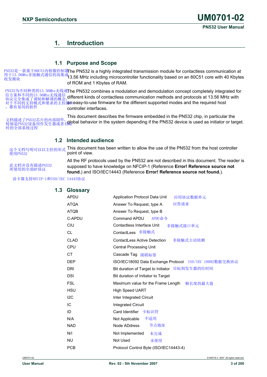
NXP Semiconductors 1. Introduction 1.1 Purpose and Scope UM0701-02 PN532 User Manual The PN532 is a highly integrated transmission module for contactless communication at 13.56 MHz including microcontroller functionality based on an 80C51 core with 40 Kbytes of ROM and 1 Kbytes of RAM. The PN532 combines a modulation and demodulation concept completely integrated for different kinds of contactless communication methods and protocols at 13.56 MHz with an easy-to-use firmware for the different supported modes and the required host controller interfaces. This document describes the firmware embedded in the PN532 chip, in particular the global behavior in the system depending if the PN532 device is used as initiator or target. Intended audience This document has been written to allow the use of the PN532 from the host controller point of view. All the RF protocols used by the PN532 are not described in this document. The reader is supposed to have knowledge on NFCIP-1 (Reference Error! Reference source not found.) and ISO/IEC14443 (Reference Error! Reference source not found.). 1.2 1.3 Glossary APDU ATQA ATQB C-APDU CIU CL CLAD CPU CT DEP DRI DSI FSL HSU I2C IC ID N/A NAD N/I NU PCB UM0701-02 User Manual Application Protocol Data Unit Answer To Request, type A Answer To Request, type B Command APDU Contactless Interface Unit ContactLess ContactLess Active Detection Central Processing Unit Cascade Tag ISO/IEC18092 Data Exchange Protocol Bit duration of Target to Initiator Bit duration of Initiator to Target Maximum value for the Frame Length High Speed UART Inter Integrated Circuit Integrated Circuit Card Identifier Not Applicable Node ADdress Not Implemented Not Used Protocol Control Byte (ISO/IEC14443-4) Rev. 02 - 5th November 2007 © NXP B.V. 2007. All rights reserved. 3 of 200
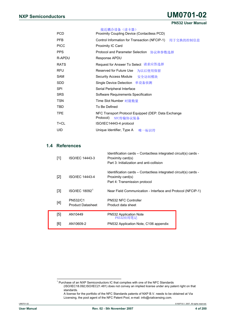
NXP Semiconductors UM0701-02 PN532 User Manual PCD PFB PICC PPS R-APDU RATS RFU SAM SDD SPI SRS TSN TBD TPE T=CL UID Proximity Coupling Device (Contactless PCD) Control Information for Transaction (NFCIP-1) Proximity IC Card Protocol and Parameter Selection Response APDU Request for Answer To Select Reserved for Future Use Security Access Module Single Device Detection Serial Peripheral Interface Software Requirements Specification Time Slot Number To Be Defined NFC Transport Protocol Equipped (DEP: Data Exchange Protocol) ISO/IEC14443-4 protocol Unique Identifier, Type A 1.4 References [1] ISO/IEC 14443-3 Identification cards – Contactless integrated circuit(s) cards - Proximity card(s) Part 3: Initialization and anti-collision ISO/IEC 14443-4 Identification cards – Contactless integrated circuit(s) cards - Proximity card(s) Part 4: Transmission protocol ISO/IEC 180921 Near Field Communication - Interface and Protocol (NFCIP-1) PN532/C1 Product Datasheet PN532 NFC Controller Product data sheet AN10449 PN532 Application Note AN10609-2 PN532 Application Note, C106 appendix [2] [3] [4] [5] [6] 1 Purchase of an NXP Semiconductors IC that complies with one of the NFC Standards (ISO/IEC18.092;ISO/IEC21.481) does not convey an implied license under any patent right on that standards. A license for the portfolio of the NFC Standards patents of NXP B.V. needs to be obtained at Via Licensing, the pool agent of the NFC Patent Pool, e-mail: info@vialicensing.com. UM0701-02 User Manual Rev. 02 - 5th November 2007 © NXP B.V. 2007. All rights reserved. 4 of 200
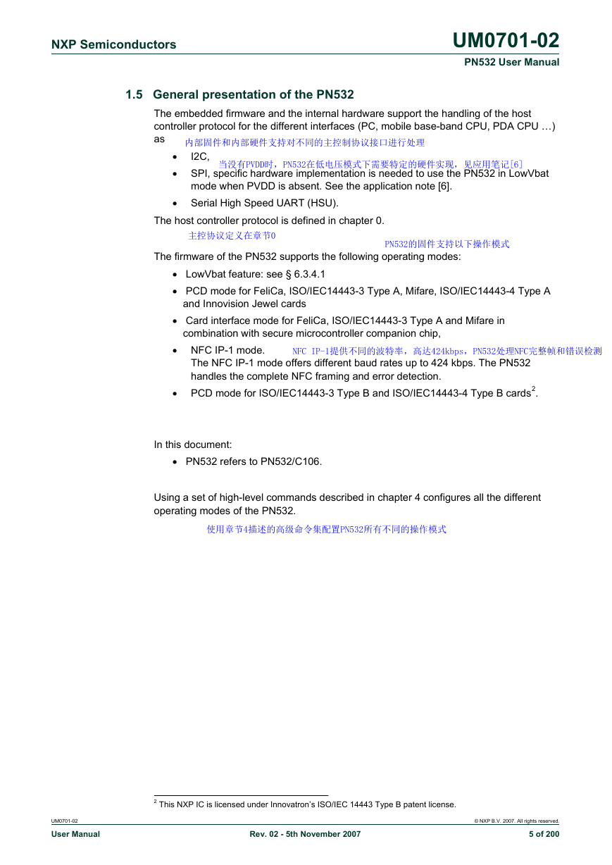
NXP Semiconductors UM0701-02 PN532 User Manual 1.5 General presentation of the PN532 The embedded firmware and the internal hardware support the handling of the host controller protocol for the different interfaces (PC, mobile base-band CPU, PDA CPU …) as I2C, • • SPI, specific hardware implementation is needed to use the PN532 in LowVbat mode when PVDD is absent. See the application note [6]. • Serial High Speed UART (HSU). The host controller protocol is defined in chapter 0. The firmware of the PN532 supports the following operating modes: • LowVbat feature: see § 6.3.4.1 • PCD mode for FeliCa, ISO/IEC14443-3 Type A, Mifare, ISO/IEC14443-4 Type A and Innovision Jewel cards • Card interface mode for FeliCa, ISO/IEC14443-3 Type A and Mifare in combination with secure microcontroller companion chip, • NFC IP-1 mode. The NFC IP-1 mode offers different baud rates up to 424 kbps. The PN532 handles the complete NFC framing and error detection. • PCD mode for ISO/IEC14443-3 Type B and ISO/IEC14443-4 Type B cards2. In this document: • PN532 refers to PN532/C106. Using a set of high-level commands described in chapter 4 configures all the different operating modes of the PN532. UM0701-02 User Manual 2 This NXP IC is licensed under Innovatron’s ISO/IEC 14443 Type B patent license. Rev. 02 - 5th November 2007 © NXP B.V. 2007. All rights reserved. 5 of 200
NXP Semiconductors UM0701-02 PN532 User Manual 2. Configuration Modes The PN532 has 3 possible modes that can be chosen by using two GPIOs during the reset phase of the IC: Table 1. Configuration modes Mode Standard PN512 emulation RF field ON 2.1 Standard Mode Selection Pins P70_IRQ (pin #25) P35 (pin #19) 1 0 1 0 1 1 0 0 This is the default mode of the PN532. The description of this mode is detailed in this document starting from chapter 0. 2.2 PN512 emulation mode In this test mode, the PN532 is configured to act as real PN512 IC using serial interface. The PN512 is a transmission module for contactless communication at 13.56 MHz. It integrates a modulation and demodulation concept for different kind of contactless communication methods and protocols. Then, the PN532 can be easily interfaced with the PN512 dedicated host controller software, as e.g. Joiner PC Serial. The link used is RS232 at 9600 bauds3. It is not possible to change the value of the baud rate; the SerialSpeedReg register is not emulated. The emulation of the PN512 IRQ pin is supported as well; the pin used is P70_IRQ. The level of the P70_IRQ pin is low when an interrupt occurs. The bit IRQInv in the register CIU_CommIEnReg has no effect (see Error! Reference source not found.). 3 The RS232 link used here is the standard UART, not the High Speed UART. Consequently, in this mode the PN532 must be interconnected with P30 (pin#24) for the HSU_RX line and P31 (pin#31) for the HSU_TX line. UM0701-02 User Manual Rev. 02 - 5th November 2007 © NXP B.V. 2007. All rights reserved. 6 of 200
NXP Semiconductors 2.3 RFfieldON Mode UM0701-02 PN532 User Manual In this mode, the PN532 is configured to switch on its RF field immediately after the reset. The modulation and the baud rate used depend on the selection GPIOs P33_INT1 and P34/SIC_CLK and random data bytes are continuously sent. In this mode, the temperature sensor is not activated, so that tests can be done at temperature higher than 125°C. TX framing and TX speed in RFfieldON configuration Table 2. TX framing – TX speed Mifare - 106 kbps FeliCa - 212 kbps FeliCa - 424 kbps Selection Pins P33_INT1 (pin #33) P34/SIC_CLK (pin #34) 1 0 0 1 1 0 1 0 UM0701-02 User Manual Rev. 02 - 5th November 2007 © NXP B.V. 2007. All rights reserved. 7 of 200
NXP Semiconductors UM0701-02 PN532 User Manual 3. Power management The PN532 is dedicated for mobile equipments, where the power consumption is a very important parameter. The design of the firmware embedded in the PN532 takes care of that, in a sense that it minimizes the overall power consumption. This chapter defines the strategy used to save current consumption. The firmware can play with different parameters described hereafter: • CPU frequency, • Power modes of the CPU, • Power modes of the CL front-end, • Management of pin configuration. UM0701-02 User Manual Rev. 02 - 5th November 2007 © NXP B.V. 2007. All rights reserved. 8 of 200
分享到:
收藏