大家好,欢迎来到 TI Precision Labs(德州仪器高精度实验室)。本节视频的主题是
input offset voltage (输入电压偏移误差)Vos,和 input bias current (输入偏置电
流)Ib。我们将会学习运放 Vos 参数,Vos drift over temperature(电压漂移误差),
Ib 的参数,以及 input bias current drift over temperature(输入漂移电流)。同时我
们也会给出 TI 不同运算放大器 Vos 和 Ib 的范围。
Hello, and welcome to the TI Precision Lab discussing input offset voltage, VOS,
In this video we’ll discuss op amp VOS specifications,
and input bias current, IB.
VOS drift over temperature, input bias current specifications, and input bias
current drift over temperature. We’ll also show the range of VOS and IB across
many different Texas Instruments op amps.
�
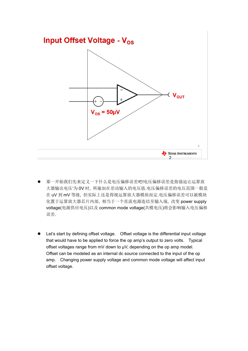
那一开始我们先来定义一下什么是电压偏移误差吧!电压偏移误差是指强迫让运算放
大器输出电压‘为 0V 时, 所施加在差动输入的电压值.电压偏移误差的电压范围一般是
在 uV 到 mV 等级, 但实际上还是得视运算放大器模块而定.电压偏移误差可以被模块
化置于运算放大器芯片内部, 相当于一个直流电源连结至输入端, 改变 power supply
voltage(电源供应电压)以及 common mode voltage(共模电压)将会影响输入电压偏移
误差.
Let’s start by defining offset voltage. Offset voltage is the differential input voltage
that would have to be applied to force the op amp’s output to zero volts. Typical
offset voltages range from mV down to μV, depending on the op amp model.
Offset can be modeled as an internal dc source connected to the input of the op
amp. Changing power supply voltage and common mode voltage will affect input
offset voltage.
�
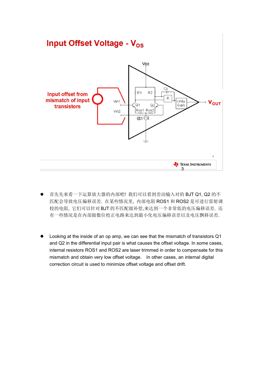
首先先来看一下运算放大器的内部吧! 我们可以看到差动输入对的 BJT Q1, Q2 的不
匹配会导致电压偏移误差. 在某些情况里, 内部电阻 ROS1 和 ROS2 是可进行雷射调
校的电阻, 它们可以针对 BJT 的不匹配做补偿,来达到一个非常低的电压偏移误差. 还
有一些情况是在内部做数位校正电路来达到最小化电压偏移误差以及电压飘移误差.
Looking at the inside of an op amp, we can see that the mismatch of transistors Q1
and Q2 in the differential input pair is what causes the offset voltage. In some cases,
internal resistors ROS1 and ROS2 are laser trimmed in order to compensate for this
mismatch and obtain very low offset voltage.
correction circuit is used to minimize offset voltage and offset drift.
In other cases, an internal digital
�
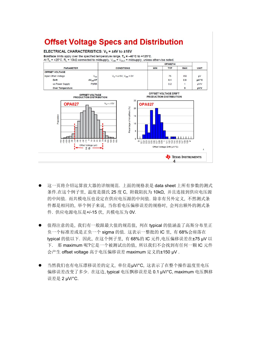
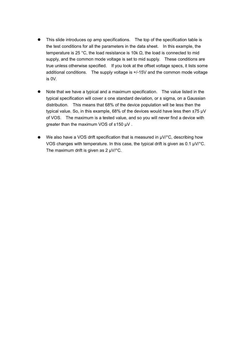
这一页将介绍运算放大器的详细规范. 上面的规格表是 data sheet 上所有参数的测式
条件.在这个例子里, 温度是摄氏 25 度 C, 附载阻抗为 10kΩ, 并且连接到供应电压源
的中间值. 而共模电压也设定在供应电压源的中间值. 除非有另外定义, 不然测式条
件都是相同的, 举个例子来说, 当你看电压偏移误差的规格时, 会列出额外的测式条
件. 供应电源电压是+/-15 伏, 共模电压为 0V.
值得注意的是, 我们有一般跟最大值的规范值, 列在 typical 的值涵盖了高斯分布里正
负一个标准差或是正负一个 sigma 的值. 这表示一整批的 IC 里, 有 68%会座落在
typical 的值以下. 因此, 在这个例子里, 有 68%的 IC 元件,电压偏移误差在±75 μV 以
下. 那 maximum 呢?它是一个被测试出的值, 所以我们不会找到有任何一颗 IC 元件
会产生 offset voltage 高于电压偏移误差 maximum 定义的±150 μV .
当然我们也有电压漂移误差的定义, 单位是μV/°C, 这表示了在整个操作温度里电压
偏移误差改变了多少. 在这边, typical 电压飘移误差是 0.1 μV/°C, maximum 电压飘移
误差是 2 μV/°C.
�
This slide introduces op amp specifications. The top of the specification table is
the test conditions for all the parameters in the data sheet.
In this example, the
temperature is 25 °C, the load resistance is 10k Ω, the load is connected to mid
supply, and the common mode voltage is set to mid supply. These conditions are
true unless otherwise specified.
If you look at the offset voltage specs, it lists some
additional conditions. The supply voltage is +/-15V and the common mode voltage
is 0V.
Note that we have a typical and a maximum specification. The value listed in the
typical specification will cover ± one standard deviation, or ± sigma, on a Gaussian
distribution. This means that 68% of the device population will be less then the
typical value. So, in this example, 68% of the devices would have less then ±75 μV
of VOS. The maximum is a tested value, and so you will never find a device with
greater than the maximum VOS of ±150 μV .
We also have a VOS drift specification that is measured in μV/°C, describing how
VOS changes with temperature. In this case, the typical drift is given as 0.1 μV/°C.
The maximum drift is given as 2 μV/°C.
�
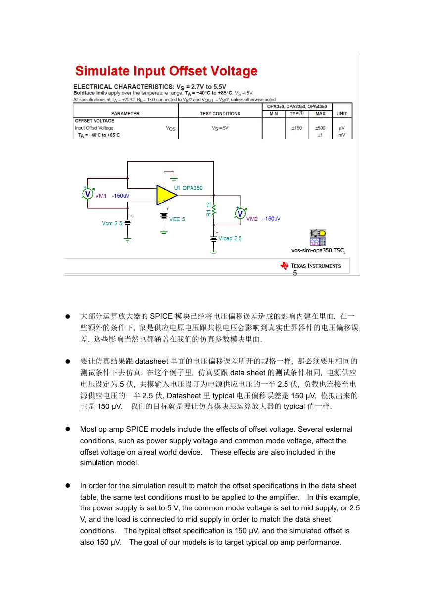
大部分运算放大器的 SPICE 模块已经将电压偏移误差造成的影响内建在里面. 在一
些额外的条件下, 象是供应电原电压跟共模电压会影响到真实世界器件的电压偏移误
差. 这些影响当然也都涵盖在我们的仿真参数模块里面.
要让仿真结果跟 datasheet 里面的电压偏移误差所开的规格一样, 那必须要用相同的
测试条件下去仿真. 在这个例子里, 仿真要跟 data sheet 的测试条件相同, 电源供应
电压设定为 5 伏, 共模输入电压设订为电源供应电压的一半 2.5 伏, 负载也连接至电
源供应电压的一半 2.5 伏. Datasheet 里 typical 电压偏移误差是 150 μV, 模拟出来的
也是 150 μV. 我们的目标就是要让仿真模块跟运算放大器的 typical 值一样.
Most op amp SPICE models include the effects of offset voltage. Several external
conditions, such as power supply voltage and common mode voltage, affect the
offset voltage on a real world device. These effects are also included in the
simulation model.
In order for the simulation result to match the offset specifications in the data sheet
table, the same test conditions must to be applied to the amplifier.
In this example,
the power supply is set to 5 V, the common mode voltage is set to mid supply, or 2.5
V, and the load is connected to mid supply in order to match the data sheet
conditions. The typical offset specification is 150 μV, and the simulated offset is
also 150 μV. The goal of our models is to target typical op amp performance.
�
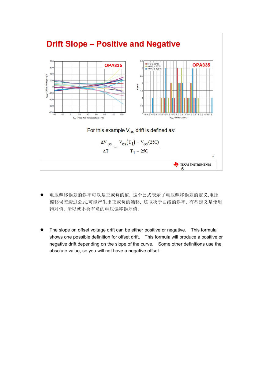
电压飘移误差的斜率可以是正或负的值. 这个公式表示了电压飘移误差的定义.电压
偏移误差透过公式,可能产生出正或负的漂移, 这取决于曲线的斜率. 有些定义是使用
绝对值, 所以就不会有负的电压偏移误差值.
The slope on offset voltage drift can be either positive or negative. This formula
shows one possible definition for offset drift. This formula will produce a positive or
negative drift depending on the slope of the curve. Some other definitions use the
absolute value, so you will not have a negative offset.
�
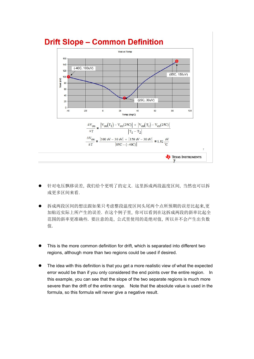
针对电压飘移误差, 我们给个更明了的定义. 这里拆成两段温度区间, 当然也可以拆
成更多区间来看.
拆成两段区间的想法跟如果只考虑整段温度区间头尾两个点所预期的误差比起来,更
加贴近实际上所产生的误差. 在这个例子里, 你可以看到在这拆成两段的斜率比起全
范围的斜率更准确些. 要注意的是, 公式里使用的是绝对值, 所以并不会产生出负数
值.
This is the more common definition for drift, which is separated into different two
regions, although more than two regions could be used if desired.
The idea with this definition is that you get a more realistic view of what the expected
error would be than if you only considered the end points over the entire region.
In
this example, you can see that the slope of the two separate regions is much more
severe than the drift of the entire range. Note that the absolute value is used in the
formula, so this formula will never give a negative result.
�


 2023年江西萍乡中考道德与法治真题及答案.doc
 2012年重庆南川中考生物真题及答案.doc
 2013年江西师范大学地理学综合及文艺理论基础考研真题.doc
 2020年四川甘孜小升初语文真题及答案I卷.doc
 2020年注册岩土工程师专业基础考试真题及答案.doc
 2023-2024学年福建省厦门市九年级上学期数学月考试题及答案.doc
 2021-2022学年辽宁省沈阳市大东区九年级上学期语文期末试题及答案.doc
 2022-2023学年北京东城区初三第一学期物理期末试卷及答案.doc
 2018上半年江西教师资格初中地理学科知识与教学能力真题及答案.doc
 2012年河北国家公务员申论考试真题及答案-省级.doc
 2020-2021学年江苏省扬州市江都区邵樊片九年级上学期数学第一次质量检测试题及答案.doc
 2022下半年黑龙江教师资格证中学综合素质真题及答案.doc