MIL-STD-1553
DESIGNER’S GUIDE
SIXTH EDITION
105 Wilbur Place
Bohemia, New York 11716-2482
TEL: (631) 567-5600 • FAX: (631) 567-7358
CUSTOMER SERVICE:
U.S.A. and Canada: 1-800-DDC-5757
International Direct: 1-631-567-5700
World Wide Web:
http://www.ddc-web.com
�
MIL-STD-1553 DESIGNER’S GUIDE
First Edition . . . . . . . . . . . . . . . . . . . . . . . . . . . . . . . . . . . . . . . . . . . . . . . . . . .(13,500) 1982
Second Printing
. . . . . . . . . . . . . . . . . . . . . . . . . . . . . . . . . . . . . . . . . . . . .(10,000) 1983
Third Printing . . . . . . . . . . . . . . . . . . . . . . . . . . . . . . . . . . . . . . . . . . . . . . .(10,000) 1984
Fourth Printing . . . . . . . . . . . . . . . . . . . . . . . . . . . . . . . . . . . . . . . . . . . . . .(10,000) 1986
Second Edition . . . . . . . . . . . . . . . . . . . . . . . . . . . . . . . . . . . . . . . . . . . . . . . . .(10,000) 1987
. . . . . . . . . . . . . . . . . . . . . . . . . . . . . . . . . . . . . . . . . . . . .(10,000) 1988
Third Edition . . . . . . . . . . . . . . . . . . . . . . . . . . . . . . . . . . . . . . . . . . . . . . . . . .(10,000) 1990
Fourth Edition . . . . . . . . . . . . . . . . . . . . . . . . . . . . . . . . . . . . . . . . . . . . . . . . .(10,000) 1993
Fifth Edition . . . . . . . . . . . . . . . . . . . . . . . . . . . . . . . . . . . . . . . . . . . . . . . . . . . .(6,000) 1995
Second Printing . . . . . . . . . . . . . . . . . . . . . . . . . . . . . . . . . . . . . . . . . . . . . .(3,500) 1997
Sixth Edition . . . . . . . . . . . . . . . . . . . . . . . . . . . . . . . . . . . . . . . . . . . . . . . . . . .(8,000) 1998
Second Printing
© 1982, ILC Data Device Corporation.
© 1998, ILC Data Device Corporation. All rights reserved.
The publisher thanks the U.S. Air Force Systems Command for use of "MIL-STD-1553 Multiplex
Applications Handbook" in producing this Designer's Guide.
ii
�
MIL-STD-1553 DESIGNER’S GUIDE
PREFACE
Since its inception in 1973 and in subsequent revisions during the ensuing years, MIL-STD-1553 has
evolved into the predominant, internationally accepted networking standard for the integration of military
platforms. Supporting documents such as the MIL-STD-1553 Multiplex Applications Handbook, the RT
Validation and Production Test Plans, and DDC’s MIL-STD-1553 Designer’s Guide, have positively
influenced the standard’s worldwide familiarity and acceptance. Today, 1553 has expanded beyond its tra-
ditional domain of US Air Force and Navy aircraft to encompass applications for combat tanks, ships, satel-
lites, missiles and the International Space Station Program. Despite the recent advent of newer and
higher-speed technologies, it is clearly evident that 1553 will continue to be used extensively in evolving
upgrade programs as well as for new applications and integration platforms for years to come.
Focused on meeting the needs of hardware and software design engineers confronted with
1553/1760/1773 interface and/or test requirements, DDC is pleased to publish and provide you with this
sixth edition of the Designer’s Guide for the MIL-STD-1553 community.
As in its five previous editions, the Designer’s Guide is divided into sections to facilitate your ease of ref-
erence and review. Section I provides you with an overview of the philosophy and implementation of MIL-
STD-1553B and several related standards. Using DDC 1553 products to illustrate key points of interest
within the framework of these technical discussions, Section I also presents a comparison of MIL-STDs-
1553A and B as well as an overview of MIL-STD-1760B. Taken directly from the MIL-STD-1553 Multiplex
Applications Handbook, Section II provides you with a complete copy of MIL-STD-1553 for your refer-
ence, and, a section-by-section interpretation of the rationale behind the various paragraphs in the stan-
dard. Plus, for your ongoing reference requirements, copies of Notices 1 and 2 to MIL-STD-1553B, as well
as the Production Test Plan and Validation Test Plan are presented in Sections III through VI.
As the leading full-range developer and manufacturer of 1553 data bus components, boards and software,
DDC offers a comprehensive collection of technical data sheets delineating our wide array of 1553 data
conversion and communications products in Section VII. These include fully integrated BC/RT/MT compo-
nents, transceivers, RT components, transformers, software and a host PCMCIA, VME/VXI and PC-com-
patible communications and tester/simulator board products.
The most recent information regarding DDC’s 1553 product uses, including space-level applications and
our series of Advance Communication Engine (ACE) terminals, is presented in Section VIII. A series of
application notes, highlighting practical uses and design concerns when implementing 1553 technology, is
provided in Section IX. A listing of corresponding DDC and DESC part numbers is provided in Section X.
For your reference, Subject and Product Number Indices are provided in Section XI.
DDC would like to thank Chris deLong and Crossgrove & Associates, for their contributions to the
Designer’s Guide’s development, and the U.S. Air Force for allowing us to present portions of their
MIL-STD-1553 Multiplex Applications Handbook. We would also like to extend our gratitude to our cus-
tomers and friends who have attended our seminars and shared their 1553 experiences with us.
We sincerely hope this sixth edition of DDC’s MIL-STD-1553 Designer’s Guidewill prove useful as a
working document and reference source, enabling you to resolve your requirements in a practical, efficient,
cost-effective, reliable manner. While we have made every effort to ensure the accuracy and correctness of
the information presented within these pages, we ask that you do not hesitate to call our attention to any
omissions, oversights, errors, miscalculations or any suggestions you might have for enhancing and
improving this publication.
Thank you for your attention, ongoing consideration and patronage.
ILC Data Device Corporation
iii
�
MIL-STD-1553 DESIGNER’S GUIDE
TABLE OF CONTENTS
SECTION 1. - DESIGNER’S NOTES
INTRODUCTION
1.0 MIL-STD-1553 OVERVIEW . . . . . . . . . . . . . . . . . . . . . . .I-1
1.1 Key Element I-2
1.2 Message Types . . . . . . . . . . . . . . . . . . . . . . . . . . . .I-3
1.3 Word Types I-5
1.4 Options Within the Standard . . . . . . . . . . . . . . . . . . .I-6
1.4.1 Status Bits . . . . . . . . . . . . . . . . . . . . . . . . . .I-6
1.4.2 Mode Codes . . . . . . . . . . . . . . . . . . . . . . . .I-8
1.5 Data Bus Network Considerations . . . . . . . . . . . .I-11
1.5.1 MIL-STD-1553 Bus Network
Requirements . . . . . . . . . . . . . . . . . . . . . .I-13
1.5.2 Data Bus Network Analysis . . . . . . . . . . . .I-15
1.6 The Most Frequently Asked Question
Concerning MIL-STD-1553 . . . . . . . . . . . . . . . . . .I-16
1.6.1 When to Transmit a Status Word
(1553B para. 4.4.3.3 and 4.4.3.4) . . . . . . . . .I-16
1.6.2 Superseding Valid Commands
(1553B para. 4.4.3.2) and
Reset Data Bus Transmitter
1553B para. 4.6.3.2) . . . . . . . . . . . . . . . . .I-17
Illegal Command (1553B para. 4.4.3.4) . . . . . .I-18
Invalid Command (1553B para. 4.4.3.3) . . . . . .I-19
Impact of Notice 2 to MIL-STD-1553B . . . . . .I-19
1.6.3
1.6.4
1.6.5
1.6.6 Responses to Non-implemented Mode
Code Commands and Undefined
Mode Codes . . . . . . . . . . . . . . . . . . . . . .I-20
1.6.7
Two Single Channel Remote Terminal
Operating in a Dual Standby
Redundant System. . . . . . . . . . . . . . . . . .I-23
1.6.8 Testing of 1553 Terminals . . . . . . . . . . . . . .I-24
2.0 A Comparison of Data Bus Specifications . . . . . . . . . . .I-24
2.1 Summary of Data Bus Requirements . . . . . . . . . . .I-25
2.2 Summary of Status Word Protocols
Requirements . . . . . . . . . . . . . . . . . . . . . . . . . . . .I-25
2.3 Summary of Status Word Bit Assignments . . . . . . .I-26
2.4 Summary of Mode Code Usage . . . . . . . . . . . . . . .I-27
2.5 Comparison of Data Bus Characteristics . . . . . . . . .I-28
2.6 Comparison of Terminal Characteristics . . . . . . . . .I-31
2.7 Remote Terminal Characteristics . . . . . . . . . . . . . .I-34
2.8 Transmitter/Receiver Response
Voltage Range . . . . . . . . . . . . . . . . . . . . . . . . . . .I-34
iv
3.0 System Design
. . . . . . . . . . . . . . . . . . . . . . . . . . . . .I-35
3.1 Data Bus Topology . . . . . . . . . . . . . . . . . . . . . . . . .I-35
3.2 Data Bus Control . . . . . . . . . . . . . . . . . . . . . . . . . .I-35
3.2.1 Bus Control Mechanization . . . . . . . . . . . . .I-35
3.2.2 Error Management . . . . . . . . . . . . . . . . . . .I-39
3.3 Functional Partitioning and Data Bus
Element Redundancy . . . . . . . . . . . . . . . . . . . . . .I-43
3.4 Data and Control Passing in Hierarchical
Networks
I-45
3.5 Network Startup and Shutdown . . . . . . . . . . . . . . .I-49
3.6 System Synchronization and Protocol . . . . . . . . . . .I-51
3.7 Data Control I-54
3.7.1 Subaddress Selection/Operation and
Data Storage . . . . . . . . . . . . . . . . . . . . . .I-54
3.7.1.1 Extended Subaddressing . . . . . . . .I-55
3.7.2 Data Buffering and Validity . . . . . . . . . . . . .I-56
3.7.3 Block Transfers . . . . . . . . . . . . . . . . . . . . . .I-58
3.7.4 Data Protection . . . . . . . . . . . . . . . . . . . . .I-58
3.8 Data Bus Loading Analysis . . . . . . . . . . . . . . . . . . .I-59
3.9 Interface Control Documents . . . . . . . . . . . . . . . . .I-60
4.0 Hardware
. . . . . . . . . . . . . . . . . . . . . . . . . . . . .I-60
4.1 Types of Terminals . . . . . . . . . . . . . . . . . . . . . . . . .I-60
4.2 Functional Elements . . . . . . . . . . . . . . . . . . . . . . . .I-62
4.2.1 Analog Transmitter/Receiver . . . . . . . . . . . .I-63
4.2.2 Encoder/Decoder . . . . . . . . . . . . . . . . . . . .I-65
4.2.3 Protocol Sequencer and Subsystem
Interface . . . . . . . . . . . . . . . . . . . . . . . . . .I-65
4.2.3.1 Protocol Sequencer with
Remote Terminal Capability . . . . . .I-70
4.2.3.2 Protocol Sequencer with Bus
4.2.4
Controller Capability . . . . . . . . . . .I-70
Bus Coupler Design . . . . . . . . . . . . . . . . . .I-70
5.0 Bus Controller Implementation . . . . . . . . . . . . . . . . . . . .I-70
5.1 Single Message BlU’s . . . . . . . . . . . . . . . . . . . . . . .I-71
5.2 Multiple Message BlU’s . . . . . . . . . . . . . . . . . . . . .I-71
5.3 Message Headers . . . . . . . . . . . . . . . . . . . . . . . . .I-71
5.4 Stacks vs. Linked Lists . . . . . . . . . . . . . . . . . . . . . . .I-71
5.5 Status Word Analysis . . . . . . . . . . . . . . . . . . . . . . .I-74
5.6 Error Handling . . . . . . . . . . . . . . . . . . . . . . . . . . . .I-75
5.7 Tag Words
I-76
�
MIL-STD-1553 DESIGNER’S GUIDE
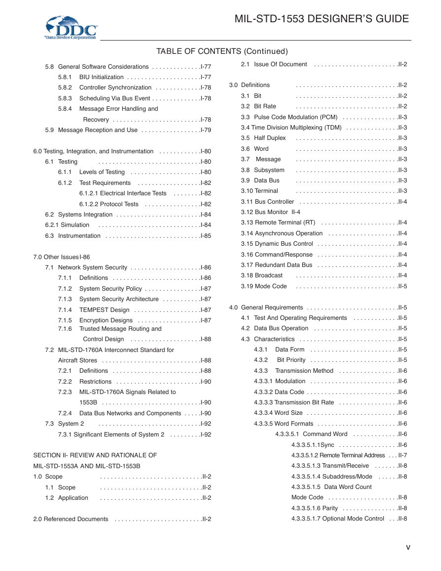
TABLE OF CONTENTS (Continued)
5.8 General Software Considerations . . . . . . . . . . . . . .I-77
5.8.1 BIU Initialization . . . . . . . . . . . . . . . . . . . . .I-77
5.8.2 Controller Synchronization . . . . . . . . . . . . .I-78
5.8.3 Scheduling Via Bus Event . . . . . . . . . . . . . .I-78
5.8.4 Message Error Handling and
Recovery . . . . . . . . . . . . . . . . . . . . . . . . .I-78
5.9 Message Reception and Use . . . . . . . . . . . . . . . . .I-79
6.1 Testing
6.1.1
6.1.2 Test Requirements
6.0 Testing, Integration, and Instrumentation . . . . . . . . . . . .I-80
. . . . . . . . . . . . . . . . . . . . . . . . . . . . .I-80
Levels of Testing . . . . . . . . . . . . . . . . . . . .I-80
. . . . . . . . . . . . . . . . . .I-82
6.1.2.1 Electrical Interface Tests
. . . . . . . .I-82
6.1.2.2 Protocol Tests . . . . . . . . . . . . . . . .I-82
6.2 Systems Integration . . . . . . . . . . . . . . . . . . . . . . . .I-84
6.2.1 Simulation
. . . . . . . . . . . . . . . . . . . . . . . . . . . . .I-84
6.3 Instrumentation . . . . . . . . . . . . . . . . . . . . . . . . . . .I-85
7.0 Other IssuesI-86
7.1 Network System Security . . . . . . . . . . . . . . . . . . . .I-86
7.1.1 Definitions . . . . . . . . . . . . . . . . . . . . . . . . .I-86
7.1.2 System Security Policy . . . . . . . . . . . . . . . .I-87
7.1.3 System Security Architecture . . . . . . . . . . .I-87
7.1.4 TEMPEST Design . . . . . . . . . . . . . . . . . . .I-87
7.1.5 Encryption Designs . . . . . . . . . . . . . . . . . .I-87
7.1.6 Trusted Message Routing and
Control Design . . . . . . . . . . . . . . . . . . . .I-88
7.2 MIL-STD-1760A Interconnect Standard for
Aircraft Stores . . . . . . . . . . . . . . . . . . . . . . . . . . . .I-88
7.2.1 Definitions . . . . . . . . . . . . . . . . . . . . . . . . .I-88
7.2.2 Restrictions . . . . . . . . . . . . . . . . . . . . . . . .I-90
7.2.3 MIL-STD-1760A Signals Related to
1553B . . . . . . . . . . . . . . . . . . . . . . . . . . . .I-90
7.2.4 Data Bus Networks and Components . . . . .I-90
. . . . . . . . . . . . . . . . . . . . . . . . . . . . .I-92
7.3.1 Significant Elements of System 2 . . . . . . . . .I-92
7.3 System 2
SECTION II- REVIEW AND RATIONALE OF
MIL-STD-1553A AND MIL-STD-1553B
1.0 Scope
1.1 Scope
1.2 Application
. . . . . . . . . . . . . . . . . . . . . . . . . . . . .II-2
. . . . . . . . . . . . . . . . . . . . . . . . . . . . .II-2
. . . . . . . . . . . . . . . . . . . . . . . . . . . . .II-2
2.0 Referenced Documents . . . . . . . . . . . . . . . . . . . . . . . . .II-2
2.1 Issue Of Document
. . . . . . . . . . . . . . . . . . . . . . . .II-2
3.0 Definitions
. . . . . . . . . . . . . . . . . . . . . . . . . . . . .II-2
. . . . . . . . . . . . . . . . . . . . . . . . . . . . .II-2
3.1 Bit
3.2 Bit Rate
. . . . . . . . . . . . . . . . . . . . . . . . . . . . .II-2
3.3 Pulse Code Modulation (PCM) . . . . . . . . . . . . . . . .II-3
3.4 Time Division Multiplexing (TDM) . . . . . . . . . . . . . . .II-3
. . . . . . . . . . . . . . . . . . . . . . . . . . . . .II-3
3.5 Half Duplex
. . . . . . . . . . . . . . . . . . . . . . . . . . . . .II-3
3.6 Word
. . . . . . . . . . . . . . . . . . . . . . . . . . . . .II-3
3.7 Message
3.8 Subsystem
. . . . . . . . . . . . . . . . . . . . . . . . . . . . .II-3
. . . . . . . . . . . . . . . . . . . . . . . . . . . . .II-3
3.9 Data Bus
3.10 Terminal
. . . . . . . . . . . . . . . . . . . . . . . . . . . . .II-3
3.11 Bus Controller . . . . . . . . . . . . . . . . . . . . . . . . . . . .II-4
3.12 Bus Monitor II-4
3.13 Remote Terminal (RT) . . . . . . . . . . . . . . . . . . . . . .II-4
3.14 Asynchronous Operation . . . . . . . . . . . . . . . . . . . .II-4
3.15 Dynamic Bus Control . . . . . . . . . . . . . . . . . . . . . . .II-4
3.16 Command/Response . . . . . . . . . . . . . . . . . . . . . . .II-4
3.17 Redundant Data Bus . . . . . . . . . . . . . . . . . . . . . . .II-4
3.18 Broadcast
. . . . . . . . . . . . . . . . . . . . . . . . . . . . .II-4
. . . . . . . . . . . . . . . . . . . . . . . . . . . . .II-5
3.19 Mode Code
4.0 General Requirements . . . . . . . . . . . . . . . . . . . . . . . . . .II-5
4.1 Test And Operating Requirements . . . . . . . . . . . . .II-5
4.2 Data Bus Operation . . . . . . . . . . . . . . . . . . . . . . . .II-5
4.3 Characteristics . . . . . . . . . . . . . . . . . . . . . . . . . . . .II-5
4.3.1 Data Form . . . . . . . . . . . . . . . . . . . . . . . . .II-5
4.3.2
Bit Priority . . . . . . . . . . . . . . . . . . . . . . . . .II-5
4.3.3 Transmission Method . . . . . . . . . . . . . . . . .II-6
4.3.3.1 Modulation . . . . . . . . . . . . . . . . . . . . . . . . .II-6
4.3.3.2 Data Code . . . . . . . . . . . . . . . . . . . . . . . . . .II-6
4.3.3.3 Transmission Bit Rate . . . . . . . . . . . . . . . . .II-6
4.3.3.4 Word Size . . . . . . . . . . . . . . . . . . . . . . . . . .II-6
4.3.3.5 Word Formats . . . . . . . . . . . . . . . . . . . . . . .II-6
4.3.3.5.1 Command Word . . . . . . . . . . . . .II-6
4.3.3.5.1.1Sync . . . . . . . . . . . . . . . . .II-6
4.3.3.5.1.2 Remote Terminal Address . . . II-7
4.3.3.5.1.3 Transmit/Receive . . . . . . .II-8
4.3.3.5.1.4 Subaddress/Mode . . . . . .II-8
4.3.3.5.1.5 Data Word Count
Mode Code . . . . . . . . . . . . . . . . . . . .II-8
4.3.3.5.1.6 Parity . . . . . . . . . . . . . . . .II-8
4.3.3.5.1.7 Optional Mode Control . . .II-8
v
�
MIL-STD-1553 DESIGNER’S GUIDE
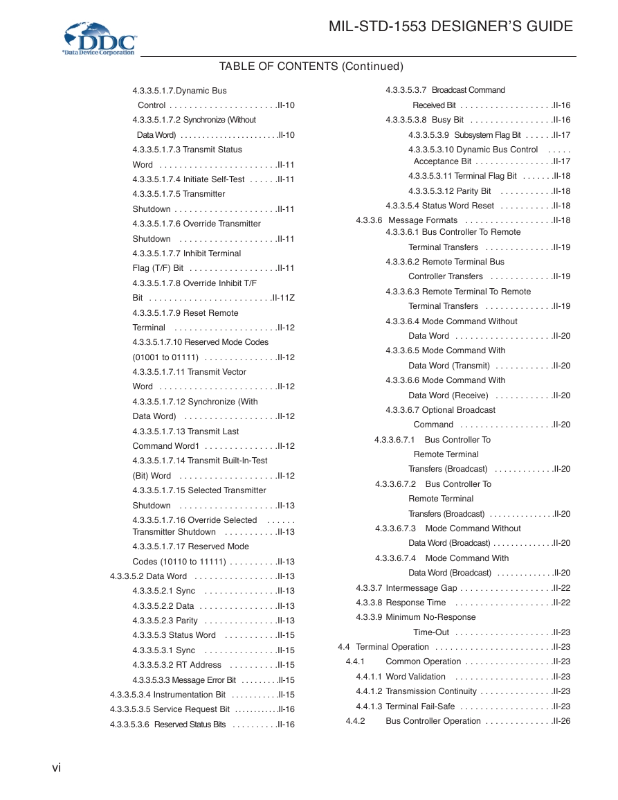
TABLE OF CONTENTS (Continued)
4.3.3.5.1.7.Dynamic Bus
4.3.3.5.3.7 Broadcast Command
Control . . . . . . . . . . . . . . . . . . . . . .II-10
4.3.3.5.1.7.2 Synchronize (Without
Data Word) . . . . . . . . . . . . . . . . . . . . . . .II-10
4.3.3.5.1.7.3 Transmit Status
Word . . . . . . . . . . . . . . . . . . . . . . . .II-11
4.3.3.5.1.7.4 Initiate Self-Test . . . . . .II-11
4.3.3.5.1.7.5 Transmitter
Shutdown . . . . . . . . . . . . . . . . . . . . .II-11
4.3.3.5.1.7.6 Override Transmitter
Shutdown . . . . . . . . . . . . . . . . . . . .II-11
4.3.3.5.1.7.7 Inhibit Terminal
Flag (T/F) Bit . . . . . . . . . . . . . . . . . .II-11
4.3.3.5.1.7.8 Override Inhibit T/F
Bit . . . . . . . . . . . . . . . . . . . . . . . . .II-11Z
4.3.3.5.1.7.9 Reset Remote
Terminal . . . . . . . . . . . . . . . . . . . . .II-12
4.3.3.5.1.7.10 Reserved Mode Codes
(01001 to 01111) . . . . . . . . . . . . . . .II-12
4.3.3.5.1.7.11 Transmit Vector
Word . . . . . . . . . . . . . . . . . . . . . . . .II-12
4.3.3.5.1.7.12 Synchronize (With
Data Word) . . . . . . . . . . . . . . . . . . .II-12
4.3.3.5.1.7.13 Transmit Last
Command Word1 . . . . . . . . . . . . . . .II-12
4.3.3.5.1.7.14 Transmit Built-ln-Test
(Bit) Word . . . . . . . . . . . . . . . . . . . .II-12
4.3.3.5.1.7.15 Selected Transmitter
Shutdown . . . . . . . . . . . . . . . . . . . .II-13
4.3.3.5.1.7.16 Override Selected
. . . . . .
Transmitter Shutdown . . . . . . . . . . .II-13
4.3.3.5.1.7.17 Reserved Mode
Codes (10110 to 11111) . . . . . . . . . .II-13
4.3.3.5.2 Data Word . . . . . . . . . . . . . . . . .II-13
4.3.3.5.2.1 Sync . . . . . . . . . . . . . . .II-13
4.3.3.5.2.2 Data . . . . . . . . . . . . . . . .II-13
4.3.3.5.2.3 Parity . . . . . . . . . . . . . . .II-13
4.3.3.5.3 Status Word . . . . . . . . . . .II-15
4.3.3.5.3.1 Sync . . . . . . . . . . . . . . .II-15
4.3.3.5.3.2 RT Address . . . . . . . . . .II-15
4.3.3.5.3.3 Message Error Bit . . . . . . . . .II-15
4.3.3.5.3.4 Instrumentation Bit . . . . . . . . . . .II-15
4.3.3.5.3.5 Service Request Bit . . . . . . . . . . . .II-16
4.3.3.5.3.6 Reserved Status Bits . . . . . . . . . .II-16
vi
Received Bit . . . . . . . . . . . . . . . . . . .II-16
4.3.3.5.3.8 Busy Bit . . . . . . . . . . . . . . . . .II-16
4.3.3.5.3.9 Subsystem Flag Bit . . . . . .II-17
. . . . .
4.3.3.5.3.10 Dynamic Bus Control
Acceptance Bit . . . . . . . . . . . . . . . .II-17
4.3.3.5.3.11 Terminal Flag Bit . . . . . . .II-18
4.3.3.5.3.12 Parity Bit . . . . . . . . . . .II-18
4.3.3.5.4 Status Word Reset . . . . . . . . . . .II-18
4.3.3.6 Message Formats . . . . . . . . . . . . . . . . . .II-18
4.3.3.6.1 Bus Controller To Remote
Terminal Transfers . . . . . . . . . . . . . .II-19
4.3.3.6.2 Remote Terminal Bus
Controller Transfers . . . . . . . . . . . . .II-19
4.3.3.6.3 Remote Terminal To Remote
Terminal Transfers . . . . . . . . . . . . . .II-19
4.3.3.6.4 Mode Command Without
Data Word . . . . . . . . . . . . . . . . . . . .II-20
4.3.3.6.5 Mode Command With
Data Word (Transmit) . . . . . . . . . . . .II-20
4.3.3.6.6 Mode Command With
Data Word (Receive) . . . . . . . . . . . .II-20
4.3.3.6.7 Optional Broadcast
Command . . . . . . . . . . . . . . . . . . .II-20
4.3.3.6.7.1 Bus Controller To
Remote Terminal
Transfers (Broadcast) . . . . . . . . . . . . .II-20
4.3.3.6.7.2 Bus Controller To
Remote Terminal
Transfers (Broadcast) . . . . . . . . . . . . . . .II-20
4.3.3.6.7.3 Mode Command Without
Data Word (Broadcast) . . . . . . . . . . . . . .II-20
4.3.3.6.7.4 Mode Command With
Data Word (Broadcast) . . . . . . . . . . . . .II-20
4.3.3.7 Intermessage Gap . . . . . . . . . . . . . . . . . . .II-22
4.3.3.8 Response Time . . . . . . . . . . . . . . . . . . . .II-22
4.3.3.9 Minimum No-Response
4.4.1
Time-Out . . . . . . . . . . . . . . . . . . . .II-23
4.4 Terminal Operation . . . . . . . . . . . . . . . . . . . . . . . .II-23
Common Operation . . . . . . . . . . . . . . . . . .II-23
4.4.1.1 Word Validation
. . . . . . . . . . . . . . . . . . . .II-23
4.4.1.2 Transmission Continuity . . . . . . . . . . . . . . .II-23
4.4.1.3 Terminal Fail-Safe . . . . . . . . . . . . . . . . . . .II-23
Bus Controller Operation . . . . . . . . . . . . . .II-26
4.4.2
�
MIL-STD-1553 DESIGNER’S GUIDE
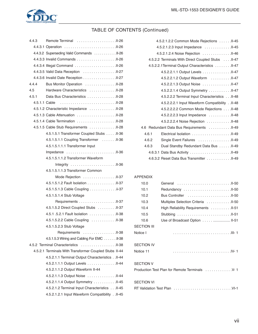
TABLE OF CONTENTS (Continued)
4.4.3
4.4.4
4.5
4.5.1
Remote Terminal . . . . . . . . . . . . . . . . . . .II-26
4.4.3.1 Operation . . . . . . . . . . . . . . . . . . . . . . . . .II-26
4.4.3.2 Superseding Valid Commands . . . . . . . . . . . .II-26
4.4.3.3 Invalid Commands . . . . . . . . . . . . . . . . . . .II-26
4.4.3.4 Illegal Command . . . . . . . . . . . . . . . . . . . .II-26
4.4.3.5 Valid Data Reception . . . . . . . . . . . . . . . .II-27
4.4.3.6 Invalid Date Reception . . . . . . . . . . . . . . . .II-27
Bus Monitor Operation . . . . . . . . . . . . . . .II-28
Hardware Characteristics . . . . . . . . . . . . .II-28
Data Bus Characteristics . . . . . . . . . . . . . .II-28
4.5.1.1 Cable . . . . . . . . . . . . . . . . . . . . . . . . . . .II-28
4.5.1.2 Characteristic Impedance . . . . . . . . . . . . .II-28
4.5.1.3 Cable Attenuation . . . . . . . . . . . . . . . . . . .II-28
4.5.1.4 Cable Termination . . . . . . . . . . . . . . . . . . .II-28
4.5.1.5 Cable Stub Requirements . . . . . . . . . . . . .II-28
4.5.1.5.1 Transformer Coupled Stubs . . . . .II-36
4.5.1.5.1.1 Coupling Transformer . . . . . . .II-36
4.5.1.5.1.1.1 Transformer Input
Impedance . . . . . . . . . . . . . . . . . . . . . . . .II-36
4.5.1.5.1.1.2 Transformer Waveform
Integrity . . . . . . . . . . . . . . . . . . . . . .II-36
4.5.1.5.1.1.3 Transformer Common
Mode Rejection . . . . . . . . . . . . . . . .II-37
4.5.1.5.1.2 Fault Isolation . . . . . . . . . . . . . .II-37
4.5.1.5.1.3 Cable Coupling . . . . . . . . . . . . .ii-37
4.5.1.5.1.4 Stub Voltage
Requirements . . . . . . . . . . . . . . . . . .II-37
4.5.1.5.2 Direct Coupled Stubs . . . . . . . . .II-37
4.5.1 .5.2.1 Fault Isolation . . . . . . . . . . . . .II-38
4.5.1.5.2.2 Cable Coupling . . . . . . . . . . . .II-38
4.5.1.5.2.3 Stub Voltage
Requirements . . . . . . . . . . . . . . . .II-38
4.5.1.5.3 Wiring and Cabling For EMC . . . . . . .II-38
4.5.2 Terminal Characteristics . . . . . . . . . . . . . . . . .II-38
4.5.2.1 Terminals With Transformer Coupled Stubs II-44
4.5.2.1.1 Terminal Output Characteristics . .II-44
4.5.2.1.1.1 Output Levels . . . . . . . . . . . . . .II-44
4.5.2.1.1.2 Output Waveform II-44
4.5.2.1.1.3 Output Noise . . . . . . . . . . . . . .II-44
4.5.2.1.1.4 Output Symmetry . . . . . . . . . . .II-45
4.5.2.1.2 Terminal Input Characteristics . . .II-45
4.5.2.1.2.1 Input Waveform Compatibility . .II-45
4.5.2.1.2.2 Common Mode Rejections . . . . . .II-45
4.5.2.1.2.3 Input Impedance . . . . . . . . . . . . .II-45
4.5.2.1.2.4 Noise Rejection . . . . . . . . . . . . . .II-46
4.5.2.2 Terminals With Direct Coupled Stubs . . . .II-47
4.5.2.2.1Terminal Output Characteristics . . . . . . . .II-47
4.5.2.2.1.1 Output Levels . . . . . . . . . . . . . .II-47
4.5.2.2.1.2 Output Waveform
. . . . . . . . . .II-47
4.5.2.2.1.3 Output Noise . . . . . . . . . . . . . .II-47
4.5.2.2.1.4 Output Symmetry . . . . . . . . . . .II-47
4.5.2.2.2 Terminal Input Characteristics . . .II-48
4.5.2.2.2.1 Input Waveform Compatibility . .II-48
4.5.2.2.2.2 Common Mode Rejections . . . .II-48
4.5.2.2.2.3 Input Impedance . . . . . . . . . . .II-48
4.5.2.2.2.4 Noise Rejection . . . . . . . . . . . .II-48
4.6 Redundant Data Bus Requirements . . . . . . . . . . .II-49
Electrical Isolation . . . . . . . . . . . . . . . . . . .II-49
Single Event Failures . . . . . . . . . . . . . . . .II-49
Dual Standby Redundant Data Bus . . . . . .II-49
4.6.3.1 Data Bus Activity . . . . . . . . . . . . . . . . . . . .II-49
4.6.3.2 Reset Data Bus Transmitter . . . . . . . . . . . .II-49
4.6.1
4.6.2
4.6.3
APPENDIX
10.0
10.1
10.2
10.3
10.4
10.5
10.6
SECTION III
Notice I
SECTION IV
Notice 11
General . . . . . . . . . . . . . . . . . . . . . . . . . .II-50
Redundancy . . . . . . . . . . . . . . . . . . . . . . .II-50
Bus Controller . . . . . . . . . . . . . . . . . . . . .II-50
Multiplex Selection Criteria . . . . . . . . . . . .II-50
High Reliability Requirements . . . . . . . . . .II-51
Stubbing . . . . . . . . . . . . . . . . . . . . . . . . . .II-51
Use of Broadcast Option . . . . . ................. II-51
. . . . . . . . . . . . . . . . . . . . . . . . . . . .III- 1
. . . . . . . . . . . . . . . . . . . . . . . . . . . .IV- 1
SECTION V
Production Test Plan for Remote Terminals . . . . . . . . . . . . .V- 1
SECTION VI
RT Validation Test Plan . . . . . . . . . . . . . . . . . . . . . . . . . . . .VI-1
vii
�
MIL-STD-1553 DESIGNER’S GUIDE
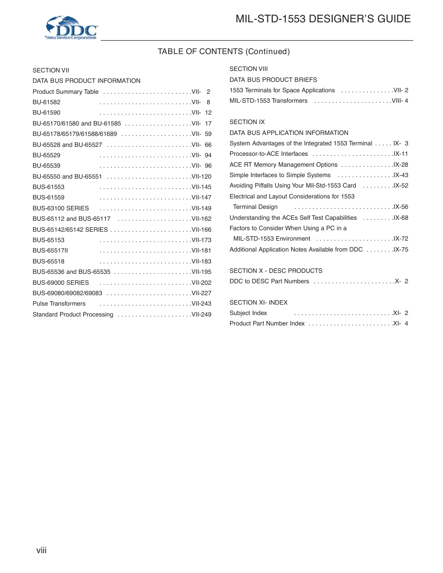
TABLE OF CONTENTS (Continued)
SECTION VII
DATA BUS PRODUCT INFORMATION
Product Summary Table . . . . . . . . . . . . . . . . . . . . . . . . .VII- 2
. . . . . . . . . . . . . . . . . . . . . . . . . .VII- 8
BU-61582
BU-61590
. . . . . . . . . . . . . . . . . . . . . . . . . .VII- 12
BU-65170/61580 and BU-61585 . . . . . . . . . . . . . . . . . . .VII- 17
BU-65178/65179/61588/61689 . . . . . . . . . . . . . . . . . . . .VII- 59
BU-65528 and BU-65527 . . . . . . . . . . . . . . . . . . . . . . . .VII- 66
. . . . . . . . . . . . . . . . . . . . . . . . . .VII- 94
BU-65529
BU-65539
. . . . . . . . . . . . . . . . . . . . . . . . . .VII- 96
BU-65550 and BU-65551 . . . . . . . . . . . . . . . . . . . . . . . .VII-120
. . . . . . . . . . . . . . . . . . . . . . . . . .VII-145
BUS-61553
BUS-61559
. . . . . . . . . . . . . . . . . . . . . . . . . .VII-147
. . . . . . . . . . . . . . . . . . . . . . . . . .VII-149
BUS-63100 SERIES
BUS-65112 and BUS-65117
. . . . . . . . . . . . . . . . . . . . .VII-162
BUS-65142/65142 SERIES . . . . . . . . . . . . . . . . . . . . . . .VII-166
BUS-65153
. . . . . . . . . . . . . . . . . . . . . . . . . .VII-173
. . . . . . . . . . . . . . . . . . . . . . . . . .VII-181
BUS-65517II
BUS-65518
. . . . . . . . . . . . . . . . . . . . . . . . . .VII-183
BUS-65536 and BUS-65535 . . . . . . . . . . . . . . . . . . . . . .VII-195
BUS-69000 SERIES
. . . . . . . . . . . . . . . . . . . . . . . . . .VII-202
BUS-69080/69082/69083 . . . . . . . . . . . . . . . . . . . . . . . .VII-227
Pulse Transformers
. . . . . . . . . . . . . . . . . . . . . . . . . .VII-243
Standard Product Processing . . . . . . . . . . . . . . . . . . . . .VII-249
SECTION VIII
DATA BUS PRODUCT BRIEFS
1553 Terminals for Space Applications . . . . . . . . . . . . . . .VII- 2
MIL-STD-1553 Transformers . . . . . . . . . . . . . . . . . . . . . .VIII- 4
SECTION IX
DATA BUS APPLICATION INFORMATION
System Advantages of the Integrated 1553 Terminal . . . . . IX- 3
Processor-to-ACE Interfaces . . . . . . . . . . . . . . . . . . . . . . .IX-11
ACE RT Memory Management Options . . . . . . . . . . . . . . .IX-28
Simple Interfaces to Simple Systems
. . . . . . . . . . . . . . . .IX-43
Avoiding Piffalls Using Your Mil-Std-1553 Card . . . . . . . . .IX-52
Electrical and Layout Considerations for 1553
Terminal Design
. . . . . . . . . . . . . . . . . . . . . . . . . . . .IX-56
Understanding the ACEs Self Test Capabilities . . . . . . . . .IX-68
Factors to Consider When Using a PC in a
MIL-STD-1553 Environment . . . . . . . . . . . . . . . . . . . . . .IX-72
Additional Application Notes Available from DDC . . . . . . . .IX-75
SECTION X - DESC PRODUCTS
DDC to DESC Part Numbers . . . . . . . . . . . . . . . . . . . . . . .X- 2
SECTION XI- INDEX
Subject Index
. . . . . . . . . . . . . . . . . . . . . . . . . . . .XI- 2
Product Part Number Index . . . . . . . . . . . . . . . . . . . . . . . .XI- 4
viii
�


 2023年江西萍乡中考道德与法治真题及答案.doc
 2012年重庆南川中考生物真题及答案.doc
 2013年江西师范大学地理学综合及文艺理论基础考研真题.doc
 2020年四川甘孜小升初语文真题及答案I卷.doc
 2020年注册岩土工程师专业基础考试真题及答案.doc
 2023-2024学年福建省厦门市九年级上学期数学月考试题及答案.doc
 2021-2022学年辽宁省沈阳市大东区九年级上学期语文期末试题及答案.doc
 2022-2023学年北京东城区初三第一学期物理期末试卷及答案.doc
 2018上半年江西教师资格初中地理学科知识与教学能力真题及答案.doc
 2012年河北国家公务员申论考试真题及答案-省级.doc
 2020-2021学年江苏省扬州市江都区邵樊片九年级上学期数学第一次质量检测试题及答案.doc
 2022下半年黑龙江教师资格证中学综合素质真题及答案.doc