EnI l口.附阳川O佣侃…R盹L
[;Ill_~ 1 ~ 1 #1 #1 :)1 Hfiì
STANDARDS
General Specification
GMW14241
GMLAN Device Test Specification for GMLAN High-Speed,
Mid-Speed, Low-Speed CAN Bus Nodes
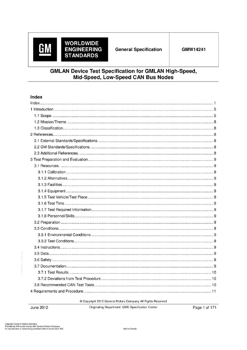
Index
Index............................................................................................................................................................... 1
1 Introduction................………… ........... .... .……........………………........…………·…..............................................5
1.1 Scope. …………………………………..........................…….............................……….........………....................5
1.2 Mission/Theme ........ ... ... .... ............... ... .................. .... ... ... ..... ...... .... ... ............... ... .... ............... ... ... .........8
1.3 Classification. .…………….......….............................................................................................................8
2 References.……… .......………… ........... .... .……........……………….......………………............. .…….........................8
2.1 External Standards/Specifications. ……........…………………........………………….........……..........................8
2.2 GM Standards/Specifications. ……………….......…………..................………………........…............................8
2.3 Additional References. . .....……........................……………………………………………………........………..........8
3 Test Preparation and Evaluation. ………....................................................................................................9
3.1 Resources. ….... ....…………. ... ...... ...... .... ...….........…….......……………………... .......... .……·…………….........9
3. 1. 1 Calibration ..... .... ... ....... ....... ..……………........………………................………………·………........…...........9
3.1.2 Alternatives........ ……….........…..................………………·………........…….........……… ...........................9
3.1.3 Facilities ............................................……….........……………………………………........……....................9
3.1 .4 Equipment..... .... ... .... ... ....... .... ......……………………………….......………………… ...............9
3.1.5 Test Vehicle/Test Piece ........................ ......................... ..................... ............................................. 9
3. 1.6 Test Time ............. ..............…………... ....………….. ......…..................…………………·……........…...........9
3.1.7 Test Required Information.. ………………………………………..................................................9
3. 1.8 Personnel/Skills .... ....………........……………………..........…·……........……………………........…….............9
3.2 Preparation............ …….......…………………….......…………………… ........................................9
3.3 Conditions.…........……………………........ .….........………… .........…..…….........…………………….........…........9
3.3.1 Environmental Conditions ... ..........…………….......…….................…………...............…·…....................9
3.3.2 Test Conditions.…………….........................………............................……….........................................9
3.4 Instructions ........…………………………….........…·…………………….........…..................................................9
3.5 Data..…….........…·……...............……................……...........................….............….........…….........…........9
3.6 Safety .... ....……............... .... .....……………........……………………..…........……………… ..... .............……........9
3.7 Documentation. …… ..............................................................................................................................9
3.7.1 Test Results ................................…………………….......………………………………·……………………......10
3.7.2 Deviations from Test Procedure .………………………………………………………….... ....….. ...... .…...........10
3.8 Recommended CAN Test Tools. ................................... ....................…….......……...........................10
4 Requirements and Procedure... .......………….....…….........…………….......…………........................….........….. 11
June 2012
。 Copyright 2012 General Motors Company AII Rights Reserved
Originating Department: GME Specification Center
Page 1 of 171
C叩yrighl General Motors C阴阳ny
Provided by IHS unð刷刷cense w协GeneraJ Motors Com.阳呵
No reproduCOOn ()(附加。tkj吨 perm闹剧刷刷。回除捕、se ft,臼n l HS
阳阳 R酷a始
�
| GM WORLDWIDE ENGINEERING STANDARDS
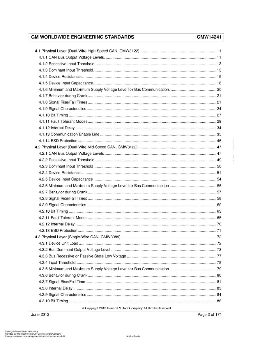
4.1 Physical Layer (Dual-Wire High-Speed CAN , GMW3122).................…………………………………... ... ....... 11
4.1.1 CAN Bus Output Voltage Levels. ..................................................... ......................... ... ..................1 1
4. 1.2 Recessive Input Threshold........................…………………………………………………............................13
4. 1.3 Dominant Input Threshold. ........ .........………………………………………·……………. .... ...... ..... .…...........13
4.1 .4 Device Resistance. …………… …………………… ......................................................................15
4.1.5 Device Input Capacitance. .................…..............………................………..............................………..18
4.1.6 Minimum and Maximum Supply Voltage Level for Bus Communication. …..... ............………............20
4.1.7 Behavior duri ng Crank................................................................................................................... 21
4.1.8 Signal Rise/FaJl Ti mes. .... .................…….........…..................……..........…........……........................21
4.1 .9 Signal Characteristics ............. ..................... .............................…........….......….............................24
4.1.10 Bit Ti ming ....................................................................................................................................27
4.1.11 Fault Tolerant Modes...................................................................................................................29
4. 1.1 2 InternaJ Delay ..... ......………………………………….........……….........…….........…………………… ..........34
4.1.13 Communication Enable Line ........................................................................................................35
4.1.14 ESD Protection ...... .... .......……………………........…·…….........…………...............…….......................46
4.2 Physical Layer (Dual-Wire Mid-Speed CAN, GMW3122) ...................................................................... 47
4.2.1 CAN Bus Output Voltage Levels ....................................................................................................47
4.2.2 Recessive Input Threshold.................……………………………………......……………·…........……...........49
4.2.3 Dominant Input Threshold..............................................................................................................50
4.2.4 Device Resistance. ... ... ....... ..…………….........…·……….... ....………………………………........................51
4.2.5 Device Input Capacitance ... ...... ....…..………........………................………........... .... ..... ....…..............54
4.2.6 Minimum and Maximum Supply Voltage Level fo r Bus Communication ..........................................56
4.2.7 Behavior during Crank. ..............…….........……………………….........………·………………………….........57
4.2.8 Signal Rise/Fall Ti mes ...................................................................................................................58
4.2.9 Signal Characteristics ...... ......... ....……….............……………........……………·….................................60
4.2.10 Bit Ti ming …………………………………........………............................................................................63
4.2.11 Fault Tolerant Modes...................................................................................................................65
4.2.12 InternaJ Delay ..............................................................................................................................70
4.2.13 ESD Protection ...........................…………….......……….........……...............…·….............................71
4.3 Physical Layer (Single-Wire CAN, GMW3089) ....... ..................... .....…........…......................................72
4.3.1 Device Unit Load .. .... ... .... ........... ... ...........…………………................……….........……..……................72
4.3.2 Bus Dominant Output Voltage Level ... ...... ....... ... ............... ... ...... ................………..........................73
4.3.3 Bus Recessive or Passive State Low Voltage ..................................….........................................77
4.3.4 Input Threshold.. ... ... ...……................…….........…..................……….........……·……..........................78
4.3.5 Minimum and Maximum Supply Voltage Level for Bus Communication ........…...............................79
4.3.6 Behavior during Crank. ..................... ....………….............................................................................80
4.3.7 Signal Rise/Fall Ti me.....................................................................................................................81
4.3.8 Internal Delay ... .... ....……………………………………........…….........………..........…………………….........83
4.3.9 Signal Characteristics ...... .................….........…........……........................……..................................84
4.3.10 Bit Ti ming ....................................................................................................................................86
June 2012
Page 2 of 171
。 Copyright 2012 General Motors Company AII Rights Reserved
C叩yrighl General Motors C阴阳ny
Provided by IHS u nð刷刷cense w协GeneraJ Motors Com.阳呵
No reproduCOOn ()(附加。tkj吨 perm闹剧刷刷。回 除捕、se ft,臼n l HS
阳阳 R酷a始
�
I GM WORLDWIDE ENGINEERING STANDARDS
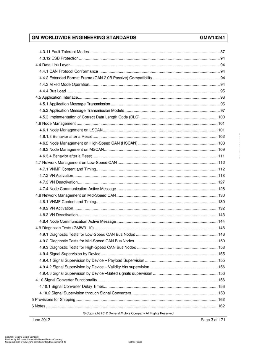
4.3.11 Fault Tolerant Modes..……………………………………..............…………………....................................87
4.3.12 ESD Protection ... ... .... ............... ... ... ........ ....... .... ...... .... ........ ... ... ....... ....... ........ ............... ...... .... ...94
4.4 Data Link Layer.…........….......…................…........……..……………………...........................………............94
4.4.1 CAN Protocol Conformance.………….......……………………………………………………………..................94
4.4.2 Extended Format Frame (CAN 2.0B Passive) Compatibility .. ....... ........................................... .......94
4.4.3 Mixed Mode Operation. .......……………………........…………….......………............................................94
4.4.4 Bus Load ....... .... ... ... ....... .... .... .....……………………................………………........…..…………………......95
4.5 Application Interlace........................................................................ ..................................................... 96
4.5.1 Application Message Transmission . .......….........….........….........…….....................……...................96
4.5.2 Application Message Transmission Models.... …….. .....………. ........…………………………...................97
4.5.3 Implementation of Correct Data Length Code (DLC) ...... .... ... ....... ........... .... ..................... ............ 100
4.6 Node Management .. .......... ............... ....... ... .... ........... ... ....... .............. ....... ............... ............... ...... ..... 101
4.6.1 Node Management on LSCAN.. ….........……………………………………….........…………………............101
4.6.1.3 Behavior after a Reset ......... .... ... ... ........ ....... .... ... ... .... ....... .... .... ... ....... .... .... ... ... .... .... .... ... ... ..... 102
4.6.2 Node Management on High-Speed CAN (HSCAN) ......................................................................103
4.6.3 Node Management on MSCAN....…………. ... ..…….. .....………. ...... ...…………………………........……..109
4.6.3.4 Behavior after a Reset ....................... ....................................... .... .................. ... .......................111
4.7 Network Management on Low-Speed CAN ..............................................................….........…………..112
4.7.1 VNMF Content and Timing………………………… ....................................................................112
4.7.2 VN Activation. …………………………………... .....…………….. ................……·…….......… .... ....…….........113
4.7.3 VN Deactivation. …….......……..............................…………….......………........……..…........….........… 127
4.7.4 Node Communication Active Message.........................................................................................128
4.8 Network Management on Mid-Speed CAN .. .... ... ...……………........……….........……………………………… 130
4.8.1 VNMF Content and Timing………………………… ....................................................................130
4.8.2 VN Activation... ....………......……………………........…………….......…………·….........…….......………….132
4.8.3 VN Deactivation. ………………………………………………….......…………………..........…........................143
4.8.4 Node Communication Active Message.........................................................................................144
4.9 Diagnostic Tests (GMW311 0) ....................................... ....................…........……… ......................146
4.9.1 Diagnostic Tests for Low-Speed CAN Bus Nodes ...........……........….........………..........................146
4.9.2 Diagnostic Tests for Mid-Speed CAN Bus Nodes ........ ....... ..............………………….........….......….150
4.9.3 Diagnostic Tests for High-Speed CAN Bus Nodes ............. .....................................………………… 153
4.9.4 Signal Supervision by Device.………….......……………………………….......…….........…….......….........155
4.9.4.1 Signal Supervision by Device - Payload Supervision ...... ..........................................................155
4.9.4.2 Signal Supervision by Device - Validity bits supervision.. ... ....................…….............................156
4.9.4.3 Signal Supervision by Device -Gated signals supervision .. ....... ..............……….................……..156
4.10 Signal Converter Functionality..…….......…………………….........………………….........…..........…............156
4.10.1 Signal Converter Delay Ti mes....................................................................................................156
4.10.2 Signal Supervision through Signal Converters.…………….......…………………………………..............158
5 Provisions for Shipping... ... ....... .................………….......………….........………............................….........…… 162
6 Notes .......................................................................................................................................................162
June 2012
Page 3 of 171
。 Copyright 2012 General Motors Company AII Rights Reserved
C叩yrighl General Motors C阴阳ny
Provided by IHS unð刷 刷cense w协GeneraJ Motors Com.阳呵
No reproduCOOn ()(附加。tkj吨 perm闹剧刷刷。回 除捕、seft,臼n l HS
阳阳 R酷a始
�
I GM WORLDWIDE ENGINEERING STANDARDS
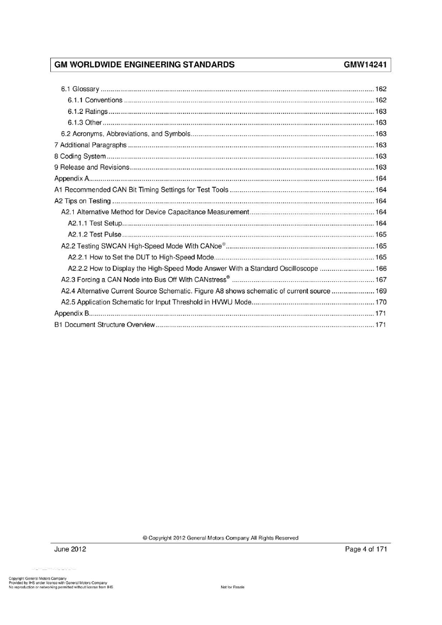
6.1 Glossary . ... .......... .... ... ... .... ....... .... ... .... ... ............... ... ....... .... ....…....... .......… .............…......................162
6.1.1 Conventions .. .... ... ... .... ........... .... ... ............... ... .... .......... ....... .... ... ....... ..... ... ....... ............... ...... ..... 162
6.1.2 Ratings .......................................... ..................... ........……….........…….........................................163
6.1.3 Other .. .... ....... .... ...... ........ ... .... .... ... ... .... .... ... .....……………........…………….........………….........…….163
6.2 Acronyms, Abbreviations, and Symbols. ... ... .... ... ........ .... ...... .... ........…........……·…… ...................163
7 Additional Paragraphs ......………......….............................…........…........…………….........…………...............163
8 Coding System .......................………………..................………·………………………………………………..............163
9 Release and Revisions..............…………................................................................................................163
Appendix A. ....…. ... ... ....... ....……......................….........…….. ...... .….........…….............................…........ .…… 164
A1 Recommended CAN Bit Ti ming Settings for Test Tools ....................... .......................... .......……............1 64
A2 Tips on Testing ...................................................................................................................................... 164
A2.1 Alternative Method for Device Capacitance Measurement.…… .......................................................164
A2.1.1 Test Setup. …….......…………........………………….........……….........…….........….............................164
A2.1.2 Test Pulse ................................... ... .................. ....... .................................................................. 165
A2.2 Testing SWCAN High-Speed Mode With CANoe@......…..................................…......…….........…......165
A2.2.1 How to Set the DUT to High-Speed Mode. ……………………… ...........................................165
A2.2.2 How to Di制 ay the High-Speed Mode Answer With a Standard Oscilloscope ..... ....... .... ........ .... 166
A2.3 Forcing a CAN Node into Bus αf With CANstress@ .... .... ....... .... ... ... .... ... .... .... ... .... .......... ..... ... ... ..... 167
A2.4 Alternative Current Source Schematic. Figure A8 shows schematic of current source ... ............... .... 169
A2.5 Application Schematic for Input Threshold in HVWU Mode..…………….........……................…….........170
Appendix B.............................................................................................……………………………………...........171
B1 Document Structure Overview........…….........……………….........…………………………….............................171
June 2012
Page 4 of 171
。 Copyright 2012 General Motors Company AII Rights Reserved
C叩yrighl General Motors C阴阳ny
Provided by IHS u nð刷刷cense w协GeneraJ Motors Com.阳呵
No teproduCOOn ()(附加。tkj吨 perm闹剧刷刷。回 除捕、se ft,臼n l HS
阳阳 R酷a始
�
I GM WORLDWIDE ENGINEERING STANDARDS
1 Introduction
Note: Nothing in this standard supersedes applicable laws and regulations.
Note: In the event of conflict between the English and domestic language, the English language sha川 take
precedence.
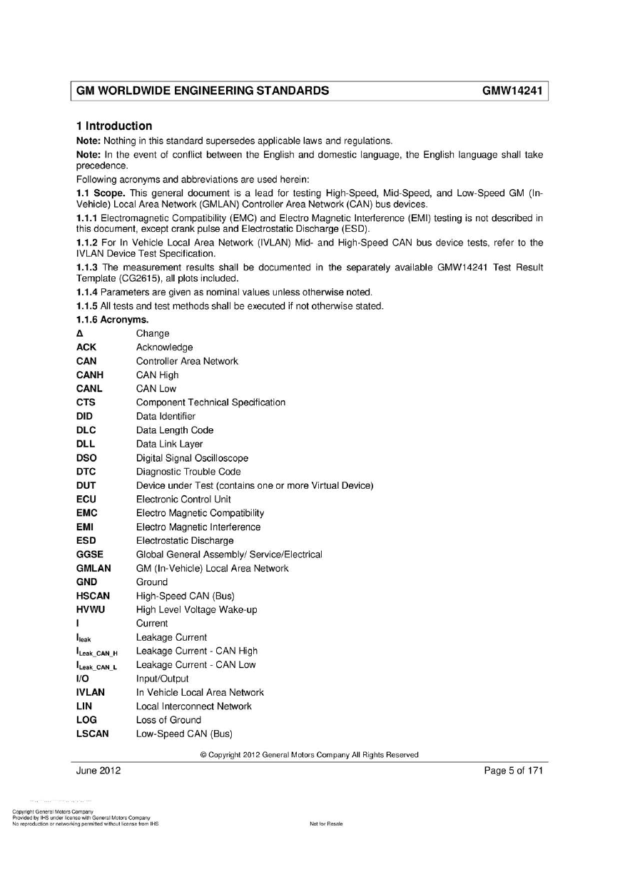
Following acronyms and abbreviations are used herein:
1.1 Scope. This general document is a lead for testing High-Speed, Mid-Speed, and Low-Speed GM (In
Vehicle) Local Area Network (GMLAN) Controller Area Network (CAN) bus devices.
1.1 . 1 日ectromagnetic Compatibility (EMC) and Electro Magnetic Inte斤erence (EMI) testing is not described in
this document, except crank pulse and Electrostatic Discharge (ESD).
1.1.2 For In Vehicle Local Area Network (IVLAN) Mid- and High-Speed CAN bus device tests, refer to the
IVLAN Device Test Specification.
1.1.3 The measurement results shall be documented in the separately available GMW14241 Test Result
Template (CG261 日 , all plots included.
1.1.4 Parameters are given as nominal values unless otherwise noted.
1.1.5 AII tests and test methods shall be executed if not otherwise stated
1.1.6 Acronyms.
11
ACK
CAN
AATmLLSTU
n
N
U
N
F
S
UV
l
户
u
C
v
L
n
u
O
n
C
u
T
n
u
U
n
C
u
l
n
u
D
n
S
u
L
E
C
D
C
MMSGMNSV
HLEAAU
』
Change
Acknowledge
Controller Area Network
CAN High
CAN Low
Component Technical Specification
Data Identifier
Data Length Code
Data Link Layer
Digital Signal Oscilloscope
Diagnostic Trouble Code
Device under Test (contains one or more Virtual Device)
Electronic Control Unit
Electro Magnetic Compatibility
Electro Magnetic Inte付erence
Electrostatic Discharge
Global General Assembly/ Service/Electrical
GM (In-Vehicle) Local Area Network
Ground
High-Speed CAN (Bus)
High Level Voltage Wake-up
Current
Leakage Current
Leakage Current - CAN High
Leakage Current - CAN Low
Input/Output
In Vehicle Local Area Network
Loca川 nterconnect Network
Loss of Ground
Low-Speed CAN (Bus)
E
』
E
』
NN
内
E
』
n
M
户u
n
M
U
H
M
H
E
·
Ileak
ILeak CAN H
ILeak CAN L
1/0
IVLAN
LlN
LOG
LSCAN
June 2012
Page 5 of 171
。 Copyright 2012 General Motors Company AII Rights Reserved
C叩yrighl General Motors C阴阳ny
Provided by IHS unð刷刷cense w协GeneraJ Motors Com.阳呵
No teproduCOOn ()(附加。tkj吨 perm闹剧刷刷。回 除捕、seft,臼nlHS
阳阳 R酷a始
�
| GM WORLDWIDE ENGINEERING STANDARDS
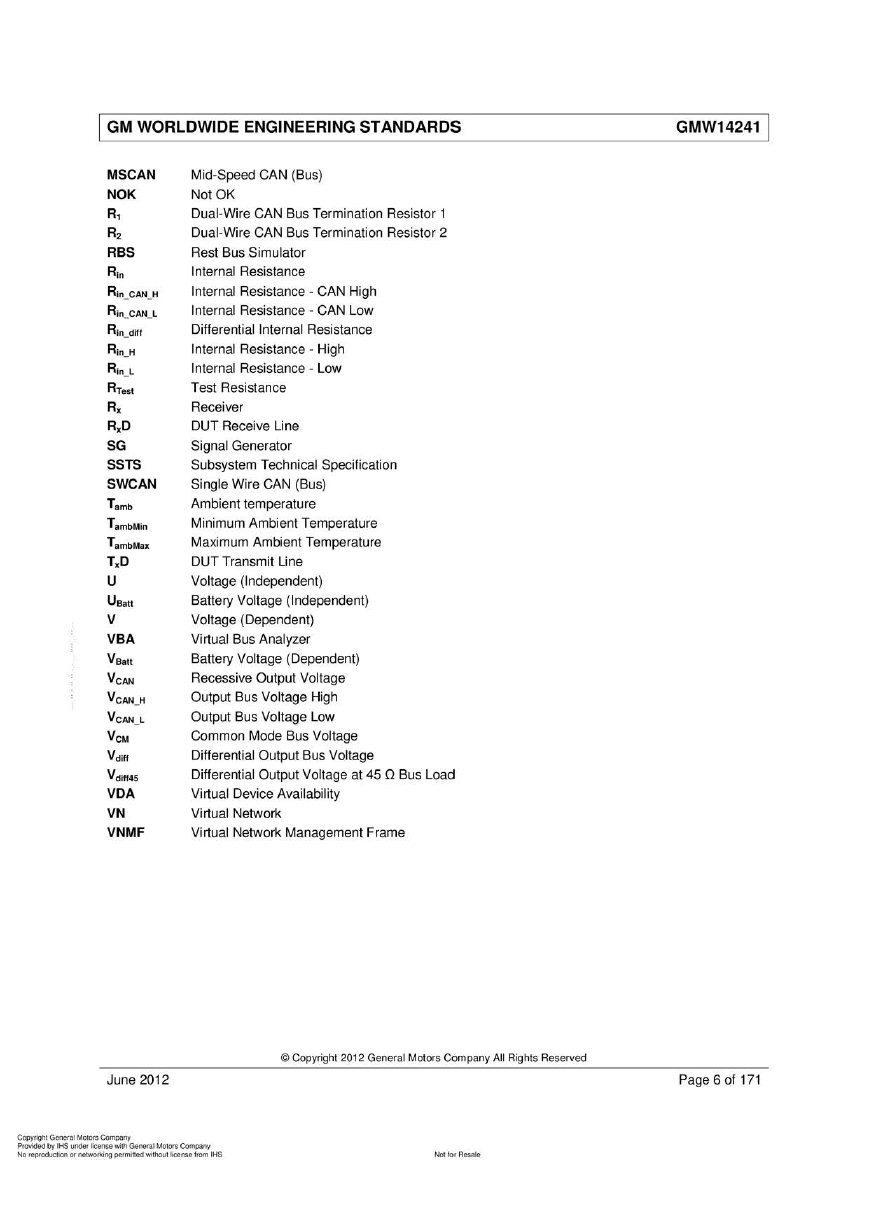
MSCAN
NOK
R1
R2
RBS
Rin
Rin CAN H
Rin CAN L
Rin diff
Rin H
Rin L
RTest
Rx
RxD
SG
SSTS
SWCAN
Tamb
TambMin
TambMax
TxD
U
UBatt
v
VBA
VBatt
VCAN
VCAN H
VCAN L
VCM
VdiH
VdlH45
VDA
VN
VNMF
Mid-Speed CAN (Bus)
NotOK
Dual-Wire CAN Bus Termination Resistor 1
Dual-Wire CAN Bus Termination Resistor 2
Rest Bus Simulator
Internal Resistance
Internal Resistance - CAN High
Internal Resistance - CAN Low
Differential Internal Resistance
Internal Resistance - High
Internal Resistance - Low
Test Resistance
Receiver
DUT Receive Line
Signal Generator
Subsystem Technical Specification
Single Wire CAN (Bus)
Ambient temperature
Minimum Ambient Temperature
Maximum Ambient Temperature
DUT Transmit Une
Voltage (Independent)
Ba口ery Voltage (Independent)
Voltage (Dependent)
Virtual Bus Analyzer
Battery Voltage (Dependent)
Recessive Output Voltage
Output Bus Voltage High
Output Bus Voltage Low
Common Mode Bus Voltage
Differential Output Bus Voltage
Differential Output Voltage at 45 n Bus Load
Virtual Device Availability
Virtual Network
Virtual Network Management Frame
June 2012
Page 6 of 171
。 Copyright 2012 General Motors Company AII Rights Reserved
C叩yrighl General Motors C阴阳ny
Provided by IHS unð刷刷cense w协GeneraJ Motors Com.阳呵
No teproduCOOn ()(附加。tkj吨 perm闹剧刷刷。回 除捕、seft,臼nlHS
阳阳 R酷a始
�
| GM WORLDWIDE ENGINEERING STANDARDS
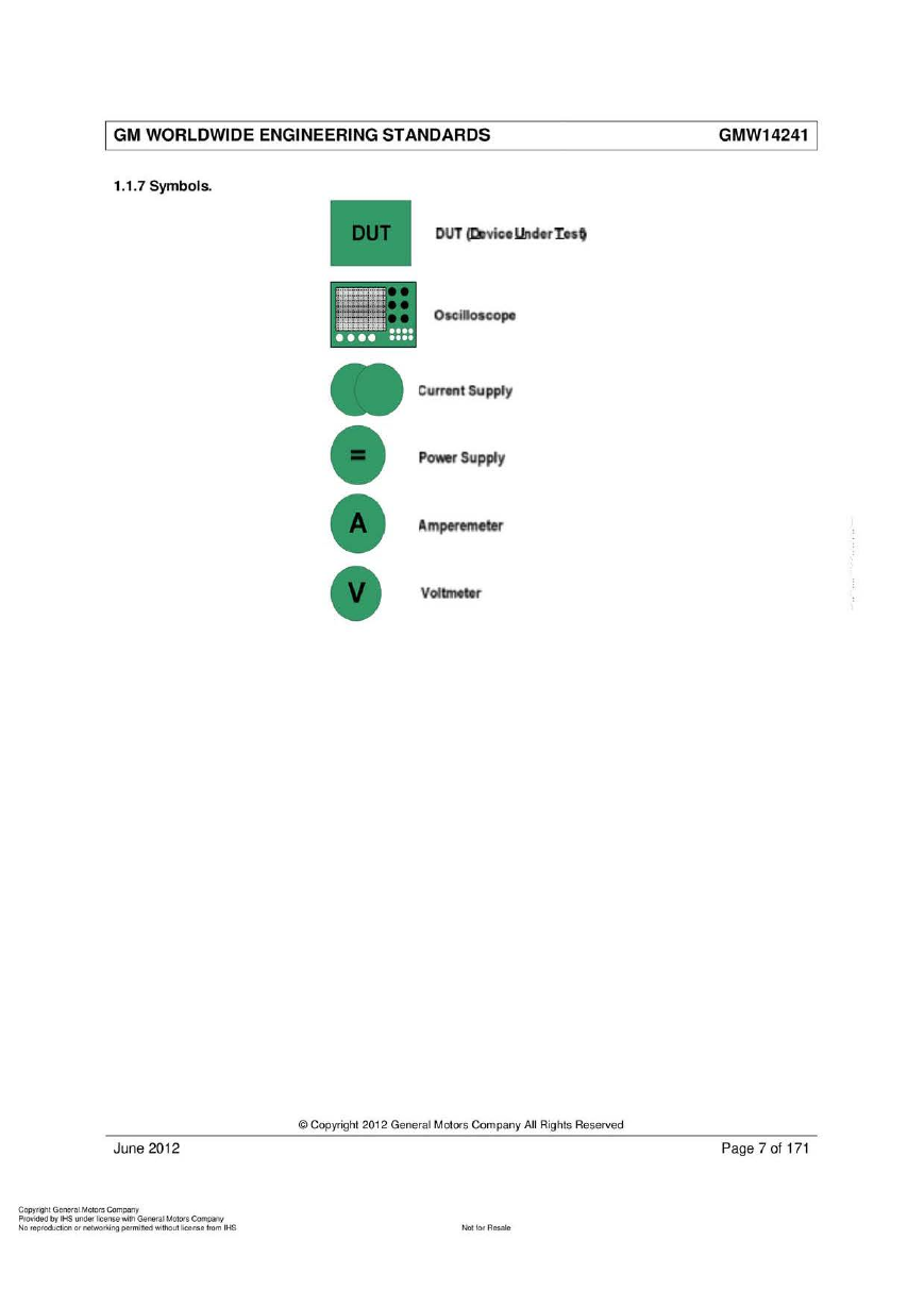
1.1 .7 Symbols.
DUT ~'Vtç. ur咐.r:[.事'
。K i005C:Ope
Cun;伤, t Supply
P制wer Suppfy
Amptlme始r
VoIcm.t.r
June 2012
Page 7 of 171
。 Copyright 2012 General Motors Company AII Rights Reserved
C即yrighl General Moto陌Com阳呵
p'o价由dby lHS un曲f Ilcense wÎlh GeneraJ M。阳帽Company
NO l即'oduα阳、。fnetwo,刷吨 ρefmitt回峭thoU\ Itceflse fr,阳n l HS
"。‘ lo
I GM WORLDWIDE ENGINEERING STANDARDS
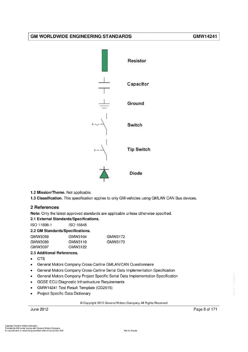
Resistor
Capacit or
Ground
Switch
Tip Switch
Diode
L
T
l十
-
A
)
气
|
本
1.2 Mission厅heme. Not applicable.
1.3 Classification. This specification applies to only GM vehicles using GMLAN CAN Bus devices.
ISO 16845
GMW3172
GMW3173
GMW3104
GMW3110
GMW312.2
2 References
Note: Only the latest approved standards are applicable unless otherwise specified.
2.1 External Standards/Specifications.
ISO 11898-1
2.2 GM Standards/Specifications.
GMW3059
GMW3089
GMW3097
2.3 Additional References.
• CTS
• General Motors Company Cross-Carline GMLAN/CAN Questionnaire
• General Motors Company Cross-Carline SeriaJ Data Implementation Specification
• General Motors Company Project Specific Serial Data Implementation Specification
• GGSE ECU Diagnostic Infrastructure Requirements
• GMW14241 Test Result Template (CG2615)
•
Pr叫 ect Specific Data Dictionary
June 2012
Page 8 of 171
。 Copyright 2012 General Motors Company AII Rights Reserved
C即yrighl General Moto陌Com阳呵
p'o价由dby lHS un曲f Ilcense wÎlh GeneraJ M。阳帽Company
NO l即'oduα阳、 。fnetwo,刷吨 ρefmitt回峭thoU\ Itceflse fr,阳n l HS
"。‘ lo


 2023年江西萍乡中考道德与法治真题及答案.doc
 2012年重庆南川中考生物真题及答案.doc
 2013年江西师范大学地理学综合及文艺理论基础考研真题.doc
 2020年四川甘孜小升初语文真题及答案I卷.doc
 2020年注册岩土工程师专业基础考试真题及答案.doc
 2023-2024学年福建省厦门市九年级上学期数学月考试题及答案.doc
 2021-2022学年辽宁省沈阳市大东区九年级上学期语文期末试题及答案.doc
 2022-2023学年北京东城区初三第一学期物理期末试卷及答案.doc
 2018上半年江西教师资格初中地理学科知识与教学能力真题及答案.doc
 2012年河北国家公务员申论考试真题及答案-省级.doc
 2020-2021学年江苏省扬州市江都区邵樊片九年级上学期数学第一次质量检测试题及答案.doc
 2022下半年黑龙江教师资格证中学综合素质真题及答案.doc