USER’S GUIDE
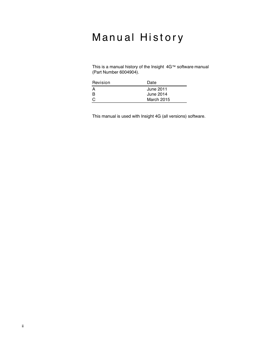
Manual History
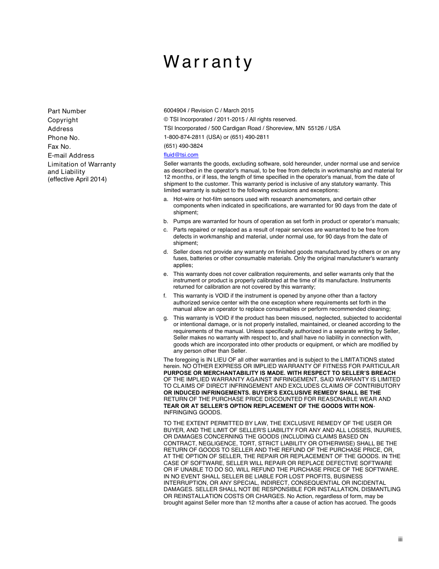
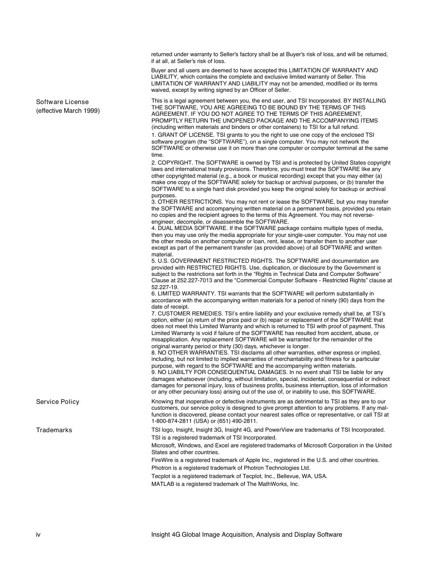
Warranty
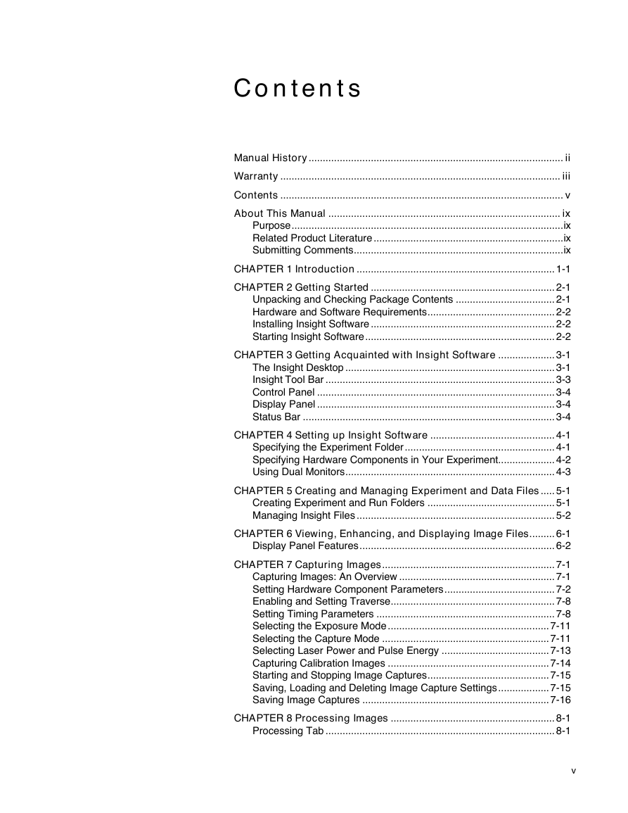
Contents
About This Manual
Purpose
Related Product Literature
Submitting Comments
CHAPTER 1 Introduction
CHAPTER 2 Getting Started
Unpacking and Checking Package Contents
Hardware and Software Requirements
Installing Insight Software
Starting Insight Software
CHAPTER 3 Getting Acquainted with Insight Software
The Insight Desktop
Insight Menu Options
Experiment/Run
Tools
Window
Help
Insight Tool Bar
Control Panel
Display Panel
Status Bar
CHAPTER 4 Setting up Insight Software
Specifying the Experiment Folder
To Specify an Experiment Folder
Specifying Hardware Components in Your Experiment
To Specify the Hardware Components in your Experiment
Using Dual Monitors
To Use Two Monitors
CHAPTER 5 Creating and Managing Experiment and Data Files
Creating Experiment and Run Folders
Creating an Experiment
Creating a Run
Editing an Experiment or Run
Managing Insight Files
Accessing the Experiment Tree
Specifying the Sorting Order for Data Files
To Specify the Display Order of Data Files
Setting an Experiment or Run as Current
To Specify an Experiment or Run as Current
Renaming an Experiment/Run Folder
Deleting an Experiment/Run Folder
Expanding or Collapsing the Experiment Tree
To Expand an Experiment Folder
To Collapse an Experiment Tree
CHAPTER 6 Viewing, Enhancing, and Displaying Image Files
Display Panel Features
Zooming In and Out of Image Files
To Resize, Zoom In or Out of Image Files
Display While Processing – “Turbo Mode”
Create Image List
Applying Crosshairs
To Turn on Crosshairs
To Turn off Crosshairs
Applying Grids
To Turn on Grid Option
To Turn off Grid Option
Selecting Entire Images
To Select the Entire Image
Enhancing Image Displays by Modifying Look Up Tables (LUT)
To Use the LUT Option
Editing, Displaying, and Clearing Vectors
To Setup Vectors
Getting Information on Images
Image Statistics
To Display Image Statistics
To Export Image Statistics
To Print Image Statistics
To Send the Image Statistics Table to a Clipboard
Image Histogram
To Display the Image Histogram
Image Information
To Display the Image Information
Vector Information
To Display the Vector Statistics
To Display the Vector Histogram
Line Profile
Exporting Images
To Export Images
Animating Images
To Animate Images
CHAPTER 7 Capturing Images
Capturing Images: An Overview
Set Parameters to Capture Images
Capture Images
Capture Images Post-Trigger
Save Capture Settings and Images to Disk
Setting Hardware Component Parameters
Setting Synchronizer Parameters
Setting Laser Parameters
Laser Setup Parameters
Setting Camera Parameters
Camera Setup Parameters
Enabling and Setting Traverse
Setting Timing Parameters
To Setup Timing for Image Captures
Timing Setup Parameters
Viewing and Adjusting Timing Parameters
Selecting the Exposure Mode
Selecting the Capture Mode
Selecting Laser Power and Pulse Energy
To Check or Set the Q-Switch Delay for Each Power Level
To Select Laser Power Level
To Turn the Laser On or Off
Capturing Calibration Images
Starting and Stopping Image Captures
To Start Capturing Images
To Stop Capturing Images
Saving, Loading and Deleting Image Capture Settings
To Save Capture Settings
To Load Capture Settings
To Delete Previously-loaded Capture Settings
Saving Image Captures
To Save Captured Images to the Hard Drive
CHAPTER 8 Processing Images
Processing Tab
Select Application
Select Spatial Calibration
Select Region of Interest
Select Processing Mask
Select Image Preprocessing
Select Processing and Data Post-Processing
View Processing Progress
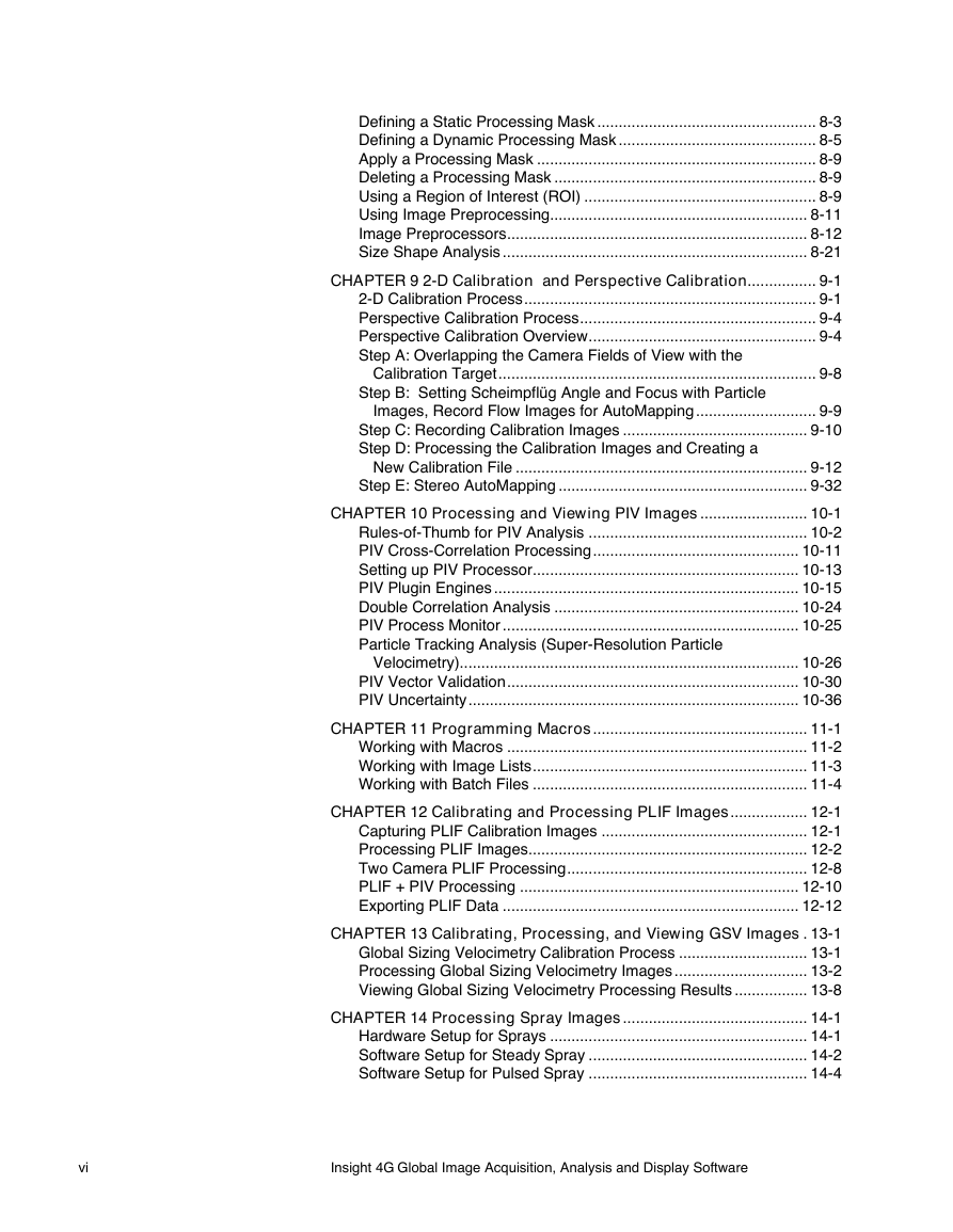
Defining a Static Processing Mask
Defining a Dynamic Processing Mask
Creating Dynamic Masks
Altering an Individual Mask
Apply a Processing Mask
Deleting a Processing Mask
Using a Region of Interest (ROI)
Using Image Preprocessing
To set up Preprocessing Pipeline
To Apply a Preprocessing Pipeline
Image Preprocessors
Image Calculator
Select an Operation
Reverse Order
Image Binning
Image Filter
Image Generator
Image Dewarping
Image Deformation
Image Shift
Image Interpolation
Background Image Subtraction
To configure a Background Image Subtraction Preprocessor
Background Image Subtraction using Two Preprocessors
Size Shape Analysis
Setting up Size Shape Analysis Processor
Setting up SSA Sizing Processor
CHAPTER 9 2-D Calibration and Perspective Calibration
2-D Calibration Process
To Perform 2-D Calibration
Perspective Calibration Process
Perspective Calibration Overview
Calibration Targets
Stereo PIV Camera Location
Step A: Overlapping the Camera Fields of View with the Calibration Target
To Align the Cameras
Step B: Setting Scheimpflüg Angle and Focus with Particle Images, Record Flow Images for AutoMapping
Step C: Recording Calibration Images
Single-Plane Target Mounted on a Traverse
Two-Plane or Four-Plane Target
Step D: Processing the Calibration Images and Creating a New Calibration File
Calibration Processing: Overview
To Create a New Perspective Calibration:
Analyzing Calibration Images
Setting the Threshold Value
Defining the Target
To Define the Single-Plane Fiducial Marker Grid Values
To Define the Two-Plane Fiducial Marker Grid Values
To Define the Four-Plane Fiducial Marker Grid Values
Analyze Options Dialog
To Specify the Region of Interest and Object Size
Tools and Troubleshooting
Choosing Positive or Negative Settings
To Toggle Between Negative and Positive Settings
Choosing Blue/Red | Gray and Color Schemes
To Select a Color Scheme
Using the Histogram to Set Threshold Level
To Display the Histogram
To Change the Y Log Scale Factor in the Histogram
Verifying Calibration Markers in the Calibration Points and Calibrations Files
To Verify Markers
To Fix Improperly Identified Markers
Creating a Calibration File from the CPT Files
To Create a Calibration File
Viewing a Calibration File
Step E: Stereo AutoMapping
What is Stereo Automapping?
To Verify and Optimize Calibration Target Location
Calibration for Measurements through a Window
CHAPTER 10 Processing and Viewing PIV Images
Rules-of-Thumb for PIV Analysis
Rule 1: Interrogation-Spot Size should be Small Enough for One Vector to Describe Flow for that Spot
Rule Breaker
Rule 2: Should Have More than Ten Particle Image Pairs Per Interrogation Spot
Rule Breaker
Rule 3: Maximum In-Plane Displacements should be Less than One-Fourth Interrogation Spot Size
Rule Breaker
Rule 4: Maximum Out-of-Plane Displacement should be Less than One-Fourth of Light Sheet Thickness
Rule Breaker
Rule 5: Minimum In-Plane Displacement should be Two Particle Image Diameters
Rule Breaker
Rule 6: Exposure should be Large Enough to Show Particles
Rule Breaker
PIV Cross-Correlation Processing
Setting up PIV Processor
PIV Plugin Engines
Grid Engines
Spot Mask Engines
Correlation Engines
Peak Engines
Edit Plugin Parameter and Plugin Data
Grid Engine Parameters
Spot Mask Engine Parameters
Correlation Engine Parameters
Peak Engine Parameters
Double Correlation Analysis
Double Correlation
PIV Process Monitor
Particle Tracking Analysis (Super-Resolution Particle Velocimetry)
Image Preprocessing
Setting up a Processor
Particle Identification
Local Flow Estimation
Particle Tracking
Velocity Interpolation
PIV Vector Validation
Setting up Vector Validation
Vector Local Validation
Vector Global Validation
Vector Conditioning
Filling Holes
Smoothing
PIV Uncertainty
Method
Component-wise Uncertainties
Exporting Uncertainties in Insight Software
CHAPTER 11 Programming Macros
Working with Macros
To Create a Macro
Working with Image Lists
Working with Batch Files
To Create a Batch File
To Run a Batch File
Other Tasks
CHAPTER 12 Calibrating and Processing PLIF Images
Capturing PLIF Calibration Images
Processing PLIF Images
Setting up PLIF Processor
PLIF Processing Method
Ratiometic Method
Linear Fit Method
PLIF MATLAB® Plugin
To Set up PLIF MATLAB® Plugin
To use PLIF MATLAB® Plugin
Two Camera PLIF Processing
PLIF + PIV Processing
Exporting PLIF Data
To Setup Scalar Data Export
CHAPTER 13 Calibrating, Processing, and Viewing GSV Images
Global Sizing Velocimetry Calibration Process
GSV Calibration
Processing Global Sizing Velocimetry Images
Processing GSV Image
Setting up GSV Sizing Processor
Setting GSV Tracking Processor
GSV Process Monitor
Viewing Global Sizing Velocimetry Processing Results
Opening GSV Data File as a Table
Viewing GSV Data File on Top of the Raw Image
Changing Display Settings for Particles
CHAPTER 14 Processing Spray Images
Hardware Setup for Sprays
Software Setup for Steady Spray
Software Setup for Pulsed Spray
Data Analysis
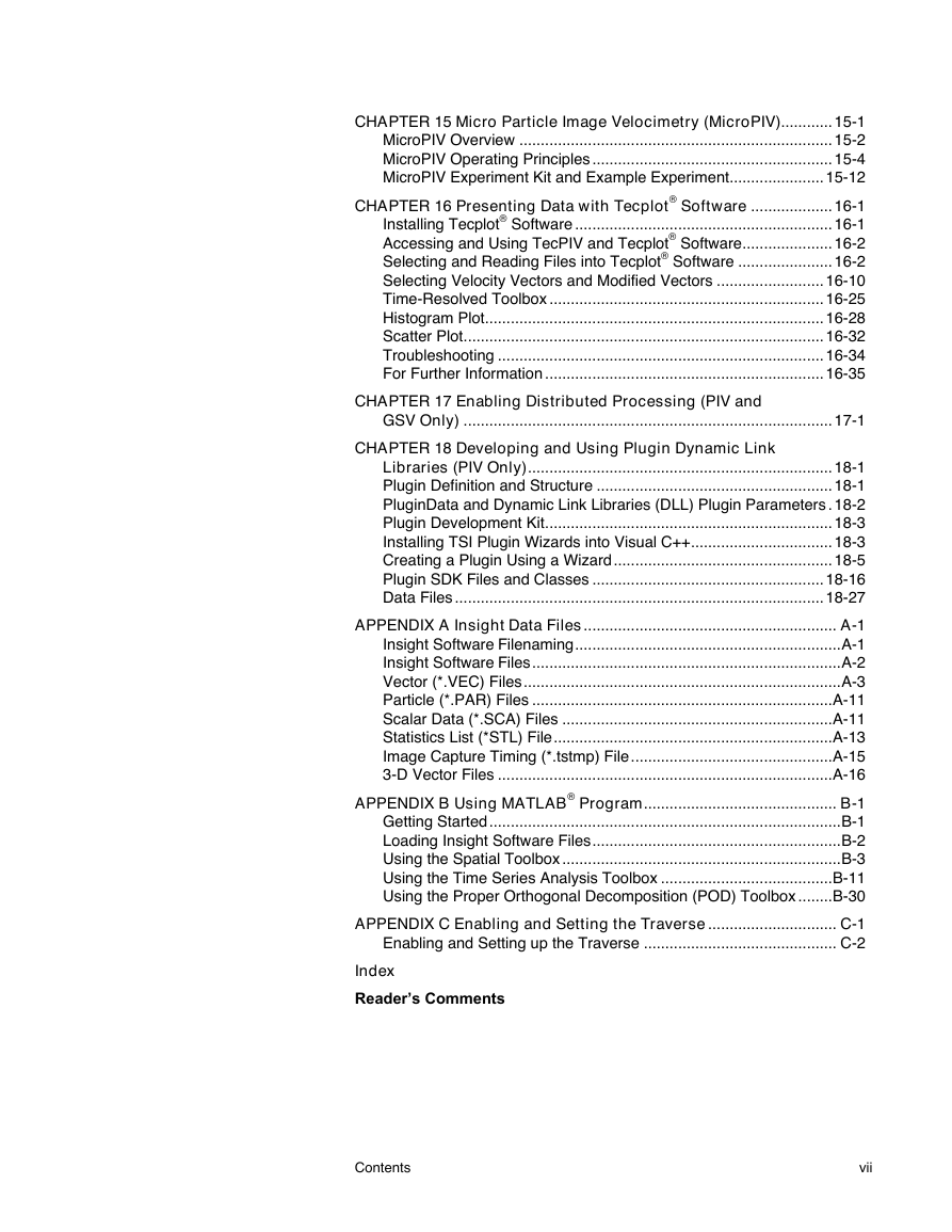
CHAPTER 15 Micro Particle Image Velocimetry (MicroPIV)
MicroPIV Overview
Microscopy Web Sites
MicroPIV Operating Principles
Fluorescent Particles
Filter Cube
White Light Illumination
Magnification and Field of View
MicroPIV Experiment Kit and Example Experiment
The MicroPIV Experiment
MicroPIV Experiment Setup
Ensemble Correlation Processing
Recursive Ensemble
Background Images
Maximum Intensity Image
Minimum and Average Intensity Image
CHAPTER 16 Presenting Data with Tecplot® Software
Installing Tecplot® Software
Accessing and Using TecPIV and Tecplot® Software
Selecting and Reading Files into Tecplot® Software
To Select and Open Vector Files
To Select More Than One File
Auto Binary Conversion
Selecting the Plot Types
Examples of Different Plots
Changing the Shape and Size of Arrows
To Change the Length of the Arrows
Selecting Velocity Vectors and Modified Vectors
Setting and Changing Contour Properties and Color
Selecting Contour Property
To Select a Contour Property
Table of Flow Properties for Vector Fields
Table of Flow Properties for Scalar Fields
Selecting Contour Type
To Select a Contour Type
Table of Contour Types
Selecting Vector Fields Arrow Colors
To Select Arrow Colors
Selecting Number of Colors
To Select Number of Colors
Selecting Contour Color Range
To Select the Contour Color Range
Selecting the Scalar Contour Minimum and Maximum
Selecting a Background
To toggle background color
Computing Average Fields and Other Quantities
Computing Average Fields
To Compute Average Fields
Computing Reynolds Stress/Density
To Compute Reynolds Stress/Density
Computing Turbulence Intensity
To Compute Turbulence Intensity
Subtracting Vector Files
Subtracting Reference Field
To Subtract Reference Field
Subtract Mean Velocity
Subtract Vec
Statistics Options
Velocity/Modified Velocity Check
CHC Statistics Button
CHC Choice Code Statistics Dialog
Stream Option
Number of Stream Traces
Clear
Rake Position
View Option
Changing the Shape and Size of Particles
To Change the Size of the Points
To Change the Shape of the Points
Viewing the Statistics of Particles
To View the Statistics of Particle Statistics
Message Option
Auto Open Vector Files Check Boxes
Edit Folders Dialog
Experiment Folder
Message Folder
Preplot Path Name
Save Button
Time-Resolved Toolbox
Time
Tracking
Histogram Plot
Y-Axis Parameter Selection
Bin Width and Number of Bins
Range
Cumulative
Sub-Integer Plot
Scatter Plot
Troubleshooting
For Further Information
CHAPTER 17 Enabling Distributed Processing (PIV and GSV Only)
To Setup your Computer for Distributed Processing
To Setup the Worker Computer for Distributed Processing
CHAPTER 18 Developing and Using Plugin Dynamic Link Libraries (PIV Only)
Plugin Definition and Structure
PluginData and Dynamic Link Libraries (DLL) Plugin Parameters
Plugin Parameters
Plugin Data
SNR Vector Validation
Plugin Development Kit
Installing TSI Plugin Wizards into Visual C++
Plugin Coordinates and Units
TSI Plugin Wizard Generated Code
ExampleCode
Creating a Plugin Using a Wizard
Customizing the Gaussian Spot Mask Engine
To Customize the Gaussian Spot Mask
Plugin SDK Files and Classes
BaseEngine Folder
BasePlugin
BaseGrid
BaseSpotMask
BaseCorrelator
BasePeak
Interface Classes
Data Files
APPENDIX A Insight Data Files
Insight Software Filenaming
Insight Software Files
Vector (*.VEC) Files
Choice (CHC) Codes
Error Vectors
Pixel *.VEC Files
Pixel *.VEC Header Line
Pixel *.VEC File Listing
Velocity *.VEC File
Velocity *.VEC Header Line
Velocity *.VEC File Listing
Average Vector (*AVG.VEC) File
Average Vector File Listing
Mean and Standard Deviation (*.STD) Vector File
Mean and Standard Deviation File Header
Mean and Standard Deviation File Listing
Particle (*.PAR) Files
Choice (CHC) Codes
Velocity Not Set
Scalar Data (*.SCA) Files
Single-Camera PLIF
Simultaneous PLIF-PIV
Multi-Camera PLIF
Statistics List (*STL) File
To Read the Statistics File into Microsoft® Excel® Spreadsheet Program
Statistics File Header
Statistics File Listing
Image Capture Timing (*.tstmp) File
Timing File Listing
3-D Vector Files
3-D Vector Header Line
3-D Vector (*.V3D) File Listing
APPENDIX B Using MATLAB® Program
Getting Started
Loading Insight Software Files
Using the Spatial Toolbox
Navigating the Spatial Toolbox
Spatial Toolbox Options
Arrow Options
Contour Quantity Modes
To Choose Contour Quantity Mode
Instantaneous Mode
Ensemble Averaged Mode
Fluctuations Mode
Turbulent Mode
Contour Types
Defining Contours
Animating Displays
To Start Animation
To Stop Animation
Creating Movies
To Create a Movie
Using the Time Series Analysis Toolbox
To Access the Time Toolbox
To Make a Selection
To Quit After Making a Selection
To Reset a Selection
Selecting Options for Analysis
Selecting Points
To Select Points
Selecting Regions
To Select Regions
Selecting Rows or Columns
To Select Rows or Columns
Selecting the Entire Map
To Select the Entire Map
Performing Profile Analysis
To Perform a Profile Analysis
Examples
Performing the Time Series Analysis
To Perform Time Series Analysis
Using the Proper Orthogonal Decomposition (POD) Toolbox
Select Options
Select/Add Region
Select All
Direct/Snapshot
Choosing Energy Content
Energy Content Controls
Navigation
Available Options
Arrow Options
Contour Quantity Modes
Output Options
Single POD Modes
Multi-Mode
Reconstruction of Fields
Contour Types
Control of Contour Levels and Colors
Animation and Movie Options
APPENDIX C Enabling and Setting the Traverse
Enabling and Setting up the Traverse
To Enable and Setup the Traverse
To Change to Manual Move Mode
To Change to Traverse Manager Control
To Set Up and Configure Axis
To Use the Traverse Manager
Index
Reader’s Comments


 2023年江西萍乡中考道德与法治真题及答案.doc
 2012年重庆南川中考生物真题及答案.doc
 2013年江西师范大学地理学综合及文艺理论基础考研真题.doc
 2020年四川甘孜小升初语文真题及答案I卷.doc
 2020年注册岩土工程师专业基础考试真题及答案.doc
 2023-2024学年福建省厦门市九年级上学期数学月考试题及答案.doc
 2021-2022学年辽宁省沈阳市大东区九年级上学期语文期末试题及答案.doc
 2022-2023学年北京东城区初三第一学期物理期末试卷及答案.doc
 2018上半年江西教师资格初中地理学科知识与教学能力真题及答案.doc
 2012年河北国家公务员申论考试真题及答案-省级.doc
 2020-2021学年江苏省扬州市江都区邵樊片九年级上学期数学第一次质量检测试题及答案.doc
 2022下半年黑龙江教师资格证中学综合素质真题及答案.doc