LTE Modelling in Atoll
version 2.8.3
�
�
Table of Contents
LTE Modelling in Atoll
Executive Summary............................................................................................................................... 4
LTE Network Planning Process in Atoll ............................................................................................... 5
3GPP LTE ............................................................................................................................................... 6
The 3GPP Standards Family ................................................................................................................ 7
OFDM, SOFDMA, and SC-FDMA: Concepts and System Parameters ................................................ 7
LTE Modelling in Atoll ......................................................................................................................... 11
Frequency Bands and Channel Bandwidths ....................................................................................... 12
LTE eNode-Bs .................................................................................................................................... 12
Adaptive Modulation and Coding ........................................................................................................ 14
Scheduling and Radio Resource Management ................................................................................... 14
Multiple Input Multiple Output Systems ............................................................................................... 15
Mobility Management .......................................................................................................................... 17
Atoll LTE Coverage Analysis Features .............................................................................................. 17
Coverage-based Analysis ................................................................................................................... 17
Interference-based Analysis ............................................................................................................... 19
Point Analysis Tool ............................................................................................................................. 20
Network Verification Using Measurement Data .................................................................................. 20
Multi-Layer 2G/3G/LTE Coverage Analysis ........................................................................................ 21
Atoll LTE Traffic Model and Capacity Analysis Features ................................................................. 21
Bearers ............................................................................................................................................... 22
Services .............................................................................................................................................. 23
User Equipment .................................................................................................................................. 23
User Profiles ....................................................................................................................................... 23
Traffic Data ......................................................................................................................................... 24
Raster, Vector, and Live Traffic Maps .............................................................................................. 24
Fixed Subscribers Database ............................................................................................................ 25
LTE Monte Carlo Simulations ............................................................................................................. 25
Atoll LTE Automatic Planning Features ............................................................................................ 27
Automatic Cell Planning ...................................................................................................................... 27
Full and Fractional Frequency Planning .............................................................................................. 28
Physical Cell ID Planning .................................................................................................................... 30
Neighbour Planning ............................................................................................................................ 30
2G/3G/LTE Inter-RAT Neighbour Planning ......................................................................................... 31
References ........................................................................................................................................... 31
Glossary of Terms ............................................................................................................................... 32
1
2
3
3.1
3.2
4
4.1
4.2
4.3
4.4
4.5
4.6
5
5.1
5.2
5.3
5.4
5.5
6
6.1
6.2
6.3
6.4
6.5
6.5.1
6.5.2
6.6
7
7.1
7.2
7.3
7.4
7.5
8
9
© Forsk 2010
3
�
LTE Modelling in Atoll
1
Executive Summary
LTE (Long Term Evolution) is the common name given to the 3GPP E-UTRA (Evolved UMTS
Terrestrial Radio Access) technology. LTE is the next generation of 3GPP 2G and 3G families of
cellular networks, i.e., GSM/GPRS/EGPRS and UMTS/HSPA. This white paper describes the 3GPP
LTE technology, how it is modelled in Atoll, and how LTE networks can be designed, analysed, and
optimised using Atoll.
This white paper starts with a short description of the LTE network planning process in Atoll. The LTE
technology is briefly described in the following section within the context of cellular network planning
and optimisation. The next section describes how LTE network entities, parameters, and features are
modelled in Atoll, and the subsequent sections describe the numerous features available in Atoll for
planning, studying, and analysing LTE networks.
LTE aims at providing improvements over existing 2G and 3G networks in terms of data rate (around
100 Mbps in downlink and 50 Mbps in uplink in the first phase), in terms of the variety of services that
can be provided over a single infrastructure (VoIP, streaming video, TV, VOD, etc.), and in terms of the
quality of the provided services (shorter connection delays, priority-based bandwidth sharing, etc.).
In addition to the above, LTE promises a smooth transition from existing 2G and 3G networks, the
intrinsic ability to support multiple-antenna diversity techniques (such as MIMO), and a platform open to
further evolution over the next decade.
As a part of the most successful family of cellular communications standards, and with its predecessors,
GSM and UMTS, accounting for almost 90% of the industry’s market share (number of mobile phone
subscriptions in the world), LTE is all set to become the leading 4G technology.
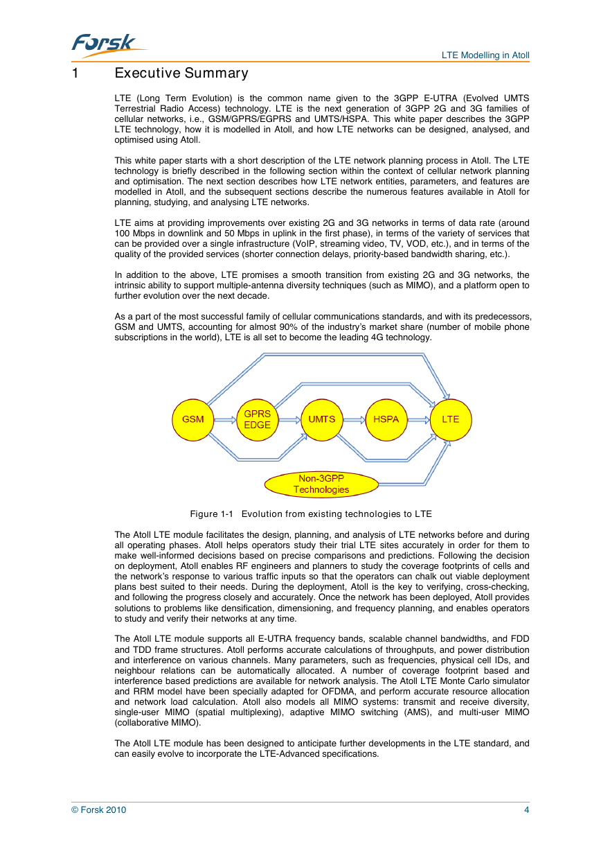
Figure 1-1 Evolution from existing technologies to LTE
The Atoll LTE module facilitates the design, planning, and analysis of LTE networks before and during
all operating phases. Atoll helps operators study their trial LTE sites accurately in order for them to
make well-informed decisions based on precise comparisons and predictions. Following the decision
on deployment, Atoll enables RF engineers and planners to study the coverage footprints of cells and
the network’s response to various traffic inputs so that the operators can chalk out viable deployment
plans best suited to their needs. During the deployment, Atoll is the key to verifying, cross-checking,
and following the progress closely and accurately. Once the network has been deployed, Atoll provides
solutions to problems like densification, dimensioning, and frequency planning, and enables operators
to study and verify their networks at any time.
The Atoll LTE module supports all E-UTRA frequency bands, scalable channel bandwidths, and FDD
and TDD frame structures. Atoll performs accurate calculations of throughputs, and power distribution
and interference on various channels. Many parameters, such as frequencies, physical cell IDs, and
neighbour relations can be automatically allocated. A number of coverage footprint based and
interference based predictions are available for network analysis. The Atoll LTE Monte Carlo simulator
and RRM model have been specially adapted for OFDMA, and perform accurate resource allocation
and network load calculation. Atoll also models all MIMO systems: transmit and receive diversity,
single-user MIMO (spatial multiplexing), adaptive MIMO switching (AMS), and multi-user MIMO
(collaborative MIMO).
The Atoll LTE module has been designed to anticipate further developments in the LTE standard, and
can easily evolve to incorporate the LTE-Advanced specifications.
© Forsk 2010
4
�
LTE Modelling in Atoll
2
LTE Network Planning Process in Atoll
In the most frequent cases, LTE networks will start out as trial cells in urban areas located on existing
2G or 3G sites, and sharing a 3G UTRA frequency band and carrier already available to the operator.
These trial sites will help operators assess the technology and determine the added value that LTE will
bring to the existing network. One of the crucial tests for any operator will be to study the interworking
and co-existence of 2G and 3G with LTE in terms of sharing the available frequency spectrum, inter-
network interference, and inter-RAT handovers. Once on air, these trial sites will provide high data rate
access to users in their coverage areas. In the long run, LTE cells will either replace existing
technology cells in urban areas or provide an additional coverage layer on top of the existing
technology layer(s).
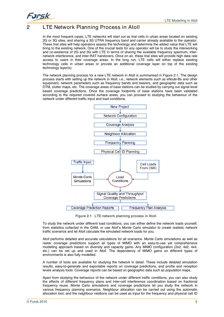
The network planning process for a new LTE network in Atoll is summarised in Figure 2-1. The design
process starts with setting up the network in Atoll, i.e., network elements such as eNode-Bs and other
equipment, network parameters such as frequency bands and bearers, and geographic data such as
DTM, clutter maps, etc. The coverage areas of base stations can be studied by carrying out signal level
based coverage predictions. Once the coverage footprints of base stations have been validated
according to the required covered surface areas, you can proceed to studying the behaviour of the
network under different traffic input and load conditions.
Figure 2-1 LTE network planning process in Atoll
To study the network under different load conditions, you can either define the network loads yourself,
from statistics collected in the OAM, or use Atoll’s Monte Carlo simulator to create realistic network
traffic scenarios and let Atoll calculate the simulated network loads for you.
Atoll performs detailed and accurate calculations for all scenarios. Monte Carlo simulations as well as
raster coverage predictions support all types of MIMO with an easy-to-use yet comprehensive
modelling approach based on diversity and capacity gains. Any MIMO configuration (2x2, 4x2, 4x4,
etc.) can be set up and used in Atoll. The dependency of MIMO gains on different types of
environments is also fully modelled.
A number of tools are available for studying the network in detail. These include detailed simulation
results, easy-to-generate and exportable reports on coverage predictions, and profile and reception
levels analysis tools. Coverage reports can be based on geographic data such as population maps.
Apart from studying the behaviour of the network under different traffic conditions, you can also study
the effects of different frequency plans and inter-cell interference coordination based on fractional
frequency reuse. Monte Carlo simulations and coverage predictions let you study the network in
various frequency planning scenarios. Neighbour allocation can be carried out using the automatic
allocation tool, and the neighbour relations can be used as input for the frequency and physical cell ID
© Forsk 2010
5
�
LTE Modelling in Atoll
allocation tools. You can also use the search tool to verify the frequency and physical cell ID allocation
of your network.
Atoll allows you to work with different technology networks in the same session, letting you link network
elements from one technology document to another, compare raster coverage predictions, and carry
out inter-technology neighbour allocation, i.e., inter-RAT handovers. The next release of Atoll will also
allow you to study the effect of inter-network interference, so that you can accurately analyse the effect
of sharing the available spectrum between different technology networks.
3
3GPP LTE
LTE, or Long Term Evolution, is the next generation of 2G and 3G families of 3GPP cellular networks.
It is the long term evolution proposed by the 3GPP for existing UMTS Terrestrial Radio Access
Networks (UTRAN). LTE corresponds to the Release 8 of the 3GPP specifications.
The aim of the 3GPP LTE project is to achieve:
•
•
•
•
•
•
High downlink and uplink data rates: from 100 to more than 300 Mbps in downlink with SISO
and 4x4 MIMO, respectively, and up to 80 Mbps in uplink. These values are provided for FDD,
64QAM, and 20 MHz channel bandwidth.
Scalable channel bandwidths: from 1.4 to 20 MHz in uplink and downlink.
Improved spectral efficiency: three to four times in downlink and two to three times in uplink with
respect to the Release 6.
Low latency: less than 5 ms latency.
Performance optimisation for different mobile speeds: optimised for speeds from 0 to 15 km/h,
high performance for 15 to 120 km/h, and operative from 120 to 350 km/h.
System architecture evolution towards a common all-IP platform and co-existence with legacy
standards.
3GPP LTE is among the three standards which will probably be referred to as the 4G technologies:
•
•
•
3GPP LTE
3GPP2 UMB (ultra-mobile broadband, which is the Rev. C of the CDMA2000 EV-DO standard)
Mobile WiMAX™ (IEEE 802.16e, IEEE 802.16m, and WiBRO)
All the 4G technologies have common goals and are all based on OFDM. LTE uses SOFDMA in
downlink and SC-FDMA in uplink. The physical as well as higher layer characteristics of LTE are
described in the 36 series of the 3GPP specifications, titled “Evolved UTRA aspects.”
The LTE standard proposes certain flexibility, in terms of spectrum and resource usage, which will
make it possible to offer a large variety of services in an LTE network. Services other than mobile
internet access and VoIP-based telephony could include broadcast (MBSFN), wireless DSL or xDSL
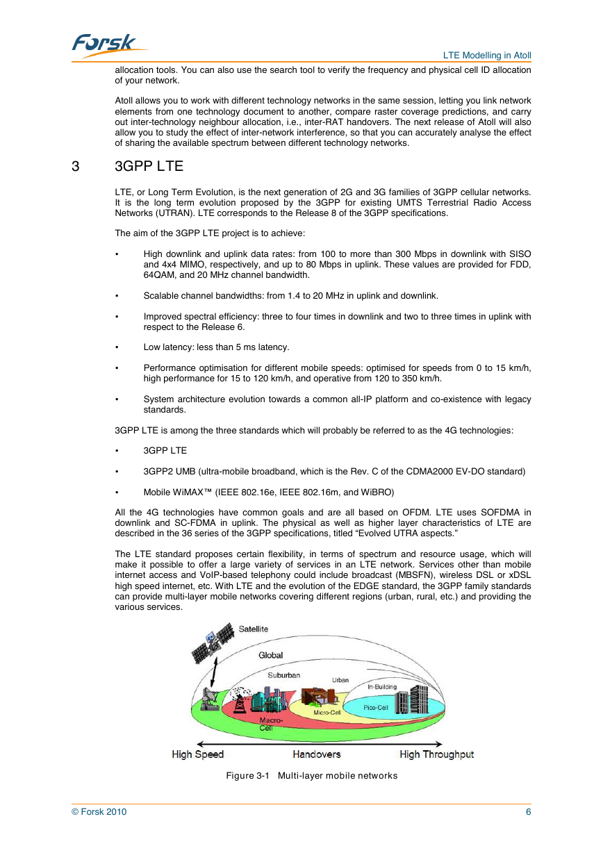
high speed internet, etc. With LTE and the evolution of the EDGE standard, the 3GPP family standards
can provide multi-layer mobile networks covering different regions (urban, rural, etc.) and providing the
various services.
Figure 3-1 Multi-layer mobile networks
© Forsk 2010
6
�
LTE Modelling in Atoll
3.1
The 3GPP Standards Family
Most cellular mobile networks around the world are based on technology standards from 3GPP, with
more than three billion subscribers registered worldwide. LTE is an evolution of the existing 2G and 3G
technologies towards a new radio access technology and an evolved packet core (System Architecture
Evolution – SAE). LTE correspond to the Release 8 of the 3GPP specifications series.
Release ’99 contains all the features needed to meet the IMT-2000 requirements as defined by the ITU,
i.e., circuit-switched voice services and data services over both packet-switched and circuit-switched
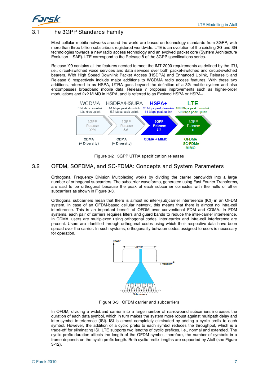
bearers. With High Speed Downlink Packet Access (HSDPA) and Enhanced Uplink, Release 5 and
Release 6 respectively include major additions to WCDMA radio access features. With these two
additions, referred to as HSPA, UTRA goes beyond the definition of a 3G mobile system and also
encompasses broadband mobile data. Release 7 proposes improvements such as higher-order
modulations and 2x2 MIMO in HSPA, and is referred to as Evolved HSPA or HSPA+.
Figure 3-2 3GPP UTRA specification releases
3.2
OFDM, SOFDMA, and SC-FDMA: Concepts and System Parameters
Orthogonal Frequency Division Multiplexing works by dividing the carrier bandwidth into a large
number of orthogonal subcarriers. The subcarrier waveforms, generated using Fast Fourier Transforms,
are said to be orthogonal because the peak of each subcarrier coincides with the nulls of other
subcarriers as shown in Figure 3-3.
Orthogonal subcarriers mean that there is almost no inter-(sub)carrier interference (ICI) in an OFDM
system. In case of an OFDM-based cellular network, this means that there is almost no intra-cell
interference. This is an important benefit of OFDM over conventional FDM and CDMA. In FDM
systems, each pair of carriers requires filters and guard bands to reduce the inter-carrier interference.
In CDMA, users are multiplexed using orthogonal codes. Inter-carrier and intra-cell interference are
present. Users are identified through orthogonal codes using which their respective data have been
spread over the carrier. In such systems, orthogonality between codes assigned to users is necessary
for operation.
Figure 3-3 OFDM carrier and subcarriers
In OFDM, dividing a wideband carrier into a large number of narrowband subcarriers increases the
duration of each data symbol, which in turn makes the system more robust against multipath delay and
inter-symbol interference (ISI). ISI is almost completely eliminated by adding a cyclic prefix to each
symbol. However, the addition of a cyclic prefix to each symbol reduces the throughput, which is a
trade-off for eliminating ISI. LTE supports two lengths of cyclic prefixes, i.e., normal and extended. The
cyclic prefix duration affects the length of the OFDM symbol, therefore, the number of symbols in a
frame depends on the cyclic prefix length. Both cyclic prefix lengths are supported by Atoll (see Figure
3-12).
© Forsk 2010
7
�
LTE Modelling in Atoll
Figure 3-4 Symbol duration for wideband carrier
Figure 3-5 Symbol duration for narrowband subcarriers
Figure 3-6 OFDM symbol and cyclic prefix
The union of frequency (subcarriers) and time (OFDM symbols) dimensions gives a two-dimensional
OFDM resource plane, as shown in Figure 3-7. The smallest resource allocation unit in LTE is a
Resource Block (RB), which has a width of 180 kHz in the frequency domain (a frequency block), and
0.5 ms in the time domain (a slot). The width of a resource block is a system-level constant. A resource
block of 180 kHz can comprise 12 or 24 subcarriers, depending on the subcarrier width used. Two
subcarrier widths are possible in LTE: 15 and 7.5 kHz. A slot in the time domain can contain a number
of OFDM symbols, which depends on the cyclic prefix length: normal or extended.
Figure 3-7 OFDM frame
The option of 7.5-kHz subcarrier spacing is available for supporting multi-media broadcast services
(MBSFN). Narrower subcarrier spacing results in longer symbol durations and higher robustness in
multipath environments, and allows for recombination of signals received from more than one eNode-B.
LTE supports two types of frame structures, one for FDD and the other for TDD networks (Figure 3-8).
Both frame structures are supported by Atoll. TDD frames can have variable DL-to-UL ratios which are
fully modelled in Atoll. An LTE frame is 10 ms long and contains 10 subframes of 1 ms each (1 TTI –
Transmission Time Interval), which in turn consist of two slots of 0.5 ms each.
© Forsk 2010
8
�


 2023年江西萍乡中考道德与法治真题及答案.doc
 2012年重庆南川中考生物真题及答案.doc
 2013年江西师范大学地理学综合及文艺理论基础考研真题.doc
 2020年四川甘孜小升初语文真题及答案I卷.doc
 2020年注册岩土工程师专业基础考试真题及答案.doc
 2023-2024学年福建省厦门市九年级上学期数学月考试题及答案.doc
 2021-2022学年辽宁省沈阳市大东区九年级上学期语文期末试题及答案.doc
 2022-2023学年北京东城区初三第一学期物理期末试卷及答案.doc
 2018上半年江西教师资格初中地理学科知识与教学能力真题及答案.doc
 2012年河北国家公务员申论考试真题及答案-省级.doc
 2020-2021学年江苏省扬州市江都区邵樊片九年级上学期数学第一次质量检测试题及答案.doc
 2022下半年黑龙江教师资格证中学综合素质真题及答案.doc