SL-845GLI / 845GLI-L
Chapter 1 Specifications
Chapter 1 Specification
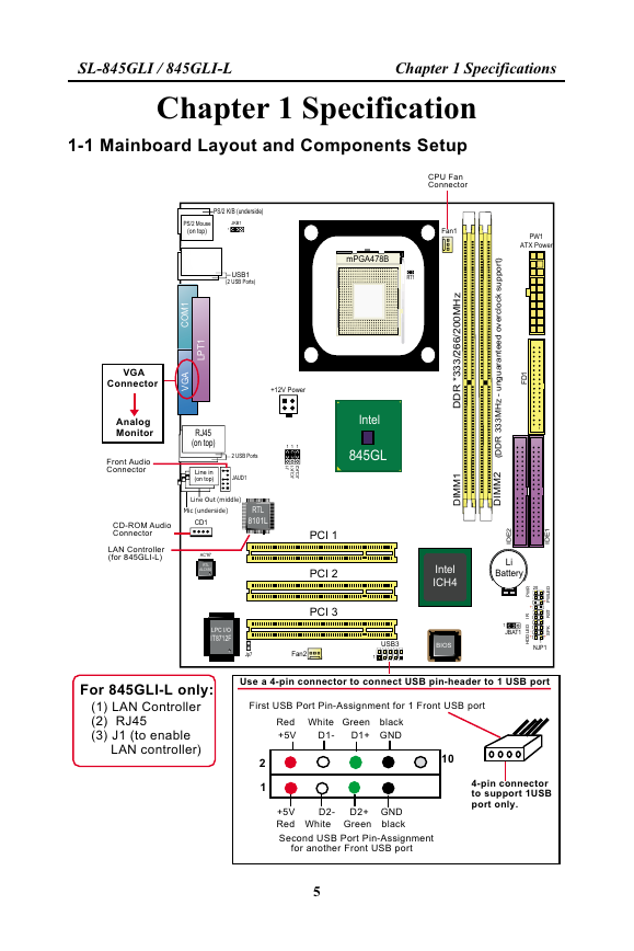
1-1 Mainboard Layout and Components Setup
PW1
ATX Power
1
D
F
1
)
t
r
o
p
p
u
s
k
c
o
c
r
e
v
o
l
d
e
e
t
n
a
r
a
u
g
n
u
-
z
H
M
3
3
3
R
D
D
(
2
M
M
D
I
1
E
D
I
2
E
D
I
Li
Battery
20
R
W
P
+
R
I
D
E
L
W
P
-
+
T
S
R
K
P
S
+
D
E
L
D
D
H
-
+
1
NJP1
PS/2 K/B (underside)
PS/2 Mouse
(on top)
JKB1
1
USB1
(2 USB Ports)
mPGA478B
RT1
1
M
O
C
A
G
V
1
T
P
L
+12V Power
RJ45
(on top)
2 USB Ports
Line in
(on top)
JAUD1
1
1
1
1
J
1
K
L
C
J
2
K
L
C
J
Intel
845GL
VGA
Connector
Analog
Monitor
Front Audio
Connector
Line Out (middle)
Mic (underside)
CD-ROM Audio
Connector
LAN Controller
(for 845GLI-L)
CD1
AC'97
RTL
ALC650
RTL
8101L
PCI 1
PCI 2
PCI 3
CPU Fan
Connector
Fan1
z
H
M
0
0
2
/
6
6
2
/
3
3
3
*
R
D
D
1
M
M
D
I
Intel
ICH4
LPC I/O
IT8712F
Jp7
Fan2
USB3
1
BIOS
1
JBAT1
For 845GLI-L only:
(1) LAN Controller
(2) RJ45
(3) J1 (to enable
LAN controller)
Use a 4-pin connector to connect USB pin-header to 1 USB port
First USB Port Pin-Assignment for 1 Front USB port
Red White Green black
+5V
D1-
D1+
GND
10
4-pin connector
to support 1USB
port only.
2
1
+5V
Red
D2-
White
D2+
Green
GND
black
Second USB Port Pin-Assignment
for another Front USB port
5
�
SL-845GLI / 845GLI-L
Chapter 1 Specifications
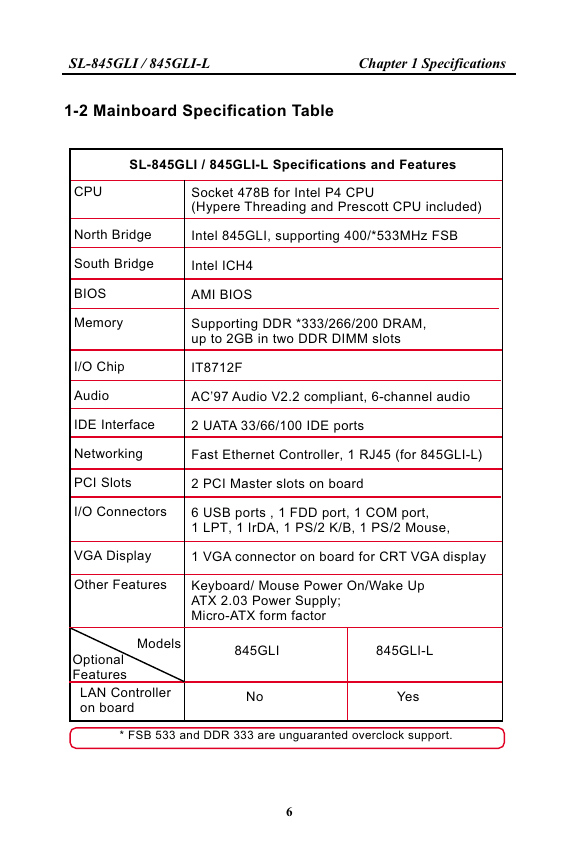
1-2 Mainboard Specification Table
SL-845GLI / 845GLI-L Specifications and Features
CPU
Socket 478B for Intel P4 CPU
(Hypere Threading and Prescott CPU included)
North Bridge
Intel 845GLI, supporting 400/*533MHz FSB
South Bridge
Intel ICH4
BIOS
Memory
AMI BIOS
Supporting DDR *333/266/200 DRAM,
up to 2GB in two DDR DIMM slots
I/O Chip
IT8712F
Audio
AC’97 Audio V2.2 compliant, 6-channel audio
IDE Interface
2 UATA 33/66/100 IDE ports
Networking
Fast Ethernet Controller, 1 RJ45 (for 845GLI-L)
PCI Slots
2 PCI Master slots on board
I/O Connectors
6 USB ports , 1 FDD port, 1 COM port,
1 LPT, 1 IrDA, 1 PS/2 K/B, 1 PS/2 Mouse,
VGA Display
1 VGA connector on board for CRT VGA display
Other Features
Keyboard/ Mouse Power On/Wake Up
ATX 2.03 Power Supply;
Micro-ATX form factor
Models
Optional
Features
LAN Controller
on board
845GLI
845GLI-L
No
Yes
* FSB 533 and DDR 333 are unguaranted overclock support.
6
�
SL-845GLI / 845GLI-L
Chapter 1 Specifications
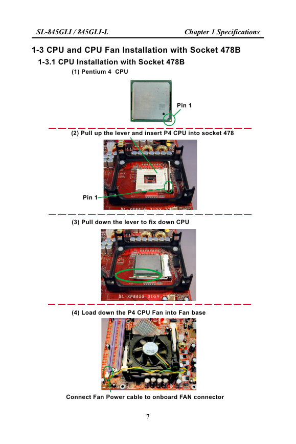
1-3 CPU and CPU Fan Installation with Socket 478B
1-3.1 CPU Installation with Socket 478B
(1) Pentium 4 CPU
Pin 1
(2) Pull up the lever and insert P4 CPU into socket 478
Pin 1
(3) Pull down the lever to fix down CPU
(4) Load down the P4 CPU Fan into Fan base
Connect Fan Power cable to onboard FAN connector
7
�
SL-845GLI / 845GLI-L
Chapter 1 Specifications
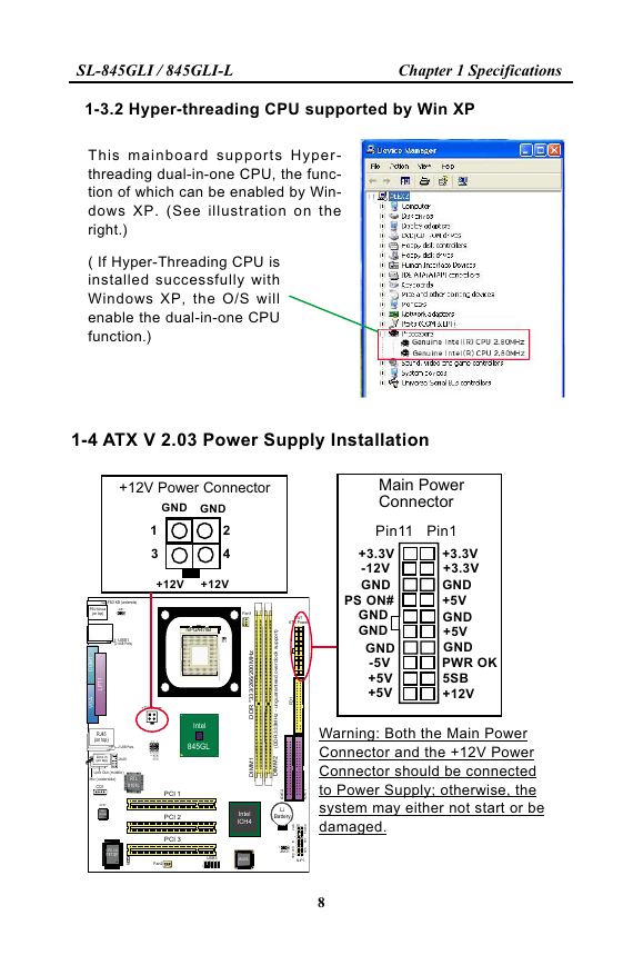
1-3.2 Hyper-threading CPU supported by Win XP
T h i s m a i n b o a r d s u p p o r t s H y p e r -
threading dual-in-one CPU, the func-
tion of which can be enabled by Win-
dows XP. (See illustration on the
right.)
( If Hyper-Threading CPU is
installed successfully with
Windows XP, the O/S will
enable the dual-in-one CPU
function.)
1-4 ATX V 2.03 Power Supply Installation
+12V Power Connector
GND GND
1
3
2
4
+12V
+12V
PS/2 K/B (underside)
PS/2 Mouse
(on top)
JKB1
1
USB1
(2 USB Ports)
mPGA478B
RT1
1
M
O
C
A
G
V
1
T
P
L
+12V Power
RJ45
(on top)
2 USB Ports
Line in
(on top)
JAUD1
1
1
1
1
J
1
K
L
C
J
2
K
L
C
J
RTL
8101L
Line Out (middle)
Mic (underside)
CD1
AC'97
RTL
ALC650
Intel
845GL
PCI 1
PCI 2
PCI 3
z
H
M
0
0
2
/
6
6
2
/
3
3
3
*
R
D
D
1
M
M
D
I
Intel
ICH4
LPC I/O
IT8712F
Jp7
Fan2
USB3
1
BIOS
1
JBAT1
D
E
L
D
D
H
-
+
Main Power
Connector
Pin11
Pin1
+3.3V
-12V
GND
PS ON#
GND
GND
GND
-5V
+5V
+5V
+3.3V
+3.3V
GND
+5V
GND
+5V
GND
PWR OK
5SB
+12V
Warning: Both the Main Power
Connector and the +12V Power
Connector should be connected
to Power Supply; otherwise, the
system may either not start or be
damaged.
Fan1
PW1
ATX Power
)
t
r
o
p
p
u
s
k
c
o
c
r
e
v
o
l
d
e
e
t
n
a
r
a
u
g
n
u
-
z
H
M
3
3
3
R
D
D
(
2
M
M
D
I
1
D
F
1
1
E
D
I
2
E
D
I
Li
Battery
20
R
W
P
+
R
I
D
E
L
W
P
-
+
T
S
R
K
P
S
+
1
NJP1
8
�
SL-845GLI / 845GLI-L
Chapter 1 Specifications
1-5 Jumper Settings
The following diagrams show the locations and settings of jumper blocks
on the mainboard.
JKB1:
Keyboard/Mouse
Power On / Wake Up
1-2 closed (default)
Disabled
2-3 closed
Enabled
1
1
PS/2 K/B (underside)
PS/2 Mouse
(on top)
JKB1
1
USB1
(2 USB Ports)
mPGA478B
RT1
1
M
O
C
A
G
V
1
T
P
L
+12V Power
RJ45
(on top)
2 USB Ports
Line in
(on top)
JAUD1
1
1
1
1
J
1
K
L
C
J
2
K
L
C
J
RTL
8101L
Line Out (middle)
Mic (underside)
CD1
AC'97
RTL
ALC650
Intel
845GL
PCI 1
PCI 2
PCI 3
z
H
M
0
0
2
/
6
6
2
/
3
3
3
*
R
D
D
1
M
M
D
I
Intel
ICH4
Fan1
PW1
ATX Power
l
)
t
r
o
p
p
u
s
k
c
o
c
r
e
v
o
d
e
e
t
n
a
r
a
u
g
n
u
-
z
H
M
3
3
3
R
D
D
(
1
D
F
1
2
M
M
D
I
1
E
D
I
2
E
D
I
Li
Battery
JBAT1
Clear CMOS
1-2 closed
(default)
To hold data
2-3 closed
To clear CMOS
1
1
LPC I/O
IT8712F
Jp7
Fan2
USB3
1
BIOS
1
JBAT1
20
R
W
P
+
R
I
D
E
L
W
P
-
+
T
S
R
K
P
S
+
D
E
L
D
D
H
-
+
1
NJP1
J1:
LAN Controller Select
(845GLI-L only)
1-2 closed
(default)
LAN controller enabled
1
1
(default)
CPU
Auto-
Detection
1
1
100MHz
(FSB400)
133MHz
*(FSB533)
200MHz
*(FSB800)
2-3 closed
LAN controller disabled
J
C
L
K
1
J
C
L
K
2
J
C
L
K
1
1
1
J
C
L
K
1
J
C
L
K
2
1
1
1
1
J
C
L
K
2
J
C
L
K
1
J
C
L
K
2
JCLK1&JCLK2: CPU Frequency Select
* FSB 533/800 is unguaranteed overclock support.
9
�
SL-845GLI / 845GLI-L
Chapter 1 Specifications
1-6 Other Connectors Setup
1-6.1 Front Audio Connector
PS/2 K/B (underside)
PS/2 Mouse
(on top)
JKB1
1
Fan1
PW1
ATX Power
This Mainboard is designed with a Front
Panel Audio connector “JAUD1” which
provides connection to your chassis.
1. When JAUD1 is set to 5-6 closed and
9-10 closed, this default setting
disables this connector and leaves the
Back Panel Audio enabled.
2 . To u s e t h i s F r o n t P a n e l A u d i o
Connector, please open all pins of
JAUD1 and connect it to your chassis.
JAUD1: Front Panel Audio Connector
Pin 10 RET L
Pin 9 FPOUT L
USB1
(2 USB Ports)
mPGA478B
RT1
1
M
O
C
A
G
V
1
T
P
L
+12V Power
RJ45
(on top)
2 USB Ports
Line in
(on top)
JAUD1
1
1
1
1
J
1
K
L
C
J
2
K
L
C
J
RTL
8101L
Line Out (middle)
Mic (underside)
CD1
AC'97
RTL
ALC650
/
z
H
M
0
0
2
6
6
2
3
3
3
*
R
D
D
/
Intel
845GL
PCI 1
PCI 2
PCI 3
1
M
M
D
I
Intel
ICH4
)
t
r
o
p
p
u
s
k
c
o
c
r
e
v
o
l
d
e
e
t
n
a
r
a
u
g
n
u
-
z
H
M
3
3
3
R
D
D
(
2
M
M
D
I
1
D
F
1
1
E
D
I
2
E
D
I
Li
Battery
LPC I/O
IT8712F
Jp7
Fan2
USB3
1
BIOS
1
JBAT1
20
R
W
P
+
R
I
D
E
L
W
P
-
+
T
S
R
K
P
S
+
D
E
L
D
D
H
-
+
1
NJP1
Pin 7 (Key)
Jp7
RT1
Pin 6 RET R
Pin 5 FPOUT R
Pin 4 Aud Vcc
Pin 3 Mic VREF
Pin 2 Aud GND
Pin 1 Mic In
1-6.2 Thermal Resistor and Connector
1. Resistor RT1: A thermal resistor is
mounted by default to connector RT1 so
as to detect the external CPU temperature
. What RT1 does is to transmit the thermal
signal to Hardware Monitor.
RT1
RT1 is mounted with Ther-
mal Resistor by default for
detecting the external CPU
temperature.
2. Connector Jp7: A thermal cable is needed
to connect Jp7 to on-board devices such
as HDD, Graphics card etc., so as to
detect the temperature generated therein.
Please connect the end (a) of the thermal
cable to Jp7, and tape another end (b) of
thermal cable on to the device which you
want to monitor. After you have finished
the thermal cable installation, you will see
the detected temperature in BIOS setup
or Hardware Monitor utility.
Jp7
To Jp1
To Devices
(Optional)
Thermal Cable
10
�
SL-845GLI / 845GLI-L
Chapter 1 Specifications
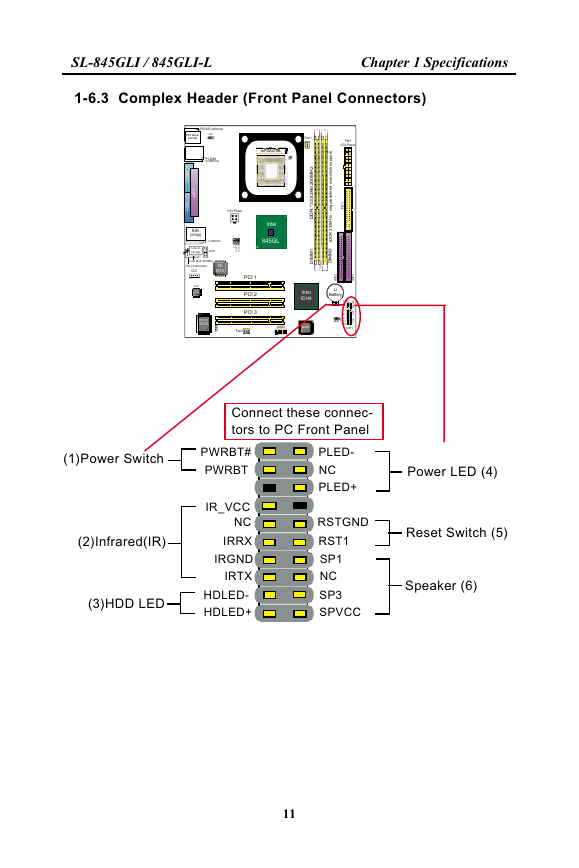
1-6.3 Complex Header (Front Panel Connectors)
PS/2 K/B (underside)
PS/2 Mouse
(on top)
JKB1
1
USB1
(2 USB Ports)
mPGA478B
RT1
1
M
O
C
A
G
V
1
T
P
L
+12V Power
RJ45
(on top)
2 USB Ports
Line in
(on top)
JAUD1
1
1
1
1
J
1
K
L
C
J
2
K
L
C
J
RTL
8101L
Line Out (middle)
Mic (underside)
CD1
AC'97
RTL
ALC650
/
z
H
M
0
0
2
6
6
2
3
3
3
*
R
D
D
/
Intel
845GL
PCI 1
PCI 2
PCI 3
1
M
M
D
I
Intel
ICH4
LPC I/O
IT8712F
Jp7
Fan2
1
USB3
BIOS
1
JBAT1
D
E
L
D
D
H
-
+
Fan1
PW1
ATX Power
l
)
t
r
o
p
p
u
s
k
c
o
c
r
e
v
o
d
e
e
t
n
a
r
a
u
g
n
u
-
z
H
M
3
3
3
R
D
D
(
2
M
M
D
I
1
D
F
1
1
E
D
I
2
E
D
I
Li
Battery
20
R
W
P
+
R
I
D
E
L
W
P
-
+
T
S
R
K
P
S
+
1
NJP1
Connect these connec-
tors to PC Front Panel
(1)Power Switch
(2)Infrared(IR)
(3)HDD LED
PWRBT#
PWRBT
IR_VCC
NC
IRRX
IRGND
IRTX
HDLED-
HDLED+
PLED-
NC
PLED+
RSTGND
RST1
SP1
NC
SP3
SPVCC
Power LED (4)
Reset Switch (5)
Speaker (6)
11
�




 2023年江西萍乡中考道德与法治真题及答案.doc
 2012年重庆南川中考生物真题及答案.doc
 2013年江西师范大学地理学综合及文艺理论基础考研真题.doc
 2020年四川甘孜小升初语文真题及答案I卷.doc
 2020年注册岩土工程师专业基础考试真题及答案.doc
 2023-2024学年福建省厦门市九年级上学期数学月考试题及答案.doc
 2021-2022学年辽宁省沈阳市大东区九年级上学期语文期末试题及答案.doc
 2022-2023学年北京东城区初三第一学期物理期末试卷及答案.doc
 2018上半年江西教师资格初中地理学科知识与教学能力真题及答案.doc
 2012年河北国家公务员申论考试真题及答案-省级.doc
 2020-2021学年江苏省扬州市江都区邵樊片九年级上学期数学第一次质量检测试题及答案.doc
 2022下半年黑龙江教师资格证中学综合素质真题及答案.doc