Arm Debug Interface Architecture Specification ADIv5.0 to ADIv5.2
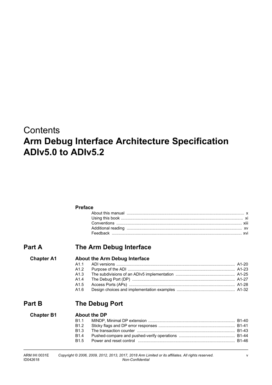
Contents
Preface
About this manual
Intended audience
Using this book
Conventions
Typographic conventions
Signals
Timing diagrams
Numbers
Pseudocode descriptions
Additional reading
Arm publications
Other publications
Feedback
Feedback on this book
The Arm Debug Interface
About the Arm Debug Interface
A1.1 ADI versions
A1.1.1 About the minor versions of ADIv5
A1.2 Purpose of the ADI
A1.2.1 Embedded core debug functionality
A1.2.2 System debug functionality
A1.2.3 Compatibility between CoreSight and Arm debug interfaces
A1.3 The subdivisions of an ADIv5 implementation
A1.3.1 Connections to the ADI
A1.3.2 Accessing the DAP
A1.4 The Debug Port (DP)
A1.5 Access Ports (APs)
A1.5.1 Using the Debug Port to access Access Ports
A1.5.2 Guide to the detailed description of a MEM-AP
A1.5.3 Guide to the detailed description of a JTAG-AP
A1.5.4 Using the AP to access debug resources
A1.6 Design choices and implementation examples
A1.6.1 Choices for the DP
A1.6.2 Choices for the APs
The Debug Port
About the DP
B1.1 MINDP, Minimal DP extension
B1.2 Sticky flags and DP error responses
B1.3 The transaction counter
B1.4 Pushed-compare and pushed-verify operations
B1.5 Power and reset control
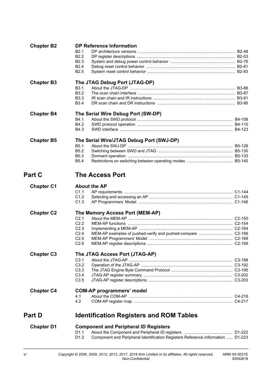
DP Reference Information
B2.1 DP architecture versions
B2.1.1 DP architecture versions summary
B2.1.2 DP architecture version 0 (DPv0) address map
B2.1.3 DP architecture version 1 (DPv1) address map
B2.1.4 DP architecture version 2 (DPv2) address map
B2.1.5 Register maps, and accesses to reserved addresses
B2.2 DP register descriptions
B2.2.1 ABORT, Abort register
B2.2.2 CTRL/STAT, Control/Status register
B2.2.3 DLCR, Data Link Control register
B2.2.4 DLPIDR, Data Link Protocol Identification register
B2.2.5 DPIDR, Debug Port Identification register
B2.2.6 EVENTSTAT, Event Status register
B2.2.7 RDBUFF, Read Buffer register
B2.2.8 RESEND, Read Resend register
B2.2.9 SELECT, AP Select register
B2.2.10 TARGETID, Target Identification register
B2.2.11 TARGETSEL, Target Selection register
B2.3 System and debug power control behavior
B2.3.1 The DAP power domains model
B2.3.2 Power control requirements and operation
B2.3.3 Emulation of powerdown
B2.3.4 Emulation of power control
B2.4 Debug reset control behavior
B2.4.1 Emulation of debug reset request
B2.4.2 Limitations of CDBGRSTREQ and CDBGRSTACK
B2.5 System reset control behavior
B2.5.1 Limitations of system reset control
The JTAG Debug Port (JTAG-DP)
B3.1 About the JTAG-DP
B3.2 The scan chain interface
B3.2.1 DAP elements
B3.2.2 Physical connection to the JTAG-DP
B3.2.3 The Debug TAP State Machine (DBGTAPSM)
B3.3 IR scan chain and IR instructions
B3.3.1 Required IR instructions
B3.3.2 IMPLEMENTATION DEFINED extensions to the IR instruction set
B3.3.3 IR, JTAG-DP Instruction Register
B3.4 DR scan chain and DR instructions
B3.4.1 ABORT, JTAG-DP Abort register
B3.4.2 BYPASS, JTAG-DP Bypass register
B3.4.3 DPACC and APACC, JTAG-DP DP and AP Access registers
B3.4.4 IDCODE, the JTAG TAP ID register
The Serial Wire Debug Port (SW-DP)
B4.1 About the SWD protocol
B4.1.1 Basic operation
B4.1.2 SWD protocol versions
B4.1.3 Line turnaround
B4.1.4 Idle cycles
B4.1.5 Bit order
B4.1.6 Parity
B4.1.7 Limitations of multi-drop
B4.2 SWD protocol operation
B4.2.1 Successful write operation (OK response)
B4.2.2 Successful read operation (OK response)
B4.2.3 WAIT response to read or write operation request
B4.2.4 FAULT response to read or write operation request
B4.2.5 Protocol error response
B4.2.6 Sticky overrun behavior
B4.2.7 SW-DP write buffering
B4.2.8 Summary of target responses
B4.2.9 Summary of host responses
B4.3 SWD interface
B4.3.1 Line interface
B4.3.2 Line pull-up
B4.3.3 Connection and line reset sequence
B4.3.4 Target selection protocol, SWD protocol version 2
The Serial Wire/JTAG Debug Port (SWJ-DP)
B5.1 About the SWJ-DP
B5.1.1 SWJ-DP structure
B5.1.2 Limitations when reusing pins
B5.2 Switching between SWD and JTAG
B5.2.1 The Switching Mechanism
B5.2.2 Switching from JTAG to SWD operation
B5.2.3 Switching from SWD to JTAG operation
B5.3 Dormant operation
B5.3.1 Using the dormant state outside of SWJ-DP
B5.3.2 Switching from JTAG to dormant state
B5.3.3 Switching from SWD to dormant state
B5.3.4 Leaving dormant state
B5.4 Restrictions on switching between operating modes
The Access Port
About the AP
C1.1 AP requirements
C1.2 Selecting and accessing an AP
C1.2.1 Stalling accesses
C1.3 AP Programmers’ Model
C1.3.1 Summary
C1.3.2 IDR, Identification Register
The Memory Access Port (MEM-AP)
C2.1 About the MEM-AP
C2.1.1 The programmers’ model for debug register access
C2.1.2 Selecting and accessing the MEM-AP
C2.1.3 The MEM-AP registers
C2.1.4 MEM-AP register accesses and memory accesses
C2.2 MEM-AP functions
C2.2.1 Enabling access to the connected debug device or memory system
C2.2.2 Auto-incrementing the Transfer Address Register (TAR)
C2.2.3 Stalling accesses
C2.2.4 Response to debug component errors
C2.2.5 Variable access size for memory accesses
C2.2.6 Byte lanes
C2.2.7 Packed transfers
C2.2.8 Slave Memory Ports
C2.2.9 Software access control
C2.3 Implementing a MEM-AP
C2.3.1 IMPLEMENTATION DEFINED features of a MEM-AP implementation
C2.3.2 MEM-AP implementation requirements
C2.3.3 MEM-AP Extensions
C2.4 MEM-AP examples of pushed-verify and pushed-compare
C2.4.1 Example of using a pushed-verify operation on a MEM-AP
C2.4.2 Example of using a pushed-find operation on a MEM-AP
C2.4.3 Example of using the transaction counter for a pushed-compare operation on a MEM-AP
C2.5 MEM-AP Programmers’ Model
C2.6 MEM-AP register descriptions
C2.6.1 BASE, Debug Base Address register
C2.6.2 BD0-BD3, Banked Data registers
C2.6.3 CFG, Configuration register
C2.6.4 CSW, Control/Status Word register
C2.6.5 DRW, Data Read/Write register
C2.6.6 MBT, Memory Barrier Transfer register
C2.6.7 TAR, Transfer Address Register
The JTAG Access Port (JTAG-AP)
C3.1 About the JTAG-AP
C3.1.1 Selecting and accessing the JTAG-AP
C3.1.2 Logical structure of the JTAG-AP
C3.1.3 JTAG port signals
C3.2 Operation of the JTAG-AP
C3.2.1 Stalling accesses
C3.2.2 Resetting connected JTAG devices or subsystems
C3.2.3 Pushed transaction and transaction counter support
C3.3 The JTAG Engine Byte Command Protocol
C3.3.1 The encoding of the TMS packet
C3.3.2 The encoding of the TDI_TDO packet
C3.3.3 Response bytes from a TDI_TDO packet
C3.4 JTAG-AP register summary
C3.5 JTAG-AP register descriptions
C3.5.1 BRFIFO1-BRFIFO4, Byte FIFO registers for read access
C3.5.2 BWFIFO1-BWFIFO4, Byte FIFO registers for write access
C3.5.3 CSW, Control/Status Word Register
C3.5.4 PSEL, Port Select register
C3.5.5 PSTA, Port Status Register
COM-AP programmers’ model
4.1 About the COM-AP
4.2 COM-AP register map
4.2.1 DP abort
4.2.2 IDR, Identification Register
Identification Registers and ROM Tables
Component and Peripheral ID Registers
D1.1 About the Component and Peripheral ID registers
D1.2 Component and Peripheral Identification Registers Reference Information
D1.2.1 CIDR0-CIDR3, Component Identification Registers
D1.2.2 PIDR0-PIDR7, Peripheral Identification Registers
D1.3 Legacy Peripheral ID layout
About ROM Tables
D2.1 ROM Tables Overview
D2.2 ROM Table Types
D2.3 Component and Peripheral ID Registers for ROM Tables
D2.3.1 Identifying the debug SoC or platform
D2.4 The component address
D2.5 Location of the ROM Table
D2.6 ROM Table hierarchies
D2.6.1 Peripheral ID Registers in lower-level ROM Tables
D2.6.2 Component Revision Numbers
D2.6.3 Prohibited ROM Table references
Class 0x1 ROM Tables
D3.1 About Class 0x1 ROM Tables
D3.2 Class 0x1 ROM Table summary
D3.2.1 Class 0x1 ROM Table Layout
D3.2.2 ROM Table entries that are marked not present
D3.3 Use of power domain IDs
D3.3.1 Power domain entries
D3.3.2 Algorithm to discover power domain IDs
D3.4 Register Descriptions
D3.4.1 CIDR0-CIDR3, Component Identification Registers
D3.4.2 MEMTYPE, Memory Type Register
D3.4.3 PIDR0-PIDR7, Peripheral Identification Registers
D3.4.4 ROMENTRY, Class 0x1 ROM Table entries
Class 0x9 ROM Tables
D4.1 About Class 0x9 ROM Tables
D4.2 Class 0x9 ROM Table summary
D4.2.1 Class 0x9 ROM Table Layout
D4.2.2 ROM Table entries that are marked not present
D4.3 Use of power domain IDs
D4.3.1 Power domain entries
D4.3.2 Algorithm to discover power domain IDs
D4.3.3 Debug power requests
D4.3.4 System power requests
D4.4 Reset control
D4.4.1 Debug reset control
D4.4.2 System reset control
D4.5 Register descriptions
D4.5.1 AUTHSTATUS, Authentication Status Register
D4.5.2 CIDR0-CIDR3, Component Identification Registers
D4.5.3 CLAIMSET and CLAIMCLR, Claim Tag Set Register and Claim Tag Clear Register
D4.5.4 DBGPCR, Debug Power Control Registers
D4.5.5 DBGPSR, Debug Power Status Registers
D4.5.6 DBGRSTAR, Debug Reset Acknowledge Register
D4.5.7 DBGRSTRR, Debug Reset Request Register
D4.5.8 DEVAFF0-DEVAFF1, Device Affinity Registers
D4.5.9 DEVARCH, Device Architecture Register
D4.5.10 DEVID, Device Configuration Register
D4.5.11 DEVID1-DEVID2, Device Configuration Registers
D4.5.12 DEVTYPE, Device Type Register
D4.5.13 ITCTRL, Integration Mode Control Register
D4.5.14 LAR and LSR, Software Lock Access Register and Software Lock Status Register
D4.5.15 PIDR0-PIDR7, Peripheral Identification Registers
D4.5.16 PRIDR0, Power Request ID Register 0
D4.5.17 ROMENTRY, Class 0x9 ROM Table entries
D4.5.18 SYSPCR, Debug Power Control Registers
D4.5.19 SYSPSR, System Power Status Registers
D4.5.20 SYSRSTAR, System Reset Acknowledge Register
D4.5.21 SYSRSTRR, System Reset Request Register
Appendixes
Standard Memory Access Port Definitions
E1.1 Introduction
E1.2 AMBA AXI3 and AXI4
E1.2.1 CSW register implementation
E1.3 AMBA AXI4 with ACE-Lite
E1.3.1 CSW register implementation
E1.3.2 MBT register implementation
E1.4 AMBA AHB3
E1.4.1 CSW register implementation
E1.5 AMBA AHB5
E1.5.1 CSW register implementation
E1.6 AMBA APB2 and APB3
E1.6.1 CSW register implementation
E1.7 AMBA APB4
E1.7.1 CSW register implementation
Cross-over with the Arm Architecture
E2.1 Introduction
E2.2 Armv6-M, Armv7-M, and Armv8-M architecture profiles
E2.3 Armv7-A without Large Physical Address Extension, Armv7-R, and Armv8-R
E2.4 Armv7-A with Large Physical Address Extension, and Armv8-A
E2.5 Summary of the requirements for ADIv5 implementations
Pseudocode Definition
E3.1 About Arm pseudocode
E3.1.1 General limitations of Arm pseudocode
E3.2 Data types
E3.2.1 General data type rules
E3.2.2 Bitstrings
E3.2.3 Integers
E3.2.4 Reals
E3.2.5 Booleans
E3.2.6 Enumerations
E3.2.7 Lists
E3.2.8 Arrays
E3.3 Expressions
E3.3.1 General expression syntax
E3.3.2 Operators and functions - polymorphism and prototypes
E3.3.3 Precedence rules
E3.4 Operators and built-in functions
E3.4.1 Operations on generic types
E3.4.2 Operations on Booleans
E3.4.3 Bitstring manipulation
E3.4.4 Arithmetic
E3.5 Statements and program structure
E3.5.1 Simple statements
E3.5.2 Compound statements
E3.5.3 Comments
Glossary


 2023年江西萍乡中考道德与法治真题及答案.doc
 2012年重庆南川中考生物真题及答案.doc
 2013年江西师范大学地理学综合及文艺理论基础考研真题.doc
 2020年四川甘孜小升初语文真题及答案I卷.doc
 2020年注册岩土工程师专业基础考试真题及答案.doc
 2023-2024学年福建省厦门市九年级上学期数学月考试题及答案.doc
 2021-2022学年辽宁省沈阳市大东区九年级上学期语文期末试题及答案.doc
 2022-2023学年北京东城区初三第一学期物理期末试卷及答案.doc
 2018上半年江西教师资格初中地理学科知识与教学能力真题及答案.doc
 2012年河北国家公务员申论考试真题及答案-省级.doc
 2020-2021学年江苏省扬州市江都区邵樊片九年级上学期数学第一次质量检测试题及答案.doc
 2022下半年黑龙江教师资格证中学综合素质真题及答案.doc