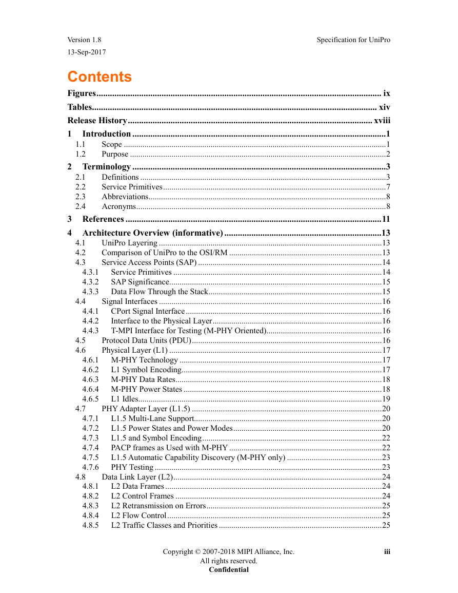
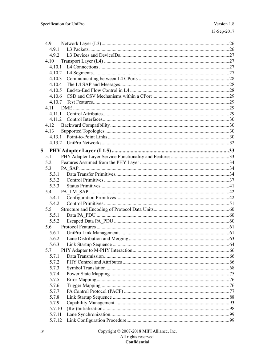
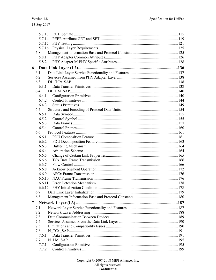
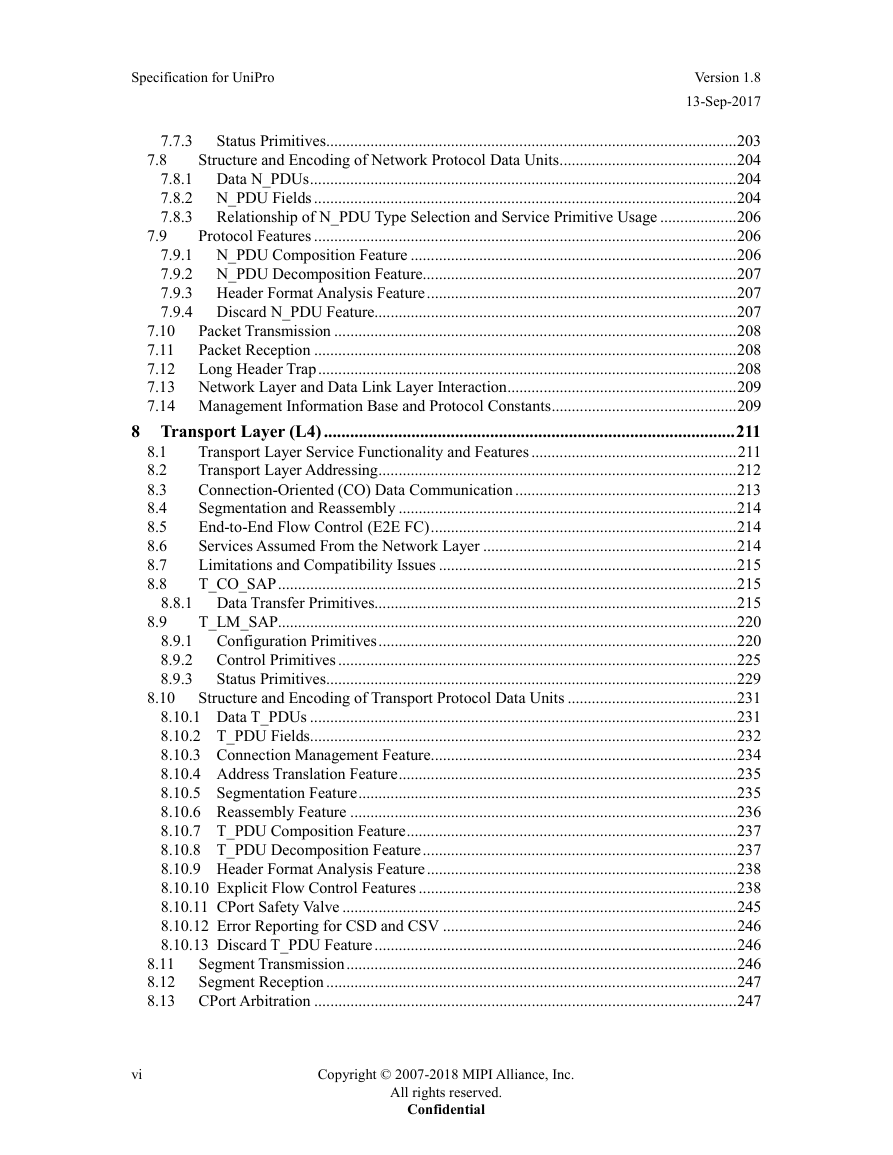
Contents
Figures
Tables
1 Introduction
1.1 Scope
1.2 Purpose
2 Terminology
2.1 Definitions
2.2 Service Primitives
2.3 Abbreviations
2.4 Acronyms
3 References
4 Architecture Overview (informative)
4.1 UniPro Layering
4.2 Comparison of UniPro to the OSI/RM
4.3 Service Access Points (SAP)
4.3.1 Service Primitives
4.3.2 SAP Significance
4.3.3 Data Flow Through the Stack
4.4 Signal Interfaces
4.4.1 CPort Signal Interface
4.4.2 Interface to the Physical Layer
4.4.3 T-MPI Interface for Testing (M-PHY Oriented)
4.5 Protocol Data Units (PDU)
4.6 Physical Layer (L1)
4.6.1 M-PHY Technology
4.6.1.1 Supported M-PHY Capabilities
4.6.2 L1 Symbol Encoding
4.6.2.1 M-PHY and Symbol Encoding
4.6.3 M-PHY Data Rates
4.6.4 M-PHY Power States
4.6.5 L1 Idles
4.7 PHY Adapter Layer (L1.5)
4.7.1 L1.5 Multi-Lane Support
4.7.1.1 L1.5 Multi-Lane Features for M-PHY
4.7.2 L1.5 Power States and Power Modes
4.7.2.1 L1.5 Controlling Power Modes for M-PHY
4.7.3 L1.5 and Symbol Encoding
4.7.4 PACP frames as Used with M-PHY
4.7.5 L1.5 Automatic Capability Discovery (M-PHY only)
4.7.6 PHY Testing
4.8 Data Link Layer (L2)
4.8.1 L2 Data Frames
4.8.2 L2 Control Frames
4.8.3 L2 Retransmission on Errors
4.8.4 L2 Flow Control
4.8.5 L2 Traffic Classes and Priorities
4.8.5.1 Frame Preemption
4.8.5.2 Single-TC Devices
4.9 Network Layer (L3)
4.9.1 L3 Packets
4.9.1.1 Short Header Packets
4.9.1.2 Long Header Packets
4.9.2 L3 Devices and DeviceIDs
4.10 Transport Layer (L4)
4.10.1 L4 Connections
4.10.2 L4 Segments
4.10.2.1 Short Header Segments
4.10.3 Communicating between L4 CPorts
4.10.4 The L4 SAP and Messages
4.10.5 End-to-End Flow Control in L4
4.10.6 CSD and CSV Mechanisms within a CPort
4.10.7 Test Features
4.11 DME
4.11.1 Control Attributes
4.11.2 Control Interfaces
4.12 Backward Compatibility
4.13 Supported Topologies
4.13.1 Point-to-Point Links
4.13.2 UniPro Networks
5 PHY Adapter Layer (L1.5)
5.1 PHY Adapter Layer Service Functionality and Features
5.2 Features Assumed from the PHY Layer
5.3 PA_SAP
5.3.1 Data Transfer Primitives
5.3.1.1 PA_DATA.req
5.3.1.2 PA_DATA.cnf_L
5.3.1.3 PA_DATA.ind
5.3.1.4 PA_DATA.rsp_L
5.3.1.5 PA_ESCDATA.req
5.3.1.6 PA_ESCDATA.cnf_L
5.3.1.7 PA_ESCDATA.ind
5.3.1.8 PA_ESCDATA.rsp_L
5.3.2 Control Primitives
5.3.2.1 PA_INIT.req
5.3.2.2 PA_INIT.cnf_L
5.3.2.3 PA_DL_PAUSE.ind
5.3.2.4 PA_DL_PAUSE.rsp_L
5.3.2.5 PA_DL_RESUME.ind
5.3.2.6 PA_LANE_ALIGN.req
5.3.2.7 PA_LANE_ALIGN.cnf_L
5.3.2.8 PA_INIT.ind
5.3.3 Status Primitives
5.3.3.1 PA_ERROR.ind
5.4 PA_LM_SAP
5.4.1 Configuration Primitives
5.4.1.1 PA_LM_GET.req
5.4.1.2 PA_LM_GET.cnf_L
5.4.1.3 PA_LM_SET.req
5.4.1.4 PA_LM_SET.cnf_L
5.4.1.5 PA_LM_PWR_MODE.ind
5.4.1.6 PA_LM_PWR_MODE.rsp_L
5.4.1.7 PA_LM_PWR_MODE_CHANGED.ind
5.4.1.8 PA_LM_PEER_GET.ind
5.4.1.9 PA_LM_PEER_GET.rsp
5.4.1.10 PA_LM_PEER_SET.ind
5.4.1.11 PA_LM_PEER_SET.rsp
5.4.1.12 PA_LM_PEER_GET.req
5.4.1.13 PA_LM_PEER_GET.cnf
5.4.1.14 PA_LM_PEER_SET.req
5.4.1.15 PA_LM_PEER_SET.cnf
5.4.2 Control Primitives
5.4.2.1 PA_LM_RESET.req
5.4.2.2 PA_LM_RESET.cnf_L
5.4.2.3 PA_LM_ENABLE_LAYER.req
5.4.2.4 PA_LM_ENABLE_LAYER.cnf_L
5.4.2.5 PA_LM_LINKSTARTUP.req
5.4.2.6 PA_LM_LINKSTARTUP.cnf_L
5.4.2.7 PA_LM_LINKSTARTUP.ind
5.4.2.8 PA_LM_ENDPOINTRESET.req
5.4.2.9 PA_LM_ENDPOINTRESET.cnf_L
5.4.2.10 PA_LM_ENDPOINTRESET.ind
5.4.2.11 PA_LM_HIBERNATE_ENTER.req
5.4.2.12 PA_LM_HIBERNATE_ENTER.cnf_L
5.4.2.13 PA_LM_HIBERNATE_ENTER.ind
5.4.2.14 PA_LM_HIBERNATE_EXIT.req
5.4.2.15 PA_LM_HIBERNATE_EXIT.cnf_L
5.4.2.16 PA_LM_HIBERNATE_EXIT.ind
5.4.2.17 PA_LM_PRE_HIBERNATE_EXIT.ind
5.4.2.18 PA_LM_PRE_HIBERNATE_EXIT.rsp_L
5.4.2.19 PA_LM_TEST_MODE.ind
5.4.2.20 PA_LM_TEST_MODE.req
5.4.2.21 PA_LM_TEST_MODE.cnf_L
5.4.2.22 PA_LM_PHY_RESET.ind
5.4.2.23 PA_LM_RX_SYMBOL_CNT.ind
5.4.2.24 PA_LM_TX_SYMBOL_CNT.ind
5.5 Structure and Encoding of Protocol Data Units
5.5.1 Data PA_PDU
5.5.2 Escaped Data PA_PDU
5.5.2.1 DL Escaped Data PA_PDU
5.5.2.2 PA Escaped Data PA_PDU
5.6 Protocol Features
5.6.1 UniPro Link Management
5.6.1.1 Power Modes
5.6.2 Lane Distribution and Merging
5.6.3 Link Startup Sequence
5.6.3.1 Phases of the Link Startup Sequence
5.6.3.2 Terminating a Link Startup
5.6.3.3 Error Processing during Link Startup
5.7 PHY Adapter to MPHY Interaction
5.7.1 Data Transmission
5.7.2 PHY Control and Attributes
5.7.2.1 LINERESET
5.7.3 Symbol Translation
5.7.3.1 Mapping of PA_PDU to PHY_SAP Symbols
5.7.3.2 Burst Start and Deskew Pattern
5.7.3.3 Dummy Burst
5.7.3.4 Burst End
5.7.3.5 Mapping of IDLE Sequences
5.7.3.6 M-PHY Data Scrambling
5.7.3.7 Skip Symbol Insertion
5.7.4 Power State Mapping
5.7.5 Error Mapping
5.7.6 Trigger Mapping
5.7.7 PA Control Protocol (PACP)
5.7.7.1 PACP_PWR_req
5.7.7.2 PACP_PWR_cnf
5.7.7.3 PACP_CAP_ind
5.7.7.4 PACP_CAP_EXT1_ind
5.7.7.5 PACP_CAP_EXT2_ind
5.7.7.6 PACP_EPR_ind
5.7.7.7 PACP_TEST_MODE_req
5.7.7.8 PACP_GET_req
5.7.7.9 PACP_GET_cnf
5.7.7.10 PACP_SET_req
5.7.7.11 PACP_SET_cnf
5.7.7.12 PACP_TEST_DATA
5.7.8 Link Startup Sequence
5.7.8.1 Initialization Phase
5.7.8.2 Data Lane Discovery (Phases 0 and 0b)
5.7.8.3 Data Lane Realignment (Phases 1 and 2)
5.7.8.4 Link Startup Sequence Termination (Phases 3 and 4)
5.7.8.5 Capability Exchange
5.7.9 Capability Management
5.7.10 (Re-)Initialization
5.7.11 Lane Synchronization
5.7.12 Link Configuration Procedure
5.7.12.1 Error Handling
5.7.12.2 Detailed Link Configuration Operation
5.7.12.3 Configuring M-PHY MODULEs
5.7.12.4 Power Mode Change Process with ADAPT
5.7.12.5 User Data Within PACP_PWR Frames
5.7.12.6 Error Recovery
5.7.13 PA Hibernate
5.7.13.1 Entering Hibernate
5.7.13.2 Retained State Information
5.7.13.3 Exiting Hibernate
5.7.14 PEER Attribute GET and SET
5.7.14.1 GET Operation
5.7.14.2 SET Operation
5.7.14.3 Replay Mechanism
5.7.15 PHY Testing
5.7.15.1 CJTPAT Sequences
5.7.15.2 CRPAT Sequences
5.7.16 Physical Layer Requirements
5.8 Management Information Base and Protocol Constants
5.8.1 PHY Adapter Common Attributes
5.8.2 PHY Adapter M-PHY-Specific Attributes
6 Data Link Layer (L2)
6.1 Data Link Layer Service Functionality and Features
6.2 Services Assumed from PHY Adapter Layer
6.3 DL_TCx_SAP
6.3.1 Data Transfer Primitives
6.3.1.1 DL_DATA.req
6.3.1.2 DL_DATA.cnf_L
6.3.1.3 DL_DATA.ind
6.3.1.4 DL_DATA.rsp_L
6.4 DL_LM_SAP
6.4.1 Configuration Primitives
6.4.1.1 DL_LM_GET.req
6.4.1.2 DL_LM_GET.cnf_L
6.4.1.3 DL_LM_SET.req
6.4.1.4 DL_LM_SET.cnf_L
6.4.2 Control Primitives
6.4.2.1 DL_LM_RESET.req
6.4.2.2 DL_LM_RESET.cnf_L
6.4.2.3 DL_LM_ENABLE_LAYER.req
6.4.2.4 DL_LM_ENABLE_LAYER.cnf_L
6.4.2.5 DL_LM_LINKSTARTUP.req
6.4.2.6 DL_LM_LINKSTARTUP.cnf_L
6.4.2.7 DL_LM_HIBERNATE_ENTER.req
6.4.2.8 DL_LM_HIBERNATE_ENTER.cnf_L
6.4.2.9 DL_LM_HIBERNATE_EXIT.req
6.4.2.10 DL_LM_HIBERNATE_EXIT.cnf_L
6.4.2.11 DL_LM_PRE_HIBERNATE_EXIT.req
6.4.2.12 DL_LM_PRE_HIBERNATE_EXIT.cnf_L
6.4.3 Status Primitives
6.4.3.1 DL_LM_ERROR.ind
6.4.3.2 DL_LM_CTRL_NOFRAME.ind
6.4.3.3 DL_LM_TC1_NOFRAME.ind
6.4.3.4 DL_LM_TC0_NOFRAME.ind
6.4.3.5 DL_LM_CTRL_FRAME.ind
6.4.3.6 DL_LM_TC1_FRAME.ind
6.4.3.7 DL_LM_TC0_FRAME.ind
6.5 Structure and Encoding of Protocol Data Units
6.5.1 Data Symbol
Control Symbol
6.5.3 Data Frames
6.5.4 Control Frames
6.5.4.1 Data Link Layer Acknowledgment and Flow Control Frame
6.5.4.2 Data Link Layer Negative Acknowledgment Control Frame
6.6 Protocol Features
6.6.1 PDU Composition Feature
6.6.1.1 Preemption
6.6.2 PDU Decomposition Feature
6.6.3 Buffering Mechanism
6.6.4 Arbitration Scheme
6.6.5 Change of Certain Link Properties
6.6.6 TCx Data Frame Transmission
6.6.7 Flow Control
6.6.8 Acknowledgment Operation
6.6.8.1 Frame Sequence Number Identification
6.6.8.2 Retransmission and Frame Acknowledgment Timeout Mechanism
6.6.9 AFCx Frame Transmission
6.6.10 NAC Frame Transmission
6.6.11 Error Detection Mechanism
6.6.12 PHY Initialization Condition
6.7 Data Link Layer Initialization
6.8 Management Information Base and Protocol Constants
7 Network Layer (L3)
7.1 Network Layer Service Functionality and Features
7.2 Network Layer Addressing
7.3 Data Communication Between Devices
7.4 Services Assumed From the Data Link Layer
7.5 Limitations and Compatibility Issues
7.6 N_TCx_SAP
7.6.1 Data Transfer Primitives
7.6.1.1 N_DATA_SHDR.req
7.6.1.2 N_DATA_SHDR.cnf_L
7.6.1.3 N_DATA_SHDR.ind
7.6.1.4 N_DATA_SHDR.rsp_L
7.6.1.5 N_DATA_LHDR_TRAP.req
7.6.1.6 N_DATA_LHDR_TRAP.cnf_L
7.6.1.7 N_DATA_LHDR_TRAP.ind
7.6.1.8 N_DATA_LHDR_TRAP.rsp_L
7.7 N_LM_SAP
7.7.1 Configuration Primitives
7.7.1.1 N_LM_GET.req
7.7.1.2 N_LM_GET.cnf_L
7.7.1.3 N_LM_SET.req
7.7.1.4 N_LM_SET.cnf_L
7.7.2 Control Primitives
7.7.2.1 N_LM_RESET.req
7.7.2.2 N_LM_RESET.cnf_L
7.7.2.3 N_LM_ENABLE_LAYER.req
7.7.2.4 N_LM_ENABLE_LAYER.cnf_L
7.7.2.5 N_LM_HIBERNATE_ENTER.req
7.7.2.6 N_LM_HIBERNATE_ENTER.cnf_L
7.7.2.7 N_LM_HIBERNATE_EXIT.req
7.7.2.8 N_LM_HIBERNATE_EXIT.cnf_L
7.7.2.9 N_LM_PRE_HIBERNATE_EXIT.req
7.7.2.10 N_LM_PRE_HIBERNATE_EXIT.cnf_L
7.7.3 Status Primitives
7.7.3.1 N_LM_DISCARD.ind
7.8 Structure and Encoding of Network Protocol Data Units
7.8.1 Data N_PDUs
7.8.1.1 DT SH N_PDU
7.8.2 N_PDU Fields
7.8.2.1 L3 Header Type Field (L3s)
7.8.2.2 Destination Device ID
7.8.2.3 Payload – Network Service Data Unit
7.8.3 Relationship of N_PDU Type Selection and Service Primitive Usage
7.9 Protocol Features
7.9.1 N_PDU Composition Feature
7.9.2 N_PDU Decomposition Feature
7.9.3 Header Format Analysis Feature
7.9.4 Discard N_PDU Feature
7.10 Packet Transmission
7.11 Packet Reception
7.12 Long Header Trap
7.13 Network Layer and Data Link Layer Interaction
7.14 Management Information Base and Protocol Constants
8 Transport Layer (L4)
8.1 Transport Layer Service Functionality and Features
8.2 Transport Layer Addressing
8.3 Connection-Oriented (CO) Data Communication
8.4 Segmentation and Reassembly
8.5 End-to-End Flow Control (E2E FC)
8.6 Services Assumed From the Network Layer
8.7 Limitations and Compatibility Issues
8.8 T_CO_SAP
8.8.1 Data Transfer Primitives
8.8.1.1 T_CO_DATA.req
8.8.1.2 T_CO_DATA.cnf_L
8.8.1.3 T_CO_DATA.ind
8.8.1.4 T_CO_DATA.rsp_L
8.8.1.5 T_CO_FLOWCONTROL.req
8.8.1.6 T_CO_FLOWCONTROL.cnf_L
8.9 T_LM_SAP
8.9.1 Configuration Primitives
8.9.1.1 T_LM_GET.req
8.9.1.2 T_LM_GET.cnf_L
8.9.1.3 T_LM_SET.req
8.9.1.4 T_LM_SET.cnf_L
8.9.2 Control Primitives
8.9.2.1 T_LM_RESET.req
8.9.2.2 T_LM_RESET.cnf_L
8.9.2.3 T_LM_ENABLE_LAYER.req
8.9.2.4 T_LM_ENABLE_LAYER.cnf_L
8.9.2.5 T_LM_HIBERNATE_ENTER.req
8.9.2.6 T_LM_HIBERNATE_ENTER.cnf_L
8.9.2.7 T_LM_HIBERNATE_EXIT.req
8.9.2.8 T_LM_HIBERNATE_EXIT.cnf_L
8.9.2.9 T_LM_PRE_HIBERNATE_EXIT.req
8.9.2.10 T_LM_PRE_HIBERNATE_EXIT.cnf_L
8.9.3 Status Primitives
8.9.3.1 T_LM_DISCARD.ind
8.10 Structure and Encoding of Transport Protocol Data Units
8.10.1 Data T_PDUs
8.10.1.1 DT SH T_PDU
8.10.2 T_PDU Fields
8.10.2.1 L4 Header Type Field (L4s)
8.10.2.2 DestCPortID_Enc
8.10.2.3 Flow Control Token (FCT)
8.10.2.4 End of Message (EOM)
8.10.2.5 Payload
8.10.3 Connection Management Feature
8.10.4 Address Translation Feature
8.10.5 Segmentation Feature
8.10.6 Reassembly Feature
8.10.7 T_PDU Composition Feature
8.10.8 T_PDU Decomposition Feature
8.10.9 Header Format Analysis Feature
8.10.10 Explicit Flow Control Features
8.10.10.1 End-to-End Flow Control Feature
8.10.10.2 Controlled Segment Dropping Feature
8.10.11 CPort Safety Valve
8.10.12 Error Reporting for CSD and CSV
8.10.13 Discard T_PDU Feature
8.11 Segment Transmission
8.12 Segment Reception
8.13 CPort Arbitration
8.14 UniPro Test Feature
8.14.1 Algorithm for Discovering the Test Feature Instances in a DUT (informative)
8.14.2 Configuration Primitives
8.14.3 Traffic Generator (TstSrc)
8.14.3.1 Activation
8.14.3.2 Number of Generated Messages
8.14.3.3 Message Length
8.14.3.4 Byte Pattern
8.14.3.5 Inter-Message Gap
8.14.3.6 Summary of the General Test Feature and TstSrc Attributes
8.14.4 Traffic Analyzer (TstDst)
8.14.4.1 Activation
8.14.4.2 End-to-End Flow Control
8.14.4.3 Message Counting
8.14.4.4 Message Analysis
8.14.4.5 Summary of TstDst Attributes
8.15 Transport Layer and Network Layer Interaction
8.16 Management Information Base and Protocol Constants
9 Device Management Entity (DME)
9.1 DME Control
9.2 DME Configuration
9.2.1 Attributes
9.2.2 Attribute Routing
9.3 DME Service Functionality and Features
9.3.1 UniPro Cold Reset
9.3.2 UniPro Warm Reset
9.3.3 EndPointReset
9.4 Initializing UniPro Attributes after Reset
9.5 Hibernate
9.5.1 Entering Hibernate
9.5.1.1 Hibernate Entry Phase 1 Flow for Peer-to-Peer (P2P) Devices
9.5.1.2 Hibernate Entry Phase 2 Flow
9.5.2 Exiting Hibernate (Un-hibernate)
9.5.3 Failing to Enter or Exit Hibernate
9.6 DME Power Mode Change
9.6.1 Issuing the Request
9.6.2 Updating L2 Timer Values
9.6.3 Completion
9.7 Features Assumed From Other Layers
9.8 DME_SAP
9.8.1 Configuration Primitives
9.8.1.1 DME_GET.req
9.8.1.2 DME_GET.cnf_L
9.8.1.3 DME_SET.req
9.8.1.4 DME_SET.cnf_L
9.8.1.5 DME_PEER_GET.req
9.8.1.6 DME_PEER_GET.cnf
9.8.1.7 DME_PEER_SET.req
9.8.1.8 DME_PEER_SET.cnf
9.8.2 Control Primitives
9.8.2.1 DME_POWERON.req
9.8.2.2 DME_POWERON.cnf_L
9.8.2.3 DME_POWEROFF.req
9.8.2.4 DME_POWEROFF.cnf_L
9.8.2.5 DME_ENABLE.req
9.8.2.6 DME_ENABLE.cnf_L
9.8.2.7 DME_RESET.req
9.8.2.8 DME_RESET.cnf_L
9.8.2.9 DME_ENDPOINTRESET.req
9.8.2.10 DME_ENDPOINTRESET.cnf_L
9.8.2.11 DME_ENDPOINTRESET.ind
9.8.2.12 DME_LINKSTARTUP.req
9.8.2.13 DME_LINKSTARTUP.cnf_L
9.8.2.14 DME_LINKSTARTUP.ind
9.8.2.15 DME_LINKLOST.ind
9.8.2.16 DME_HIBERNATE_ENTER.req
9.8.2.17 DME_HIBERNATE_ENTER.cnf_L
9.8.2.18 DME_HIBERNATE_ENTER.ind
9.8.2.19 DME_HIBERNATE_EXIT.req
9.8.2.20 DME_HIBERNATE_EXIT.cnf_L
9.8.2.21 DME_HIBERNATE_EXIT.ind
9.8.2.22 DME_POWERMODE.req
9.8.2.23 DME_POWERMODE.cnf_L
9.8.2.24 DME_POWERMODE.ind
9.8.2.25 DME_TEST_MODE.req
9.8.2.26 DME_TEST_MODE.cnf_L
9.8.2.27 DME_TEST_MODE.ind
9.8.2.28 DME_ERROR.ind
9.8.2.29 DME_QoS.ind
9.9 UniPro Versioning
9.10 UniPro States
9.11 Reset and Boot Procedures
9.11.1 Reset Procedure
9.11.2 Boot Procedure
9.11.3 Boot Procedure Example (informative)
9.12 DME DDB L1
9.13 Quality of Service Monitoring
9.13.1 PA_INIT Monitoring
9.13.2 Inbound Link Monitoring
9.13.3 Outbound Link Monitoring
9.14 DME Attributes for QoS Measurement
Annex A Lane Management and Link Errors
A.1 PowerMode Change
A.2 Hibernate
Annex B Data Link Layer (informative)
B.1 Reliability Scenarios
B.1.1 Timeout Mechanism
B.1.2 Retransmission Mechanism
B.2 Preemption Scenarios
B.2.1 Forward Link
B.2.2 Reverse Link
B.3 CCITT CRC-16 Example
Annex C SAP Primitive Formalism (informative)
C.1 Additional SAP Primitives
Annex D CPort Signal Interface (informative)
D.1 Multiplexed CPort Signal Interface
D.1.1 Signal Definition
D.1.2 Timing Diagrams
D.2 Non-Multiplexed CPort Signal Interface
D.2.1 Signal Definition
D.2.2 Timing Diagrams
Annex E Options and Tunable Parameters (informative)
E.1 PHY Adapter Layer (L1.5)
E.1.1 Access to Attributes of a Peer Device
E.1.2 PHY Test Mode
E.2 Data Link Layer (L2)
E.2.1 Supported Traffic Classes
E.2.2 TX and RX Buffer Sizes
E.2.3 Maximum Supported Frame Size
E.2.4 Support for Preemption
E.3 Network Layer (L3)
E.3.1 Maximum Supported Packet Size
E.4 Transport Layer (L4)
E.4.1 Number of CPorts
E.4.2 Number of Test Features
E.4.3 CPort Arbitration Algorithm
E.4.4 Maximum Supported Segment Size
E.4.5 Static Connections
E.5 Device Management Entity
E.5.1 Powering On or Off the UniPro Stack
E.5.2 Access to Attributes of a Peer Device
E.5.3 Testing Mode
E.6 Static Configuration of a UniPro Device
Annex F Recommended Pre-condition Messages for Hibernate Entry and Exit (informative)
Annex G Alternative High Level Power Mode Change Control (informative)



 2023年江西萍乡中考道德与法治真题及答案.doc
 2012年重庆南川中考生物真题及答案.doc
 2013年江西师范大学地理学综合及文艺理论基础考研真题.doc
 2020年四川甘孜小升初语文真题及答案I卷.doc
 2020年注册岩土工程师专业基础考试真题及答案.doc
 2023-2024学年福建省厦门市九年级上学期数学月考试题及答案.doc
 2021-2022学年辽宁省沈阳市大东区九年级上学期语文期末试题及答案.doc
 2022-2023学年北京东城区初三第一学期物理期末试卷及答案.doc
 2018上半年江西教师资格初中地理学科知识与教学能力真题及答案.doc
 2012年河北国家公务员申论考试真题及答案-省级.doc
 2020-2021学年江苏省扬州市江都区邵樊片九年级上学期数学第一次质量检测试题及答案.doc
 2022下半年黑龙江教师资格证中学综合素质真题及答案.doc