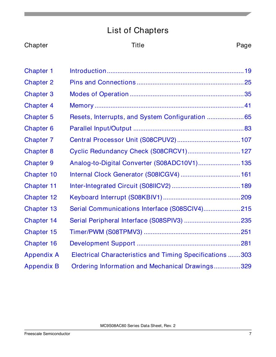
Chapter 1 Introduction
1.1 Overview
1.2 MCU Block Diagrams
1.3 System Clock Distribution
Chapter 2 Pins and Connections
2.1 Introduction
2.2 Device Pin Assignment
2.3 Recommended System Connections
2.3.1 Power (VDD, VSS, VDDAD, VSSAD)
2.3.2 Oscillator (XTAL, EXTAL)
2.3.3 RESET Pin
2.3.4 Background/Mode Select (BKGD/MS)
2.3.5 ADC Reference Pins (VREFH, VREFL)
2.3.6 External Interrupt Pin (IRQ)
2.3.7 General-Purpose I/O and Peripheral Ports
Chapter 3 Modes of Operation
3.1 Introduction
3.2 Features
3.3 Run Mode
3.4 Active Background Mode
3.5 Wait Mode
3.6 Stop Modes
3.6.1 Stop2 Mode
3.6.2 Stop3 Mode
3.6.3 Active BDM Enabled in Stop Mode
3.6.4 LVD Enabled in Stop Mode
3.6.5 On-Chip Peripheral Modules in Stop Modes
Chapter 4 Memory
4.1 MC9S08AC60 Series Memory Map
4.1.1 Reset and Interrupt Vector Assignments
4.2 Register Addresses and Bit Assignments
4.3 RAM
4.4 FLASH
4.4.1 Features
4.4.2 Program and Erase Times
4.4.3 Program and Erase Command Execution
4.4.4 Burst Program Execution
4.4.5 Access Errors
4.4.6 FLASH Block Protection
4.4.7 Vector Redirection
4.5 Security
4.6 FLASH Registers and Control Bits
4.6.1 FLASH Clock Divider Register (FCDIV)
4.6.2 FLASH Options Register (FOPT and NVOPT)
4.6.3 FLASH Configuration Register (FCNFG)
4.6.4 FLASH Protection Register (FPROT and NVPROT)
4.6.5 FLASH Status Register (FSTAT)
4.6.6 FLASH Command Register (FCMD)
Chapter 5 Resets, Interrupts, and System Configuration
5.1 Introduction
5.2 Features
5.3 MCU Reset
5.4 Computer Operating Properly (COP) Watchdog
5.5 Interrupts
5.5.1 Interrupt Stack Frame
5.5.2 External Interrupt Request (IRQ) Pin
5.5.2.1 Pin Configuration Options
5.5.2.2 Edge and Level Sensitivity
5.5.3 Interrupt Vectors, Sources, and Local Masks
5.6 Low-Voltage Detect (LVD) System
5.6.1 Power-On Reset Operation
5.6.2 LVD Reset Operation
5.6.3 LVD Interrupt Operation
5.6.4 Low-Voltage Warning (LVW)
5.7 Real-Time Interrupt (RTI)
5.8 MCLK Output
5.9 Reset, Interrupt, and System Control Registers and Control Bits
5.9.1 Interrupt Pin Request Status and Control Register (IRQSC)
5.9.2 System Reset Status Register (SRS)
5.9.3 System Background Debug Force Reset Register (SBDFR)
5.9.4 System Options Register (SOPT)
5.9.5 System MCLK Control Register (SMCLK)
5.9.6 System Device Identification Register (SDIDH, SDIDL)
5.9.7 System Real-Time Interrupt Status and Control Register (SRTISC)
5.9.8 System Power Management Status and Control 1 Register (SPMSC1)
5.9.9 System Power Management Status and Control 2 Register (SPMSC2)
5.9.10 System Options Register 2 (SOPT2)
Chapter 6 Parallel Input/Output
6.1 Introduction
6.2 Pin Descriptions
6.3 Parallel I/O Control
6.4 Pin Control
6.4.1 Internal Pullup Enable
6.4.2 Output Slew Rate Control Enable
6.4.3 Output Drive Strength Select
6.5 Pin Behavior in Stop Modes
6.6 Parallel I/O and Pin Control Registers
6.6.1 Port A I/O Registers (PTAD and PTADD)
6.6.2 Port A Pin Control Registers (PTAPE, PTASE, PTADS)
6.6.3 Port B I/O Registers (PTBD and PTBDD)
6.6.4 Port B Pin Control Registers (PTBPE, PTBSE, PTBDS)
6.6.5 Port C I/O Registers (PTCD and PTCDD)
6.6.6 Port C Pin Control Registers (PTCPE, PTCSE, PTCDS)
6.6.7 Port D I/O Registers (PTDD and PTDDD)
6.6.8 Port D Pin Control Registers (PTDPE, PTDSE, PTDDS)
6.6.9 Port E I/O Registers (PTED and PTEDD)
6.6.10 Port E Pin Control Registers (PTEPE, PTESE, PTEDS)
6.6.11 Port F I/O Registers (PTFD and PTFDD)
6.6.12 Port F Pin Control Registers (PTFPE, PTFSE, PTFDS)
6.6.13 Port G I/O Registers (PTGD and PTGDD)
6.6.14 Port G Pin Control Registers (PTGPE, PTGSE, PTGDS)
Chapter 7 Central Processor Unit (S08CPUV2)
7.1 Introduction
7.1.1 Features
7.2 Programmer’s Model and CPU Registers
7.2.1 Accumulator (A)
7.2.2 Index Register (H:X)
7.2.3 Stack Pointer (SP)
7.2.4 Program Counter (PC)
7.2.5 Condition Code Register (CCR)
7.3 Addressing Modes
7.3.1 Inherent Addressing Mode (INH)
7.3.2 Relative Addressing Mode (REL)
7.3.3 Immediate Addressing Mode (IMM)
7.3.4 Direct Addressing Mode (DIR)
7.3.5 Extended Addressing Mode (EXT)
7.3.6 Indexed Addressing Mode
7.3.6.1 Indexed, No Offset (IX)
7.3.6.2 Indexed, No Offset with Post Increment (IX+)
7.3.6.3 Indexed, 8-Bit Offset (IX1)
7.3.6.4 Indexed, 8-Bit Offset with Post Increment (IX1+)
7.3.6.5 Indexed, 16-Bit Offset (IX2)
7.3.6.6 SP-Relative, 8-Bit Offset (SP1)
7.3.6.7 SP-Relative, 16-Bit Offset (SP2)
7.4 Special Operations
7.4.1 Reset Sequence
7.4.2 Interrupt Sequence
7.4.3 Wait Mode Operation
7.4.4 Stop Mode Operation
7.4.5 BGND Instruction
7.5 HCS08 Instruction Set Summary
Chapter 8 Cyclic Redundancy Check (S08CRCV1)
8.1 Introduction
8.1.1 Features
8.1.2 Modes of Operation
8.1.3 Block Diagram
8.2 External Signal Description
8.3 Register Definition
8.3.1 Memory Map
8.3.2 Register Descriptions
8.3.2.1 CRC High Register (CRCH)
8.3.2.2 CRC Low Register (CRCL)
8.4 Functional Description
8.4.1 ITU-T (CCITT) Recommendations and Expected CRC Results
8.5 Initialization Information
Chapter 9 Analog-to-Digital Converter (S08ADC10V1)
9.1 Overview
9.2 Channel Assignments
9.2.1 Alternate Clock
9.2.2 Hardware Trigger
9.2.2.1 Analog Pin Enables
9.2.2.2 Low-Power Mode Operation
9.2.3 Temperature Sensor
9.2.4 Features
9.2.5 Block Diagram
9.3 External Signal Description
9.3.1 Analog Power (VDDAD)
9.3.2 Analog Ground (VSSAD)
9.3.3 Voltage Reference High (VREFH)
9.3.4 Voltage Reference Low (VREFL)
9.3.5 Analog Channel Inputs (ADx)
9.4 Register Definition
9.4.1 Status and Control Register 1 (ADCSC1)
9.4.2 Status and Control Register 2 (ADCSC2)
9.4.3 Data Result High Register (ADCRH)
9.4.4 Data Result Low Register (ADCRL)
9.4.5 Compare Value High Register (ADCCVH)
9.4.6 Compare Value Low Register (ADCCVL)
9.4.7 Configuration Register (ADCCFG)
9.4.8 Pin Control 1 Register (APCTL1)
9.4.9 Pin Control 2 Register (APCTL2)
9.5 Functional Description
9.5.1 Clock Select and Divide Control
9.5.2 Input Select and Pin Control
9.5.3 Hardware Trigger
9.5.4 Conversion Control
9.5.4.1 Initiating Conversions
9.5.4.2 Completing Conversions
9.5.4.3 Aborting Conversions
9.5.4.4 Power Control
9.5.4.5 Total Conversion Time
9.5.5 Automatic Compare Function
9.5.6 MCU Wait Mode Operation
9.5.7 MCU Stop3 Mode Operation
9.5.7.1 Stop3 Mode With ADACK Disabled
9.5.7.2 Stop3 Mode With ADACK Enabled
9.5.8 MCU Stop1 and Stop2 Mode Operation
9.6 Initialization Information
9.6.1 ADC Module Initialization Example
9.6.1.1 Initialization Sequence
9.6.1.2 Pseudo - Code Example
9.7 Application Information
9.7.1 External Pins and Routing
9.7.1.1 Analog Supply Pins
9.7.1.2 Analog Reference Pins
9.7.1.3 Analog Input Pins
9.7.2 Sources of Error
9.7.2.1 Sampling Error
9.7.2.2 Pin Leakage Error
9.7.2.3 Noise-Induced Errors
9.7.2.4 Code Width and Quantization Error
9.7.2.5 Linearity Errors
9.7.2.6 Code Jitter, Non-Monotonicity and Missing Codes
Chapter 10 Internal Clock Generator (S08ICGV4)
10.1 Introduction
10.2 Introduction
10.2.1 Features
10.2.2 Modes of Operation
10.2.3 Block Diagram
10.3 External Signal Description
10.3.1 EXTAL - External Reference Clock / Oscillator Input
10.3.2 XTAL - Oscillator Output
10.3.3 External Clock Connections
10.3.4 External Crystal/Resonator Connections
10.4 Register Definition
10.4.1 ICG Control Register 1 (ICGC1)
10.4.2 ICG Control Register 2 (ICGC2)
10.4.3 ICG Status Register 1 (ICGS1)
10.4.4 ICG Status Register 2 (ICGS2)
10.4.5 ICG Filter Registers (ICGFLTU, ICGFLTL)
10.4.6 ICG Trim Register (ICGTRM)
10.5 Functional Description
10.5.1 Off Mode (Off)
10.5.1.1 BDM Active
10.5.1.2 OSCSTEN Bit Set
10.5.1.3 Stop/Off Mode Recovery
10.5.2 Self-Clocked Mode (SCM)
10.5.3 FLL Engaged, Internal Clock (FEI) Mode
10.5.4 FLL Engaged Internal Unlocked
10.5.5 FLL Engaged Internal Locked
10.5.6 FLL Bypassed, External Clock (FBE) Mode
10.5.7 FLL Engaged, External Clock (FEE) Mode
10.5.7.1 FLL Engaged External Unlocked
10.5.7.2 FLL Engaged External Locked
10.5.8 FLL Lock and Loss-of-Lock Detection
10.5.9 FLL Loss-of-Clock Detection
10.5.10 Clock Mode Requirements
10.5.11 Fixed Frequency Clock
10.5.12 High Gain Oscillator
10.6 Initialization/Application Information
10.6.1 Introduction
10.6.2 Example #1: External Crystal = 32 kHz, Bus Frequency = 4.19 MHz
10.6.3 Example #2: External Crystal = 4 MHz, Bus Frequency = 20 MHz
10.6.4 Example #3: No External Crystal Connection, 5.4 MHz Bus Frequency
10.6.5 Example #4: Internal Clock Generator Trim
Chapter 11 Inter-Integrated Circuit (S08IICV2)
11.1 Introduction
11.2 External Signal Description
11.3 Register Definition
11.4 Functional Description
11.5 Resets
11.6 Interrupts
11.7 Initialization/Application Information
Chapter 12 Keyboard Interrupt (S08KBIV1)
12.1 Introduction
12.1.1 Features
12.1.2 KBI Block Diagram
12.2 Register Definition
12.2.1 KBI Status and Control Register (KBISC)
12.2.2 KBI Pin Enable Register (KBIPE)
12.3 Functional Description
12.3.1 Pin Enables
12.3.2 Edge and Level Sensitivity
12.3.3 KBI Interrupt Controls
Chapter 13 Serial Communications Interface (S08SCIV4)
13.1 Introduction
13.1.1 Features
13.1.2 Modes of Operation
13.1.3 Block Diagram
13.2 Register Definition
13.2.1 SCI Baud Rate Registers (SCIxBDH, SCIxBDL)
13.2.2 SCI Control Register 1 (SCIxC1)
13.2.3 SCI Control Register 2 (SCIxC2)
13.2.4 SCI Status Register 1 (SCIxS1)
13.2.5 SCI Status Register 2 (SCIxS2)
13.2.6 SCI Control Register 3 (SCIxC3)
13.2.7 SCI Data Register (SCIxD)
13.3 Functional Description
13.3.1 Baud Rate Generation
13.3.2 Transmitter Functional Description
13.3.2.1 Send Break and Queued Idle
13.3.3 Receiver Functional Description
13.3.3.1 Data Sampling Technique
13.3.3.2 Receiver Wakeup Operation
13.3.3.2.1 Idle-Line Wakeup
13.3.3.2.2 Address-Mark Wakeup
13.3.4 Interrupts and Status Flags
13.3.5 Additional SCI Functions
13.3.5.1 8- and 9-Bit Data Modes
13.3.5.2 Stop Mode Operation
13.3.5.3 Loop Mode
13.3.5.4 Single-Wire Operation
Chapter 14 Serial Peripheral Interface (S08SPIV3)
14.1 Introduction
14.1.1 Features
14.1.2 Block Diagrams
14.1.2.1 SPI System Block Diagram
14.1.2.2 SPI Module Block Diagram
14.1.3 SPI Baud Rate Generation
14.2 External Signal Description
14.2.1 SPSCK - SPI Serial Clock
14.2.2 MOSI - Master Data Out, Slave Data In
14.2.3 MISO - Master Data In, Slave Data Out
14.2.4 SS - Slave Select
14.3 Modes of Operation
14.3.1 SPI in Stop Modes
14.4 Register Definition
14.4.1 SPI Control Register 1 (SPIC1)
14.4.2 SPI Control Register 2 (SPIC2)
14.4.3 SPI Baud Rate Register (SPIBR)
14.4.4 SPI Status Register (SPIS)
14.4.5 SPI Data Register (SPID)
14.5 Functional Description
14.5.1 SPI Clock Formats
14.5.2 SPI Interrupts
14.5.3 Mode Fault Detection
Chapter 15 Timer/PWM (S08TPMV3)
15.1 Introduction
15.2 Features
15.3 TPMV3 Differences from Previous Versions
15.3.1 Migrating from TPMV1
15.3.2 Features
15.3.3 Modes of Operation
15.3.4 Block Diagram
15.4 Signal Description
15.4.1 Detailed Signal Descriptions
15.4.1.1 EXTCLK - External Clock Source
15.4.1.2 TPMxCHn - TPM Channel n I/O Pin(s)
15.5 Register Definition
15.5.1 TPM Status and Control Register (TPMxSC)
15.5.2 TPM-Counter Registers (TPMxCNTH:TPMxCNTL)
15.5.3 TPM Counter Modulo Registers (TPMxMODH:TPMxMODL)
15.5.4 TPM Channel n Status and Control Register (TPMxCnSC)
15.5.5 TPM Channel Value Registers (TPMxCnVH:TPMxCnVL)
15.6 Functional Description
15.6.1 Counter
15.6.1.1 Counter Clock Source
15.6.1.2 Counter Overflow and Modulo Reset
15.6.1.3 Counting Modes
15.6.1.4 Manual Counter Reset
15.6.2 Channel Mode Selection
15.6.2.1 Input Capture Mode
15.6.2.2 Output Compare Mode
15.6.2.3 Edge-Aligned PWM Mode
15.6.2.4 Center-Aligned PWM Mode
15.7 Reset Overview
15.7.1 General
15.7.2 Description of Reset Operation
15.8 Interrupts
15.8.1 General
15.8.2 Description of Interrupt Operation
15.8.2.1 Timer Overflow Interrupt (TOF) Description
15.8.2.1.1 Normal Case
15.8.2.1.2 Center-Aligned PWM Case
15.8.2.2 Channel Event Interrupt Description
15.8.2.2.1 Input Capture Events
15.8.2.2.2 Output Compare Events
15.8.2.2.3 PWM End-of-Duty-Cycle Events
15.9 The Differences from TPM v2 to TPM v3
Chapter 16 Development Support
16.1 Introduction
16.1.1 Features
16.2 Background Debug Controller (BDC)
16.2.1 BKGD Pin Description
16.2.2 Communication Details
16.2.3 BDC Commands
16.2.4 BDC Hardware Breakpoint
16.3 On-Chip Debug System (DBG)
16.3.1 Comparators A and B
16.3.2 Bus Capture Information and FIFO Operation
16.3.3 Change-of-Flow Information
16.3.4 Tag vs. Force Breakpoints and Triggers
16.3.5 Trigger Modes
16.3.6 Hardware Breakpoints
16.4 Register Definition
16.4.1 BDC Registers and Control Bits
16.4.1.1 BDC Status and Control Register (BDCSCR)
16.4.1.2 BDC Breakpoint Match Register (BDCBKPT)
16.4.2 System Background Debug Force Reset Register (SBDFR)
16.4.3 DBG Registers and Control Bits
16.4.3.1 Debug Comparator A High Register (DBGCAH)
16.4.3.2 Debug Comparator A Low Register (DBGCAL)
16.4.3.3 Debug Comparator B High Register (DBGCBH)
16.4.3.4 Debug Comparator B Low Register (DBGCBL)
16.4.3.5 Debug FIFO High Register (DBGFH)
16.4.3.6 Debug FIFO Low Register (DBGFL)
16.4.3.7 Debug Control Register (DBGC)
16.4.3.8 Debug Trigger Register (DBGT)
16.4.3.9 Debug Status Register (DBGS)
Appendix A Electrical Characteristics and Timing Specifications
A.1 Introduction
A.2 Parameter Classification
A.3 Absolute Maximum Ratings
A.4 Thermal Characteristics
A.5 ESD Protection and Latch-Up Immunity
A.6 DC Characteristics
A.7 Supply Current Characteristics
A.8 ADC Characteristics
A.9 Internal Clock Generation Module Characteristics
A.9.1 ICG Frequency Specifications
A.10 AC Characteristics
A.10.1 Control Timing
A.10.2 Timer/PWM (TPM) Module Timing
A.11 SPI Characteristics
A.12 FLASH Specifications
A.13 EMC Performance
A.13.1 Conducted Transient Susceptibility
Appendix B Ordering Information and Mechanical Drawings
B.1 Ordering Information
B.2 Orderable Part Numbering System
B.3 Mechanical Drawings




 2023年江西萍乡中考道德与法治真题及答案.doc
 2012年重庆南川中考生物真题及答案.doc
 2013年江西师范大学地理学综合及文艺理论基础考研真题.doc
 2020年四川甘孜小升初语文真题及答案I卷.doc
 2020年注册岩土工程师专业基础考试真题及答案.doc
 2023-2024学年福建省厦门市九年级上学期数学月考试题及答案.doc
 2021-2022学年辽宁省沈阳市大东区九年级上学期语文期末试题及答案.doc
 2022-2023学年北京东城区初三第一学期物理期末试卷及答案.doc
 2018上半年江西教师资格初中地理学科知识与教学能力真题及答案.doc
 2012年河北国家公务员申论考试真题及答案-省级.doc
 2020-2021学年江苏省扬州市江都区邵樊片九年级上学期数学第一次质量检测试题及答案.doc
 2022下半年黑龙江教师资格证中学综合素质真题及答案.doc