logo资料库

FEKO2017举例教程.pdf

第1页 / 共232页
第2页 / 共232页
第3页 / 共232页
第4页 / 共232页
第5页 / 共232页
第6页 / 共232页
第7页 / 共232页
第8页 / 共232页
资料共232页,剩余部分请下载后查看
FEKO 2017
Title page
Copyright
Contents
Introduction
A Antenna synthesis + analysis
A-1 Dipole example
A-2 Dipole in front of a cube
A-3 Dipole in front of a plate
A-4 Monopole antenna on a finite ground plane
A-5 Yagi-Uda antenna above a real ground
A-6 Pattern optimisation of a Yagi-Uda antenna
A-7 Log periodic antenna
A-8 Microstrip patch antenna
A-9 Proximity coupled patch antenna with microstrip feed
A-10 Modelling an aperture coupled patch antenna
A-11 Different ways to feed a horn antenna
A-12 Dielectric resonator antenna on finite ground
A-13 A lens antenna with ray launching geometrical optics (RL-GO)
A-14 Windscreen antenna on an automobile
A-15 Design of a MIMO elliptical ring antenna (characteristic modes)
A-16 Periodic boundary conditions for array analysis
A-17 Finite array with non-linear element spacing
B Antenna placement
B-1 Antenna coupling on an electrically large object
B-2 Antenna coupling using an ideal receiving antenna
B-3 Using a point source and ideal receiving antenna
C Radar cross section (RCS)
C-1 RCS of a thin dielectric sheet
C-2 RCS and near field of a dielectric sphere
C-3 Scattering width of an infinite cylinder
C-4 Periodic boundary conditions for FSS characterisation
D EMC analysis + cable coupling
D-1 Shielding factor of a sphere with finite conductivity
D-2 Calculating field coupling into a shielded cable
D-3 A magnetic-field probe
D-4 Antenna radiation hazard (RADHAZ) safety zones
E Waveguide + microwave circuits
E-1 Microstrip filter
E-2 S-parameter coupling in a stepped waveguide section
E-3 Using a non-radiating network to match a dipole antenna
E-4 Subdividing a model using non-radiating networks
E-5 Microstrip coupler
F Bio electromagnetics
F-1 Exposure of muscle tissue using MoM/FEM hybrid
F-2 Magnetic Resonance Imaging (MRI) birdcage head coil example
G Time domain examples
G-1 Time analysis of the effect of an incident plane wave on an obstacle
H Special solution methods
H-1 Forked dipole antenna (continuous frequency range)
H-2 Using the MLFMM for electrically large models
H-3 Horn feeding a large reflector
H-4 Optimise waveguide pin feed location
I User interface tools
I-1 Introduction to application automation
I-2 POSTFEKO application automation
I-3 Matching circuits generation with Optenni Lab
I-4 Using HyperStudy with FEKO to optimise a bandpass filter
J Index
Index

Learn moreataltairhyperworks.comExamplesGuideforFEKOv2017
Examples Guide 2017 RELEASE January 2017 Altair® HyperWorks® Version 2017 A Platform for Innovation®
Altair Engineering Support Contact Information Web site http://www.altairhyperworks.com http://www.altairhyperworks.com/ClientCenterHWSupportProduct.aspx http://www.altairhyperworks.com/feko Altair® HyperWorks® v. 2017 A Platform for Innovation™ Copyright c 1986–2016 Altair Engineering, Inc. All Rights Reserved. HyperWorks® 2017 products: HyperMesh® 1990–2016; HyperCrash® 2001–2016; OptiStruct® 1996–2016; RADIOSS® 1986– 2016; HyperView® 1999–2016; HyperView Player® 2001–2016; HyperMath® 2007-2016; HyperStudy® 1999–2016; HyperGraph® 1995–2016; MotionView® 1993–2016; MotionSolve® 2002–2016; HyperForm® 1998–2016; HyperXtrude® 1999–2016; Process Manager™ 2003– 2016; Templex™ 1990-2016; TextView™ 1996-2016; MediaView™ 1999-2016; TableView™ 2013- 2016; BatchMesher™ 2003–2016; HyperWeld® 2009–2016; HyperMold® 2009–2016; Manufac- turing Solutions™ 2005–2016; solidThinking Inspire® 2017 2009–2016; solidThinking Evolve® 2017 1993–2016; Durability Director™ 2009–2016; Suspension Director™ 2009–2016; AcuSolve® 1997–2016; AcuConsole® 2006–2016; SimLab® 2004–2016; Virtual Wind Tunnel™ 2012–2016; FEKO® ( c1999-2014 Altair Development S.A. (Pty) Ltd.; c2014-2016 Altair Engineering, Inc.); ConnectMe™ 2014–2016. Additional Altair Products: Multiscale Designer™ 2011–2016; Flux™ v.12.2 1983–2016; InCa3D v.3.1 1996–2016; CDE v.2 2012–2016; Got-It v.3 2002–2016; WinProp v.14 2000–2016 Altair Packaged Solution Offerings (PSOs) Copyright c 2008–2016 Automated Reporting Director™ 2008–2016; GeoMechanics Director 2011–2016; Impact Simu- lation Director™ 2010–2016; Model Mesher Director™ 2010–2016; Model Verification Director™ 2013–2016; NVH Director™ 2010–2016; Squeak and Rattle Director™ 2012–2016; Virtual Gauge Director™ 2012–2016; Weight Analytics™ 2013–2016; Weld Certification Director™ 2014–2016 Altair Simulation Cloud Suite: Simulation Manager™ 2003–2016; Compute Manager™ 2003–2016; Display Manager™ 2003– 2016; and Process Manager™ 2003–2016. Altair PBS Works™: Compute Manager™ 2012–2016; Display Manager™ 2013–2016; PBS™ 1994–2016; PBS Pro™ 1994–2016; PBS Professional® 1994–2016; PBS Application Services™ 2008–2016; PBS Analyt- ics™ 2008–2016; and PBS Desktop™ 2008–2012; e-Compute™ 2000–2010; OpenPBS® 1994– 2003 and Personal PBS® 2008–2012. Software products of solidThinking, Inc., a wholly owned subsidiary of Altair Engineer- ing: solidThinking Inspire® 2017 2009–2016; solidThinking Evolve®2017 1993–2016; solid- Thinking Compose™ 2017 2007–2016, solidThinking Activate™ 2017 1989–2016, solidThinking Embed™ 2017 1989–2016, solidThinking Embed™ SE 2017 1989–2016; Click2Extrude™ Metal 2017 1996–2016; Click2Extrude™ Polymer 2017 1996–2016; Click2Cast® 14.0 2011-2016; Click2Form™ 2017 1998–2016; Envision™ 2013–2016.
d Altair intellectual property rights are protected under U.S. and international laws and treaties. Additionally, Altair software is protected under patent #6,859,792 and other patents pending. All other marks are the property of their respective owners. ALTAIR ENGINEERING INC. Proprietary and Confidential. Contains Trade Secret Informa- tion. Not for use or disclosure outside of Altair and its licensed clients. Information contained in Altair software shall not be decompiled, disassembled, “unlocked”, reverse translated, reverse engi- neered, or publicly displayed or publicly performed in any manner. Usage of the software is only as explicitly permitted in the end user software license agreement. Copyright notice does not imply publication. Third party software licenses AcuConsole contains material licensed from Intelligent Light (www.ilight.com) and used by per- mission. Software Security Measures: Altair Engineering Inc. and its subsidiaries and affiliates reserve the right to embed software security mechanisms in the Software for the purpose of detecting the installation and/or use of illegal copies of the Software. The Software may collect and transmit non-proprietary data about those illegal copies. Data collected will not include any customer data created by or used in connection with the Software and will not be provided to any third party, except as may be required by law or legal process or to enforce our rights with respect to the use of any illegal copies of the Software. By using the Software, each user consents to such detection and collection of data, as well as its transmission and use if an illegal copy of the Software is detected. No steps may be taken to avoid or detect the purpose of any such security mechanisms. January 2017 FEKO Examples Guide
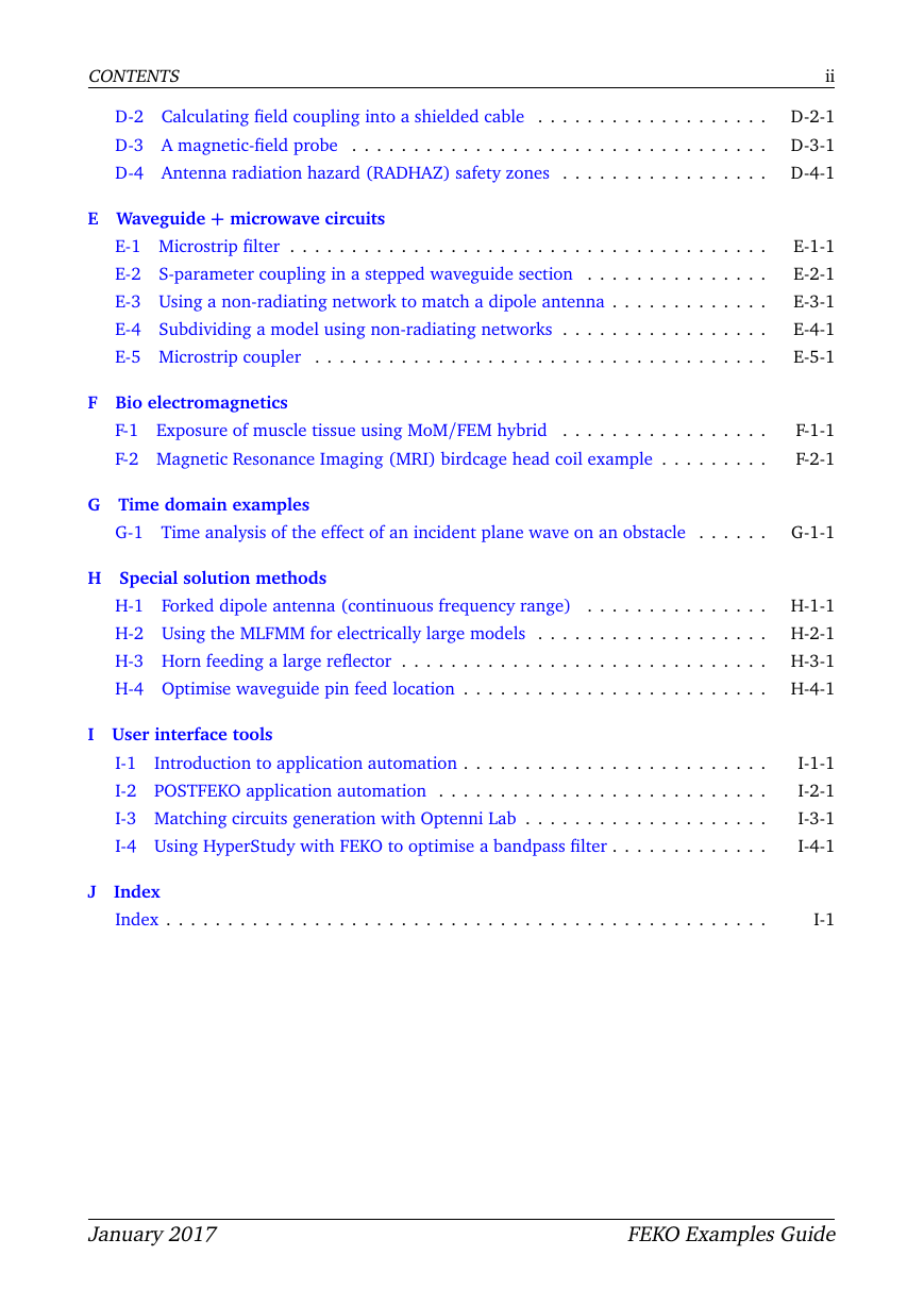
CONTENTS i Contents Introduction . . . . . . . . . . . . . . . . . . . . . . . . . . . . . . . . . . . . . . . . . . . . 1 A Antenna synthesis + analysis A-1-1 A-1 Dipole example . . . . . . . . . . . . . . . . . . . . . . . . . . . . . . . . . . . . . . . A-2-1 A-2 Dipole in front of a cube . . . . . . . . . . . . . . . . . . . . . . . . . . . . . . . . . A-3-1 A-3 Dipole in front of a plate . . . . . . . . . . . . . . . . . . . . . . . . . . . . . . . . . A-4-1 A-4 Monopole antenna on a finite ground plane . . . . . . . . . . . . . . . . . . . . . A-5-1 A-5 Yagi-Uda antenna above a real ground . . . . . . . . . . . . . . . . . . . . . . . . . A-6-1 A-6 Pattern optimisation of a Yagi-Uda antenna . . . . . . . . . . . . . . . . . . . . . . A-7-1 A-7 Log periodic antenna . . . . . . . . . . . . . . . . . . . . . . . . . . . . . . . . . . . A-8-1 A-8 Microstrip patch antenna . . . . . . . . . . . . . . . . . . . . . . . . . . . . . . . . . A-9 Proximity coupled patch antenna with microstrip feed . . . . . . . . . . . . . . . A-9-1 A-10 Modelling an aperture coupled patch antenna . . . . . . . . . . . . . . . . . . . A-10-1 A-11 Different ways to feed a horn antenna . . . . . . . . . . . . . . . . . . . . . . . . A-11-1 A-12 Dielectric resonator antenna on finite ground . . . . . . . . . . . . . . . . . . . . A-12-1 A-13 A lens antenna with ray launching geometrical optics (RL-GO) . . . . . . . . . A-13-1 A-14 Windscreen antenna on an automobile . . . . . . . . . . . . . . . . . . . . . . . . A-14-1 A-15 Design of a MIMO elliptical ring antenna (characteristic modes) . . . . . . . . A-15-1 A-16 Periodic boundary conditions for array analysis . . . . . . . . . . . . . . . . . . A-16-1 A-17 Finite array with non-linear element spacing . . . . . . . . . . . . . . . . . . . . A-17-1 B Antenna placement B-1 Antenna coupling on an electrically large object . . . . . . . . . . . . . . . . . . . B-2 Antenna coupling using an ideal receiving antenna . . . . . . . . . . . . . . . . . B-3 Using a point source and ideal receiving antenna . . . . . . . . . . . . . . . . . . B-1-1 B-2-1 B-3-1 C Radar cross section (RCS) C-1 RCS of a thin dielectric sheet . . . . . . . . . . . . . . . . . . . . . . . . . . . . . . . C-2 RCS and near field of a dielectric sphere . . . . . . . . . . . . . . . . . . . . . . . C-3 Scattering width of an infinite cylinder . . . . . . . . . . . . . . . . . . . . . . . . C-4 Periodic boundary conditions for FSS characterisation . . . . . . . . . . . . . . . C-1-1 C-2-1 C-3-1 C-4-1 D EMC analysis + cable coupling D-1 Shielding factor of a sphere with finite conductivity . . . . . . . . . . . . . . . . D-1-1 January 2017 FEKO Examples Guide
CONTENTS D-2 Calculating field coupling into a shielded cable . . . . . . . . . . . . . . . . . . . D-3 A magnetic-field probe . . . . . . . . . . . . . . . . . . . . . . . . . . . . . . . . . . D-4 Antenna radiation hazard (RADHAZ) safety zones . . . . . . . . . . . . . . . . . E Waveguide + microwave circuits E-1 Microstrip filter . . . . . . . . . . . . . . . . . . . . . . . . . . . . . . . . . . . . . . . E-2 S-parameter coupling in a stepped waveguide section . . . . . . . . . . . . . . . E-3 Using a non-radiating network to match a dipole antenna . . . . . . . . . . . . . E-4 Subdividing a model using non-radiating networks . . . . . . . . . . . . . . . . . E-5 Microstrip coupler . . . . . . . . . . . . . . . . . . . . . . . . . . . . . . . . . . . . . ii D-2-1 D-3-1 D-4-1 E-1-1 E-2-1 E-3-1 E-4-1 E-5-1 F Bio electromagnetics F-1 Exposure of muscle tissue using MoM/FEM hybrid . . . . . . . . . . . . . . . . . F-2 Magnetic Resonance Imaging (MRI) birdcage head coil example . . . . . . . . . F-1-1 F-2-1 G Time domain examples G-1 Time analysis of the effect of an incident plane wave on an obstacle . . . . . . G-1-1 H Special solution methods H-1 Forked dipole antenna (continuous frequency range) . . . . . . . . . . . . . . . H-1-1 H-2 Using the MLFMM for electrically large models . . . . . . . . . . . . . . . . . . . H-2-1 H-3 Horn feeding a large reflector . . . . . . . . . . . . . . . . . . . . . . . . . . . . . . H-3-1 H-4 Optimise waveguide pin feed location . . . . . . . . . . . . . . . . . . . . . . . . . H-4-1 I User interface tools I-1 Introduction to application automation . . . . . . . . . . . . . . . . . . . . . . . . . I-2 POSTFEKO application automation . . . . . . . . . . . . . . . . . . . . . . . . . . . I-3 Matching circuits generation with Optenni Lab . . . . . . . . . . . . . . . . . . . . I-4 Using HyperStudy with FEKO to optimise a bandpass filter . . . . . . . . . . . . . J Index Index . . . . . . . . . . . . . . . . . . . . . . . . . . . . . . . . . . . . . . . . . . . . . . . . . I-1-1 I-2-1 I-3-1 I-4-1 I-1 January 2017 FEKO Examples Guide
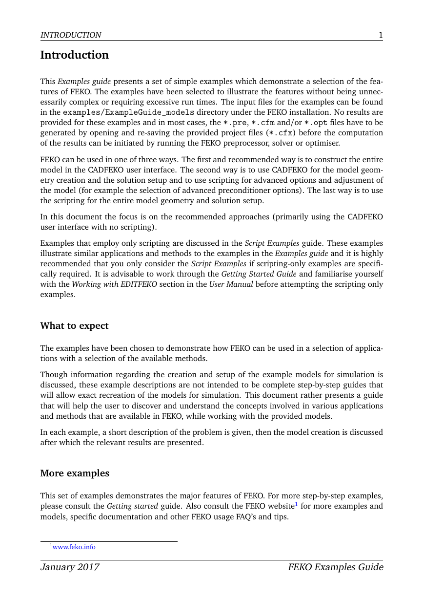
INTRODUCTION Introduction 1 This Examples guide presents a set of simple examples which demonstrate a selection of the fea- tures of FEKO. The examples have been selected to illustrate the features without being unnec- essarily complex or requiring excessive run times. The input files for the examples can be found in the examples/ExampleGuide_models directory under the FEKO installation. No results are provided for these examples and in most cases, the *.pre, *.cfm and/or *.opt files have to be generated by opening and re-saving the provided project files (*.cfx) before the computation of the results can be initiated by running the FEKO preprocessor, solver or optimiser. FEKO can be used in one of three ways. The first and recommended way is to construct the entire model in the CADFEKO user interface. The second way is to use CADFEKO for the model geom- etry creation and the solution setup and to use scripting for advanced options and adjustment of the model (for example the selection of advanced preconditioner options). The last way is to use the scripting for the entire model geometry and solution setup. In this document the focus is on the recommended approaches (primarily using the CADFEKO user interface with no scripting). Examples that employ only scripting are discussed in the Script Examples guide. These examples illustrate similar applications and methods to the examples in the Examples guide and it is highly recommended that you only consider the Script Examples if scripting-only examples are specifi- cally required. It is advisable to work through the Getting Started Guide and familiarise yourself with the Working with EDITFEKO section in the User Manual before attempting the scripting only examples. What to expect The examples have been chosen to demonstrate how FEKO can be used in a selection of applica- tions with a selection of the available methods. Though information regarding the creation and setup of the example models for simulation is discussed, these example descriptions are not intended to be complete step-by-step guides that will allow exact recreation of the models for simulation. This document rather presents a guide that will help the user to discover and understand the concepts involved in various applications and methods that are available in FEKO, while working with the provided models. In each example, a short description of the problem is given, then the model creation is discussed after which the relevant results are presented. More examples This set of examples demonstrates the major features of FEKO. For more step-by-step examples, please consult the Getting started guide. Also consult the FEKO website1 for more examples and models, specific documentation and other FEKO usage FAQ’s and tips. 1www.feko.info January 2017 FEKO Examples Guide
Chapter A Antenna synthesis + analysis
分享到:
收藏