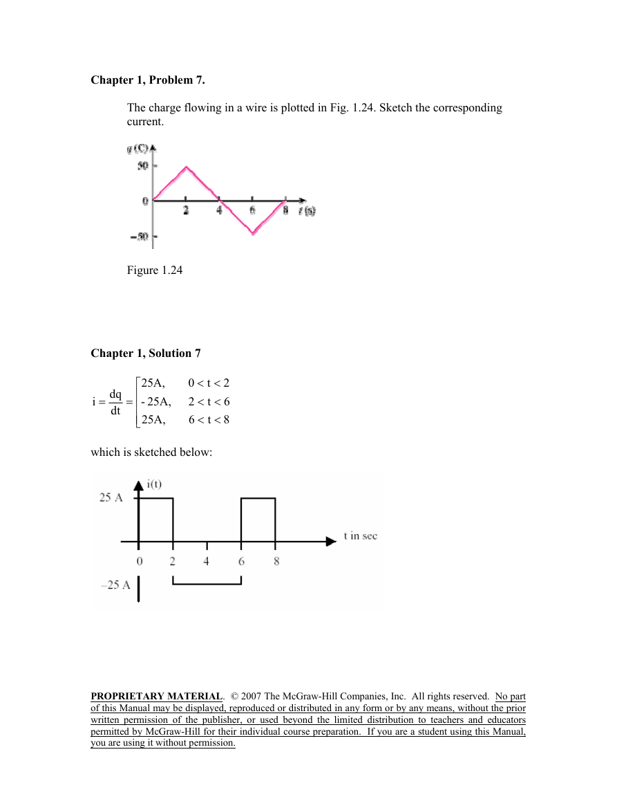
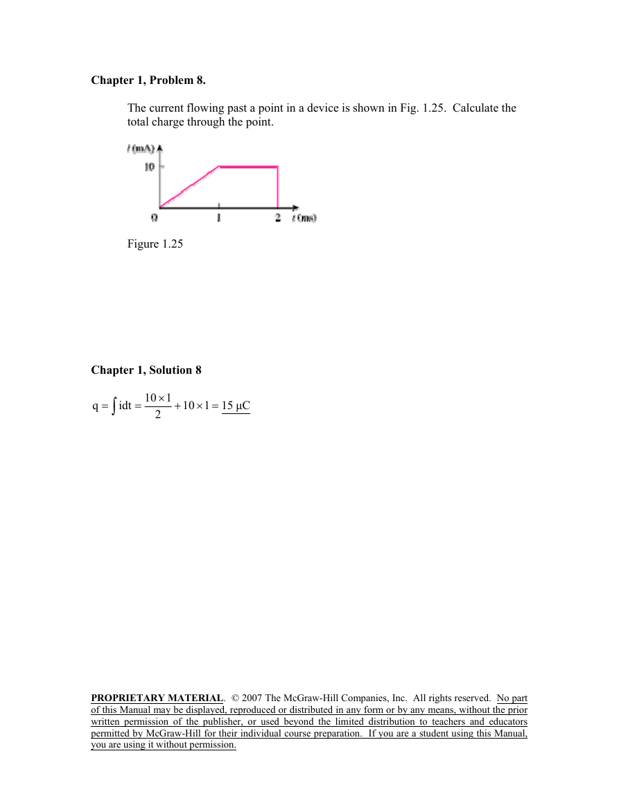
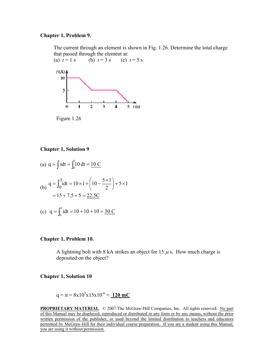
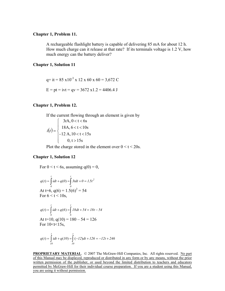
Chapter 1, Solution 4
Chapter 1, Solution 5
Chapter 1, Solution 13
Chapter 1, Solution 16
Chapter 1, Solution 17
Chapter 1, Solution 18
Chapter 1, Solution 19
Chapter 1, Solution 20
Chapter 1, Solution 21
Chapter 1, Solution 22
Chapter 1, Solution 23
Chapter 1, Solution 24
Chapter 1, Solution 25
Chapter 1, Solution 26
Chapter 1, Solution 27
Chapter 1, Solution 28
Chapter 1, Solution 29
Chapter 1, Solution 30
Chapter 1, Solution 32
Chapter 1, Solution 33
Chapter 1, Solution 35
Chapter 1, Solution 36
Chapter 1, Solution 37
Chapter 1, Solution 38
Chapter 1, Solution 39
Chapter 2, Solution 1
Chapter 2, Solution 2
Chapter 2, Solution 3
Chapter 2, Solution 4
Chapter 2, Solution 5
Chapter 2, Solution 6
Chapter 2, Solution 7
Chapter 2, Solution 8
Chapter 2, Solution 9
Chapter 2, Solution 10
Chapter 2, Solution 11
Chapter 2, Solution 15
Chapter 2, Solution 16
Chapter 2, Solution 17
Chapter 2, Solution 18
APPLYING KVL,
Chapter 2, Solution 19
APPLYING KVL AROUND THE LOOP, WE OBTAIN
Chapter 2, Solution 20
APPLYING KVL AROUND THE LOOP,
Chapter 2, Solution 21
Chapter 2, Solution 22
Chapter 2, Solution 26
Chapter 2, Solution 27
Chapter 2, Solution 29
Chapter 2, Solution 30
Chapter 2, Solution 31
8 ( 10(
Chapter 2, Solution 34
I 24 ( 50(
Chapter 2, Solution 36
Chapter 2, Solution 37
Chapter 2, Solution 38
Chapter 2, Solution 39
REQ = 5(
Chapter 2, Solution 46
(A) RA =
(A) R1 =
R1 = 18(, R2 = 6(, R3 = 3(
Chapter 2, Solution 52
Chapter 2, Solution 55
We convert the T to .
Chapter 2, Solution 56
Chapter 2, Solution 57
Chapter 2, Solution 58
Chapter 2, Solution 59
TOTAL POWER P = 30 + 40 + 50 + 120 W = VI
OR I = P/(V) = 120/(100) = 1.2 A
Chapter 2, Solution 63
Chapter 2, Solution 65
4 K(
Chapter 2, Solution 66
Chapter 2, Solution 68
(F)
Chapter 2, Solution 69
Chapter 2, Solution 71
Chapter 2, Solution 72
Chapter 2, Solution 74
Chapter 2, Solution 75
Chapter 2, Solution 76
Chapter 2, Solution 77
Chapter 2, Solution 78
Chapter 2, Solution 79
Chapter 2, Solution 80
Chapter 2, Solution 82
Chapter 2, Solution 83
Chapter 3, Solution 1
At node 1,
Applying KCL to the upper node,
Figure 3.53
Chapter 3, Solution 5
Apply KCL to the top node.
Chapter 3, Solution 6
i1 + i2 + i3 = 0
Chapter 3, Solution 7
Chapter 3, Solution 8
Chapter 3, Solution 9
Chapter 3, Solution 10
At the non-reference node,
Chapter 3, Solution 11
Chapter 3, Solution 12
Chapter 3, Solution 13
At node number 2, [(v2 + 2) – 0]/10 + v2/4 = 3 or v2 = 8 volts
Chapter 3, Solution 14
Chapter 3, Solution 15
Chapter 3, Solution 16
Chapter 3, Solution 17
Chapter 3, Solution 18
Chapter 3, Solution 24
Chapter 3, Solution 25
Chapter 3, Solution 27
At node 1,
Chapter 3, Solution 30
Chapter 3, Solution 31
Chapter 3, Solution 32
Chapter 3, Solution 33
Chapter 3, Solution 35
Chapter 3, Solution 36
or
i1 = -I1 = -9/11 = -0.8181 A, i2 = I1 – I2 = 10/11 = 1.4545 A.
vo = 6i2 = 6x1.4545 = 8.727 V.
Chapter 3, Solution 37
Chapter 3, Solution 40
Chapter 3, Solution 41
Chapter 3, Solution 43
Chapter 3, Solution 44
Chapter 3, Solution 45
Chapter 3, Solution 49
Chapter 3, Solution 50
Chapter 3, Solution 51
Chapter 3, Solution 53
Chapter 3, Solution 55
Chapter 3, Solution 56
Chapter 3, Solution 58
Chapter 3, Solution 59
Chapter 3, Solution 60
Chapter 3, Solution 61
Chapter 3, Solution 62
Chapter 3, Solution 63
Chapter 3, Solution 64
Chapter 3, Solution 66
Chapter 3, Solution 67
V3
Chapter 3, Solution 68
V1 Vo
Chapter 3, Solution 70
Chapter 3, Solution 71
Chapter 3, Solution 72
Chapter 3, Solution 73
Chapter 3, Solution 74
Chapter 3, Solution 75
Chapter 3, Solution 76
Chapter 3, Solution 77
Chapter 3, Solution 80
Chapter 3, Solution 81
Chapter 3, Solution 82
Chapter 3, Solution 83
The circuit is shown below.
When the circuit is saved and simulated, we obtain v2 = –12.5 volts
Chapter 3, Solution 84
Chapter 3, Solution 86
Chapter 3, Solution 87
Chapter 3, Solution 88
Chapter 3, Solution 89
Chapter 3, Solution 90
Chapter 3, Problem 93
Chapter 3, Solution 93
Chapter 4, Solution 6.
Chapter 4, Solution 7.
Chapter 4, Solution 8.
Chapter 4, Solution 9.
vb
Figure 4.81 For Prob. 4.13.
Chapter 4, Solution 13.
Let vo = vo1 + vo2 + vo3, where vo1, vo2 , and vo3, are due to the 20-V, 1-A, and 2-A sources respectively. For vo1, consider the circuit below.
Let i = i1 + i2 + i3, where i1 , i2 , and i3 are due to the 20-V, 2-A, and 16-V sources. For i1, consider the circuit below.
Chapter 4, Solution 18.
Chapter 4, Solution 20.
Chapter 4, Solution 24.
Chapter 4, Solution 26.
Chapter 4, Solution 28.
Chapter 4, Solution 39.
Chapter 4, Solution 40.
Chapter 4, Solution 46.
Chapter 4, Solution 56.
This problem does not have a solution as it was originally stated. The reason for this is that the load resistor is in series with a current source which means that the only equivalent circuit that will work will be a Norton circuit where the value of RN = infinity. IN can be found by solving for Isc.
RTh = (10 + 20)||(50 + 40) 30||90 = 22.5 ohms
We need to first find RTh and VTh.
Chapter 5, Solution 1.
(a) Rin = 1.5 M(
Chapter 5, Problem 2
Example 5.1
Chapter 5, Problem 7
At node 2, (V1 – V0)/100 k = (V0 – (–AVd))/100
Chapter 5, Problem 8
Chapter 5, Problem 9
Chapter 5, Problem 10
Chapter 5, Problem 11
Chapter 5, Solution 11.
Chapter 5, Solution 12.
Chapter 5, Problem 13
Chapter 5, Solution 13.
Chapter 5, Problem 15
Chapter 5, Problem 16
Chapter 5, Problem 17
Chapter 5, Solution 18.
Chapter 5, Problem 19
Chapter 5, Problem 20
Chapter 5, Solution 21.
Chapter 5, Problem 22
Chapter 5, Solution 22.
Chapter 5, Problem 23
Chapter 5, Problem 24
Chapter 5, Solution 25.
Chapter 5, Problem 26
–
Chapter 5, Solution 27.
Chapter 5, Problem 28
Chapter 5, Solution 28.
Chapter 5, Problem 29
Chapter 5, Problem 30
Chapter 5, Problem 31
Chapter 5, Problem 32
Chapter 5, Problem 33
Chapter 5, Problem 35
Chapter 5, Problem 36
Chapter 5, Problem 37
Chapter 5, Solution 37.
Chapter 5, Problem 38
Chapter 5, Solution 38.
Chapter 5, Problem 39
Chapter 5, Problem 41
Chapter 5, Solution 41.
Chapter 5, Problem 42
Chapter 5, Problem 43
Chapter 5, Problem 44
Chapter 5, Problem 45
Chapter 5, Problem 46
Chapter 5, Solution 47.
Chapter 5, Problem 48
Chapter 5, Problem 49
Chapter 5, Problem 50
Chapter 5, Problem 51
Chapter 5, Solution 51.
We achieve this by cascading an inverting amplifier and two-input inverting summer as shown below:
Chapter 5, Problem 52
Chapter 5, Problem 53
Chapter 5, Solution 53.
(a)
Chapter 5, Problem 55
Chapter 5, Solution 55.
Let A1 = k, A2 = k, and A3 = k/(4)
Chapter 5, Solution 56.
50 k( 100 k(
50 k(
vs2
Chapter 5, Solution 57.
Chapter 5, Problem 58
Chapter 5, Solution 60.
Chapter 5, Problem 62
Chapter 5, Problem 63
Chapter 5, Problem 64
Chapter 5, Problem 65
Chapter 5, Problem 66
Chapter 5, Problem 67
Chapter 5, Problem 70
Chapter 5, Problem 71
Chapter 5, Problem 72
Chapter 5, Problem 73
Chapter 5, Problem 74
Chapter 5, Problem 75
Chapter 5, Problem 76
Chapter 5, Solution 76.
The schematic is shown below. IPROBE is inserted to measure io. Upon simulation, the value of io is displayed on IPROBE as
Chapter 5, Problem 77
Chapter 5, Solution 77.
The schematic for the PSpice solution is shown below.
Note that the output voltage, –3.343 mV, agrees with the answer to problem, 5.48.
Chapter 5, Problem 78
Chapter 5, Problem 79
Chapter 5, Problem 81
Chapter 5, Problem 82
Chapter 5, Problem 83
Chapter 5, Problem 84
Chapter 5, Solution 85.
Chapter 5, Problem 86
Chapter 5, Problem 87
Chapter 5, Problem 88
Chapter 5, Solution 88.
We need to find VTh at terminals a – b, from this,
Chapter 5, Problem 90
Chapter 5, Problem 91
Chapter 5, Problem 92
Chapter 5, Problem 93
Chapter 6, Solution 2.
–10
Chapter 6, Solution 5.
Chapter 6, Solution 11.
Chapter 6, Solution 12.
Chapter 6, Solution 14.
Ceq
Chapter 6, Solution 18.
b
Chapter 6, Solution 20.
20(F is series with 80(F = 20x80/(100) = 16(F
14(F is parallel with 16(F = 30(F
i = ,
Chapter 6, Solution 27.
Chapter 6, Solution 35.
Chapter 6, Solution 36.
Chapter 6, Solution 44.
Under dc conditions, the circuit is equivalent to that shown below:
Chapter 6, Solution 48.
Chapter 6, Solution 49.
Chapter 6, Solution 50.
Chapter 6, Solution 52.
Leq
Chapter 6, Solution 61.
(a) 40 J
Chapter 6, Solution 66.
The output of the first op amp is
dt =
Consider the op amp as shown below:
showing that the circuit is a noninverting integrator.
RC = 0.01 x 20 x 10-3 sec
-30 mV
From the given circuit,
Since two 10(F capacitors in series gives 5(F, rated at 600V, it requires 8 groups in parallel with each group consisting of two capacitors in series, as shown below:
Chapter 6, Solution 84.
Chapter 6, Solution 86.
Chapter 1, Solution 4
Chapter 1, Solution 5


 2023年江西萍乡中考道德与法治真题及答案.doc
 2012年重庆南川中考生物真题及答案.doc
 2013年江西师范大学地理学综合及文艺理论基础考研真题.doc
 2020年四川甘孜小升初语文真题及答案I卷.doc
 2020年注册岩土工程师专业基础考试真题及答案.doc
 2023-2024学年福建省厦门市九年级上学期数学月考试题及答案.doc
 2021-2022学年辽宁省沈阳市大东区九年级上学期语文期末试题及答案.doc
 2022-2023学年北京东城区初三第一学期物理期末试卷及答案.doc
 2018上半年江西教师资格初中地理学科知识与教学能力真题及答案.doc
 2012年河北国家公务员申论考试真题及答案-省级.doc
 2020-2021学年江苏省扬州市江都区邵樊片九年级上学期数学第一次质量检测试题及答案.doc
 2022下半年黑龙江教师资格证中学综合素质真题及答案.doc