soiseek搜iC世界首个完全基于中文的IC专业搜索引擎。立即访问Soiseek 搜索中文Datasheet!IC搜索手气不错上 www.soiseek.cn 看中文版IC手册!小提示:使用空格同时搜索多个关键词。尝试“atmel 8 bit 微控制器”。世界首个全中文IC搜索引擎IC型号大全 - 关于Soiseek - 发送反馈把Soiseek设为首页版权声明:Soiseek所提供的所有IC数据手册(Datasheet)的中文译本,仅供参考,所有版权归发布厂商所有。对于可能出现的翻译错误,Soiseek恕不负责。请用户以原版数据手册内容为准。Soiseek免费提供下载的IC数据手册(Datasheet)的PDF来自于发布厂商,所有版权归发布厂商所有。Soiseek不对数据手册(Datasheet)中内容的真实性和准确性负责。欢迎提出建议,指正错误与疏漏。我们永远致力于为您提供更好的搜索结果。联系我们:http://www.soiseek.cn/tellus �
Soiseek.cn看中文数据手册
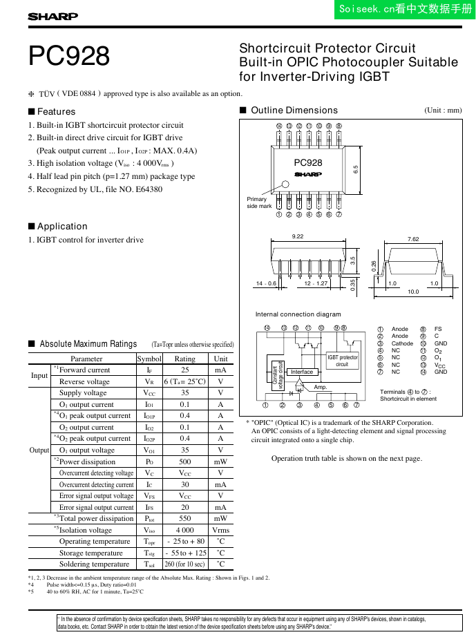
FeaturesOutline Dimensions(Unit : mm)(Ta=Topr unless otherwise specified)Operation truth table is shown on the next page.PC928PC928PC9286.512345678910111213149.227.621.01.010.00.353.50.26Amp.Constant voltage circuitIGBT protectorcircuitInterface8910111213141234567Internal connection diagram1Anode2Anode4NC5NC6NC7NC8FS9C10GND11O212O113VCC14GNDTerminals 4 to 7 : Shortcircuit in element3CathodeShortcircuit Protector Circuit Built-in OPIC Photocoupler Suitable for Inverter-Driving IGBTAbsolute Maximum RatingsRatingInput*1Forward currentIF25mAReverse voltageVRVOutputSupply voltageVCC35V0.1A*4IO1P0.4A0.1A*40.4A35V*2Power dissipationPO500mWOvercurrent detecting voltageVCVCCVOvercurrent detecting currentIC30mAError signal output voltageVFSVCCVError signal output currentIFS20mA*3Total power dissipationPtot550mW*5Isolation voltageVisoVrmsOperating temperatureTopr-25to +80˚CStorage temperatureTstg-55to +125˚CSoldering temperatureTsol260 (for 10 sec)˚CPrimary side markIO1IO2IO2P4 0001. IGBT control for inverter driveSymbolUnitParameter1. Built-in IGBT shortcircuit protector circuit2. Built-in direct drive circuit for IGBT drive (Peak output current ... I , I : MAX. 0.4A)O1PO2P3. High isolation voltage (V : 4 000V )isorms5. Recognized by UL, file NO. E643804. Half lead pin pitch (p=1.27 mm) package typeApplicationVO1O1 output currentO1 output voltageO2 output currentO2 peak output currentO1 peak output current6 (Ta=25˚C)14-0.612-1.27*4Pulse width<=0.15ms, Duty ratio=0.01*540 to 60% RH, AC for 1 minute, Ta=25˚C*1, 2, 3 Decrease in the ambient temperature range of the Absolute Max. Rating : Shown in Figs. 1 and 2.* "OPIC" (Optical IC) is a trademark of the SHARP Corporation. An OPIC consists of a light-detecting element and signal processing circuit integrated onto a single chip.nnnn data books, etc. Contact SHARP in order to obtain the latest version of the device specification sheets before using any SHARP's device.”“In the absence of confirmation by device specification sheets, SHARP takes no responsibility for any defects that occur in equipment using any of SHARP's devices, shown in catalogs,h TÜV(VDE 0884) approved type is also available as an option.�
Soiseek.cn看中文数据手册
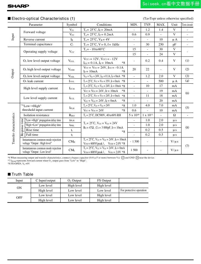
(Ta=Topr unless otherwise specified)Electro-optical Characteristics (1)Truth TablePC928ONLow levelHigh levelHigh levelHigh levelLow levelLow levelFor protective operationOFFLow levelLow levelHigh levelHigh levelLow levelHigh levelMIN.TYP.MAX.Test circuitForward voltageVF1Ta=25˚C, IF=20mA-1.21.4V-VF2Ta=25˚C, IF=0.2mA0.60.9-V-Reverse currentIRTa=25˚C, VR=4V--10mA-Terminal capacitanceCtTa=25˚C, V=0, f=1kHz-30250pF-Operating supply voltageVCCTa= -10to60˚C15-30V--15-24V*8IO1=0.1A, IF=10mA-0.20.4V(1)*8VCC=VO1=24V, IO2= -0.1AIF=10mA2022-V(2)*8-1.22.0(3)Ta=25˚C, VCC=VO1=35V, IF=0mA*8--500(4)High level supply currentICCH*8Ta=25˚C, VCC=VO1=24V, IF=10mA-1017mA(6)*8VCC=VO1=24V, IF=10mA--19mALow level supply currentICCLTa=25˚C, VCC=VO1=24V, IF=0mA*8-1118mAVCC=VO1=24V, IF=0mA*8--20mAIFLHTa=25˚C, VCC=VO1=24V*81.04.07.0mA(5)VCC=VO1=24V*80.6-10mAIsolation resistanceRISO5x1010--WResponse time"LowfiHigh" propagation delay timetPLHTa=25˚C, VCC=VO1=24V*8-1.02.0ms(8)"HighfiLow" propagation delay timetPHL-1.02.0msRise timetr-0.20.5msFall timetf-0.20.5msInstantaneous common mode rejection voltage "Output : High level"CMHVCM=600V(peak),DVO2H=2.0V*8Ta=25˚C, VCC=VO1=24V, IF=10mA--V/ms(7)Instantaneous common mode rejection voltage "Output : Low level"CMLTa=25˚C, VCC=VO1=24V, IF=0mAVCM=600V(peak),DVO2L=2.0V*8--V/ms*7"LowfiHigh" threshold input currentO2 OutputFS OutputC Input/outputParameterSymbolConditionsUnitVmA1x1011-1 5001 500VO1LVO2HVO2LIO1LVCC=VO1=24V, IO2=0.1A, IF=0mARG=47W, CG=3 000pF, IF=10mATa=25˚C, DC500V, 40to60%RHVCC1=12V, VCC2= -12VO1 low level output voltageO2 high level output voltageO2 low level output voltageO1 leak current*6 When measuring output and transfer characteristics, connect a bypass capacitor (0.01mF or more) between Vcc and GND near the device. *7 I represents forward current when O output goes from "Low" to "High".FLH2*8 FS=OPEN, V =0VCInputOutputTransfer characteristicsInputnn1314�
Soiseek.cn看中文数据手册
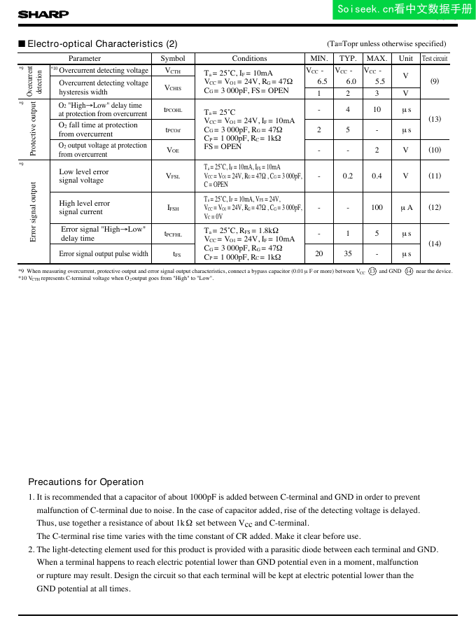
(Ta=Topr unless otherwise specified)Electro-optical Characteristics (2)PC928MIN.TYP.MAX.Test circuitOvercurrent detecting voltage*10VCTHTa=25˚C, IF=10mA6.56.05.5V(9)Overcurrent detecting voltage hysteresis widthVCHIS123VProtective outputOvercurrentdetectiontPCOHLTa=25˚CFS=OPEN-410ms(13)tPCOtf25-ms--2V(10)VOELow level error signal voltageVFSLTa=25˚C, IF=10mA, IFS=10mAC=OPEN-0.20.4V(11)High level error signal currentIFSHVC=0V--100mA(12)tPCFHLTa=25˚C, RFS=1.8kWVCC=VO1=24V, IF=10mA-15ms(14)Error signal output pulse widthDtFS2035-ms*9*9*9VCC-VCC-VCC-VCC=VO1=24V, RG=47WVCC=VO1=24V, IF=10mACG=3 000pF, RG=47WCP=1 000pF, RC=1kWVCC=VO1=24V, RG=47W, CG=3 000pF, VCC=VO1=24V, RG=47W, CG=3 000pF, Ta=25˚C, IF=10mA, VFS=24V,CG=3 000pF, RG=47WCP=1 000pF, RC=1kWPrecautions for OperationParameterSymbolConditionsUnitCG=3 000pF, FS=OPENO2 "HighfiLow" delay time at protection from overcurrentO2 fall time at protection from overcurrentO2 output voltage at protection from overcurrentError signal output*10 V represents C-terminal voltage when O output goes from "High" to "Low".CTH2*9 When measuring overcurrent, protective output and error signal output characteristics, connect a bypass capacitor (0.01mF or more) between V and GNDCC1. It is recommended that a capacitor of about 1000pF is added between C-terminal and GND in order to prevent malfunction of C-terminal due to noise. In the case of capacitor added, rise of the detecting voltage is delayed. Thus, use together a resistance of about 1kW set between Vcc and C-terminal. The C-terminal rise time varies with the time constant of CR added. Make it clear before use.2.The light-detecting element used for this product is provided with a parasitic diode between each terminal and GND. When a terminal happens to reach electric potential lower than GND potential even in a moment, malfunction or rupture may result. Design the circuit so that each terminal will be kept at electric potential lower than the GND potential at all times.Error signal "HighfiLow" delay timen1314near the device.�
Soiseek.cn看中文数据手册
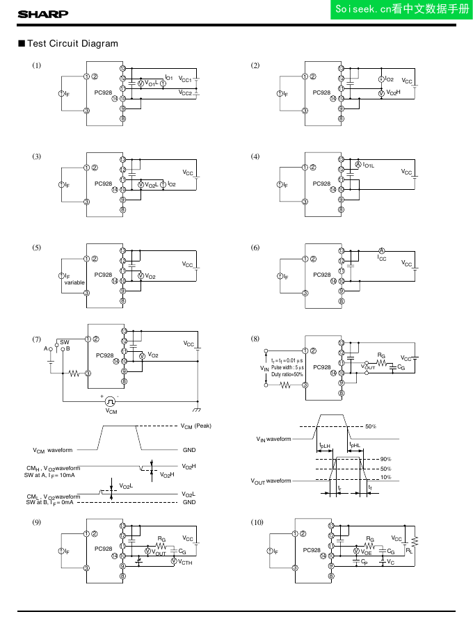
PC928Test Circuit DiagramVCMwaveformCMH, VO2waveformCML, VO2waveformVCM(Peak)GNDGNDVINwaveformVOUTwaveform50%90%50%10%trtf123891011121314›IFPC928V›123891011121314›IFPC928V›VCC123891011121314›PC928VVCCIFvariable123891011121314PC928VVCCSWBAVCM+-123891011121314›PC928VVCCIFVRGVCTHVOUTCG123891011121314›IFPC928V›VCC123891011121314›PC928VCCIFAICC123891011121314›PC928VCCIFA123891011121314›PC928VVCCIFRGCGVOEVCRL123891011121314PC928RGCGVCCVIN(1)(2)(3)(4)(5)(6)(7)(8)(9)(10)SW at A, IF=10mASW at B, IF=0mAtr=tf=0.01msPulse width : 5msDuty ratio=50%tpLHtpHLVO1LIO1VCC1VCC2VO2HVO2LIO2VO2VO2DVO2HDVO2LVO2HVO2LIO1LIO2VOUTCPn�
Soiseek.cn看中文数据手册
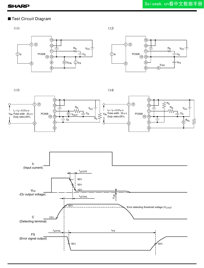
PC928Test Circuit Diagram123891011121314›IFPC928VflVFSLIFSRGCGVCC(11)IF(Input current)90%50%10%tpCOHLVOEtpCOTF90%Error detecting threshold voltage (V )CTH10%DtFS50%50%123891011121314›IFPC928RGCGVCC(12)AIFSHVFS(13)123891011121314PC928VRGCGVCCVOUTVIN123891011121314PC928VRGCGVCCVINRCRFS(14)tr=tf=0.01msPulse width : 25msDuty ratio=25%CPRCtr=tf=0.01msPulse width : 25msDuty ratio=25%VO2C(Detecting terminal)FS(Error signal output)tpCFHL(O2 output voltage)n�
Soiseek.cn看中文数据手册
Fig. 1 Forward Current vs. Ambient Temperature6050403020100025507580100125-250025507580100125-2560050040030020010055050020010050201052100.51.01.52.02.53.03.51.61.41.210.61518212427300.8Value of V =24V assumes 1.CCTa=25˚C10.80.91.11.21.3-250255075100I at Ta=25˚C = 1FLH10.10.010.0010.010.11Ta=25˚CVCC1=12VVCC2=12VIF=10mAFig. 3 Forward Current vs. Forward VoltagePC928Ta=75˚C50˚C25˚C0˚C-20˚CRelative threshold input current IFLHRelative threshold input current IFLHForward current I (mA)FAmbient temperature Ta(˚C)Fig. 2 Power Dissipation vs. Ambient TemperatureAmbient temperature Ta(˚C)Power dissipation Ptot, Po (mW)Forward current I (mA)FForward voltage V (V)FSupply voltage V (V)CCFig. 6 O1 Low Level Output Voltage vs. O1 Output CurrentAmbient temperature Ta (˚C)VCC=24VO1 low level output voltage VO1L (V)Total power dissipationOutput side power dissipationO1 output current IO1 (A)Fig. 5 "L-H" Relative Threshold Input Current vs. Ambient TemperatureFig. 4 "L-H" Relative Threshold Input Current vs. Supply Voltage�
Soiseek.cn看中文数据手册
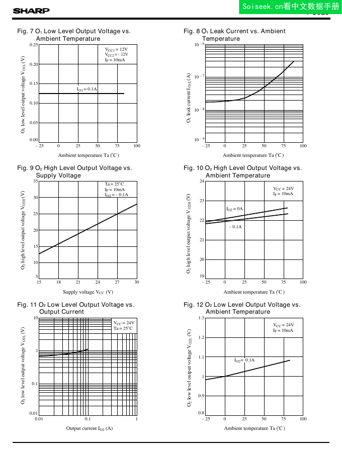
Fig. 7 O1 Low Level Output Voltage vs. Ambient Temperature-2502550751000.250.200.150.100.050.00IO1=0.1A0255075100-2510-610-710-810-93530252015105151821242730Ta=25˚CIF=10mAIO2= -0.1A242322212019-250255075100VCC=24VIF=10mA-0.1A1010.10.010.010.11VCC=24VTa=25˚CFig. 8 O1 Leak Current vs. Ambient TemperaturePC928-250255075100VCC=24VIF=10mA0.80.911.11.21.3IO2=0.1AVCC1=12VVCC2= -12VIF=10mAAmbient temperature Ta (˚C)O1 low level output voltage V (V)O1LAmbient temperature Ta (˚C)O1 leak current I (A)O1LO2 high level output voltage V (V)O2HO2 high level output voltage V (V)O2HSupply voltage V (V)CCAmbient temperature Ta (˚C)IO2=0AO2 low level output voltage VO2L (V)Output current IO2 (A)O2 low level output voltage VO2L (V)Ambient temperature Ta (˚C)Fig. 12 O2 Low Level Output Voltage vs. Ambient TemperatureFig. 9 O2High Level Output Voltage vs. Supply VoltageFig. 10 O2 High Level Output Voltage vs. Ambient TemperatureFig. 11 O2 Low Level Output Voltage vs. Output Current�




 2023年江西萍乡中考道德与法治真题及答案.doc
 2012年重庆南川中考生物真题及答案.doc
 2013年江西师范大学地理学综合及文艺理论基础考研真题.doc
 2020年四川甘孜小升初语文真题及答案I卷.doc
 2020年注册岩土工程师专业基础考试真题及答案.doc
 2023-2024学年福建省厦门市九年级上学期数学月考试题及答案.doc
 2021-2022学年辽宁省沈阳市大东区九年级上学期语文期末试题及答案.doc
 2022-2023学年北京东城区初三第一学期物理期末试卷及答案.doc
 2018上半年江西教师资格初中地理学科知识与教学能力真题及答案.doc
 2012年河北国家公务员申论考试真题及答案-省级.doc
 2020-2021学年江苏省扬州市江都区邵樊片九年级上学期数学第一次质量检测试题及答案.doc
 2022下半年黑龙江教师资格证中学综合素质真题及答案.doc