THE DISPLAYPORT 1.1a
STANDARD HAS
BEEN SUPERSEDED BY
DISPLAYPORT 1.2
THE DISPLAYPORT 1.2 STANDARD IS AVAILABLE FOR
DOWNLOAD FREE OF CHARGE TO VESA MEMBERS.
NON-MEMBERS MAY PURCHASE THE DISPLAYPORT
1.2 STANDARD FROM THE VESA WEBSITE OR
DISPLAYPORT WEBSITE.
�
860 Hillview Court, Suite 150
Milpitas, CA 95035
DisplayPort™ Standard
Phone: 408 957 9270
Fax: 408 957 9277
URL: www.vesa.org
VESA DisplayPort Standard
Version 1, Revision 1a
January 11, 2008
Purpose
The purpose of this document is to define a flexible system and apparatus capable of transporting video, audio
and other data between a Source Device and a Sink Device over a digital communications interface.
Summary
The DisplayPort™ standard specifies an open digital communications interface for use in both internal
connections, such as interfaces within a PC or monitor, and external display connections, including interfaces
between a PC and monitor or projector, between a PC and TV, or between a device such as a DVD player and
TV display.
DisplayPort.1.1a is revised to correct errata items in, and add clarifications to, DisplayPort Standard 1.1.
VESA DisplayPort Standard
©Copyright 2006- 2008 Video Electronics Standards Association
Version 1.1a
Page 1 of 238
�
1.6.1
1.6.2
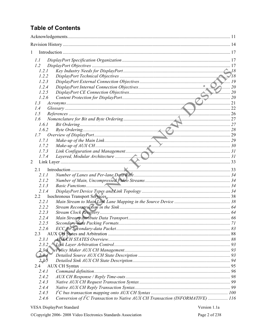
Table of Contents
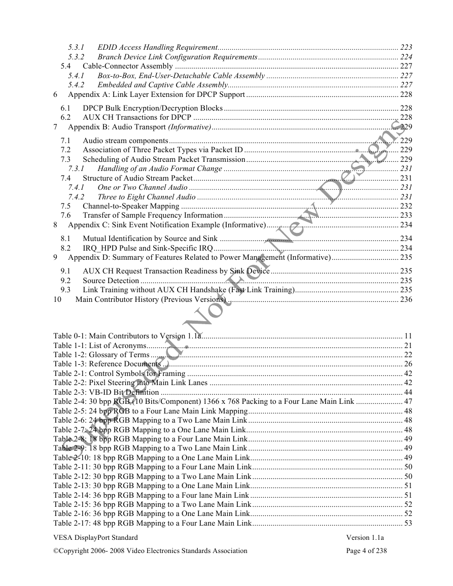
Acknowledgements............................................................................................................................................ 11
Revision History ................................................................................................................................................ 14
1
Introduction ................................................................................................................................................ 17
1.1 DisplayPort Specification Organization ............................................................................................. 17
1.2 DisplayPort Objectives ....................................................................................................................... 17
1.2.1
Key Industry Needs for DisplayPort............................................................................................ 18
1.2.2 DisplayPort Technical Objectives ............................................................................................... 18
1.2.3 DisplayPort External Connection Objectives.............................................................................. 19
1.2.4 DisplayPort Internal Connection Objectives............................................................................... 20
1.2.5 DisplayPort CE Connection Objectives....................................................................................... 20
1.2.6
Content Protection for DisplayPort............................................................................................. 20
1.3
Acronyms............................................................................................................................................. 21
1.4 Glossary .............................................................................................................................................. 22
1.5
References ........................................................................................................................................... 26
1.6 Nomenclature for Bit and Byte Ordering............................................................................................ 27
Bit Ordering................................................................................................................................. 27
Byte Ordering............................................................................................................................... 28
1.7 Overview of DisplayPort..................................................................................................................... 29
1.7.1 Make-up of the Main Link............................................................................................................ 29
1.7.2 Make-up of AUX CH.................................................................................................................... 30
Link Configuration and Management.......................................................................................... 31
1.7.3
1.7.4
Layered, Modular Architecture ................................................................................................... 31
2 Link Layer .................................................................................................................................................. 33
Introduction ......................................................................................................................................... 33
Number of Lanes and Per-lane Data Rate................................................................................... 34
2.1.1
Number of Main, Uncompressed Video Streams ......................................................................... 34
2.1.2
2.1.3
Basic Functions............................................................................................................................ 34
2.1.4 DisplayPort Device Types and Link Topology ............................................................................ 34
Isochronous Transport Services .......................................................................................................... 38
2.2.1 Main Stream to Main Link Lane Mapping in the Source Device ................................................ 38
Stream Reconstruction in the Sink ............................................................................................... 64
2.2.2
2.2.3
Stream Clock Recovery................................................................................................................ 64
2.2.4 Main Stream Attribute Data Transport........................................................................................ 66
2.2.5
Secondary-data Packing Formats................................................................................................ 71
ECC for Secondary-data Packet.................................................................................................. 83
2.2.6
2.3 AUX CH States and Arbitration ......................................................................................................... 88
AUX CH STATES Overview......................................................................................................... 88
2.3.1
Link Layer Arbitration Control.................................................................................................... 93
2.3.2
2.3.3
Policy Maker AUX CH Management........................................................................................... 93
2.3.4 Detailed Source AUX CH State Description ............................................................................... 93
2.3.5 Detailed Sink AUX CH State Description.................................................................................... 94
2.4 AUX CH Syntax ................................................................................................................................. 95
Command definition..................................................................................................................... 96
AUX CH Response / Reply Time-outs.......................................................................................... 98
Native AUX CH Request Transaction Syntax .............................................................................. 99
Native AUX CH Reply Transaction Syntax.................................................................................. 99
I2C bus transaction mapping onto AUX CH Syntax .................................................................. 100
Conversion of I2C Transaction to Native AUX CH Transaction (INFORMATIVE) ................. 116
2.4.1
2.4.2
2.4.3
2.4.4
2.4.5
2.4.6
2.1
2.2
VESA DisplayPort Standard
©Copyright 2006- 2008 Video Electronics Standards Association
Version 1.1a
Page 2 of 238
�
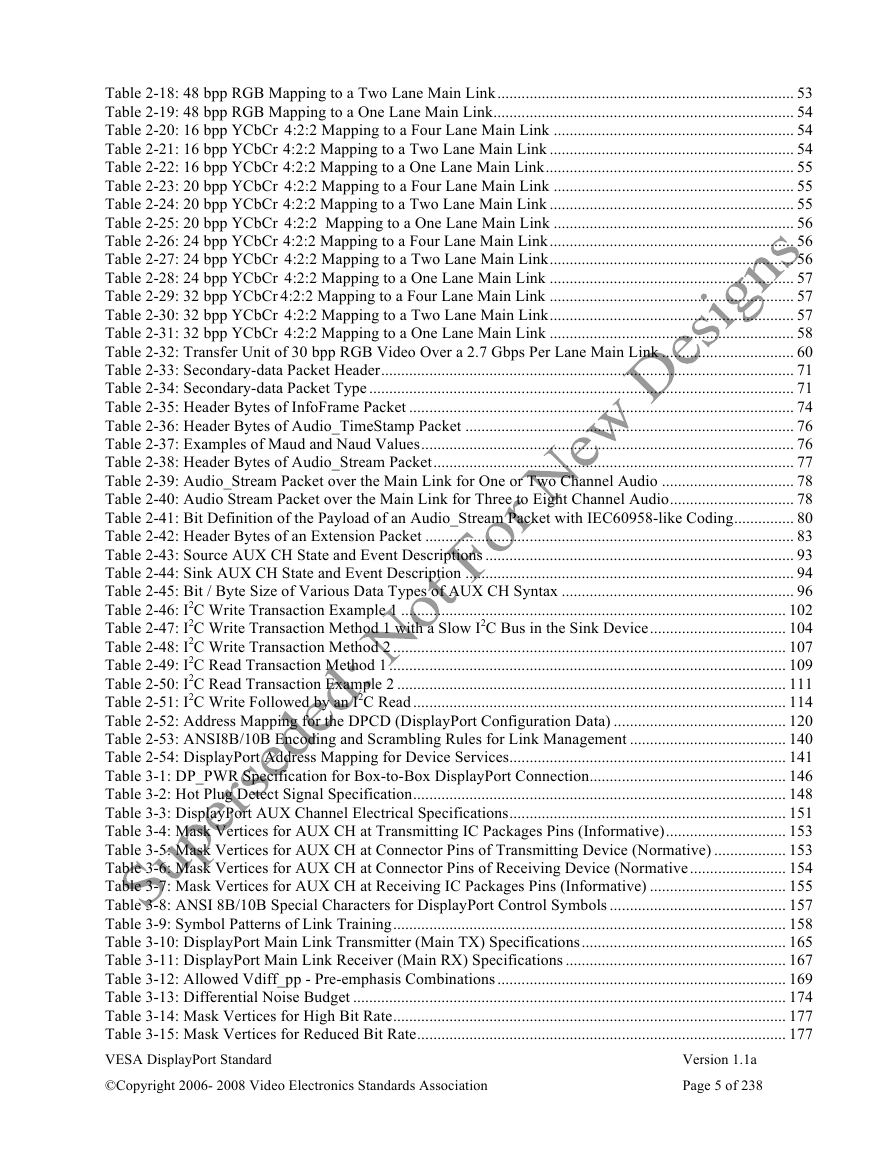
3.1
3.4.1
3.4.2
3.1.1
3.1.2
3.1.3
2.5.1
2.5.2
2.5.3
2.5.4
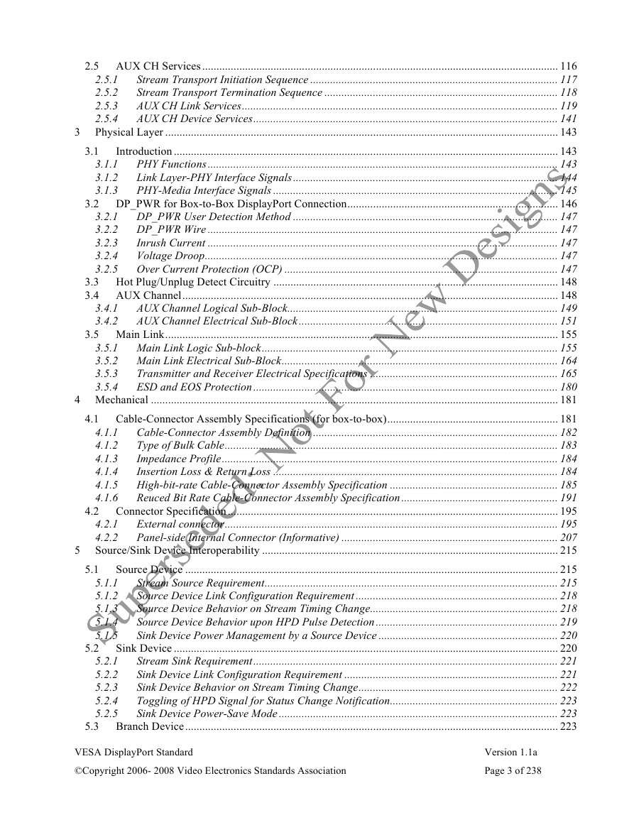
2.5 AUX CH Services ............................................................................................................................. 116
Stream Transport Initiation Sequence ....................................................................................... 117
Stream Transport Termination Sequence .................................................................................. 118
AUX CH Link Services............................................................................................................... 119
AUX CH Device Services........................................................................................................... 141
3 Physical Layer .......................................................................................................................................... 143
Introduction ....................................................................................................................................... 143
PHY Functions........................................................................................................................... 143
Link Layer-PHY Interface Signals............................................................................................. 144
PHY-Media Interface Signals .................................................................................................... 145
3.2 DP_PWR for Box-to-Box DisplayPort Connection.......................................................................... 146
3.2.1 DP_PWR User Detection Method ............................................................................................. 147
3.2.2 DP_PWR Wire ........................................................................................................................... 147
3.2.3
Inrush Current ........................................................................................................................... 147
3.2.4
Voltage Droop............................................................................................................................ 147
3.2.5 Over Current Protection (OCP) ................................................................................................ 147
3.3 Hot Plug/Unplug Detect Circuitry .................................................................................................... 148
3.4 AUX Channel.................................................................................................................................... 148
AUX Channel Logical Sub-Block............................................................................................... 149
AUX Channel Electrical Sub-Block........................................................................................... 151
3.5 Main Link.......................................................................................................................................... 155
3.5.1 Main Link Logic Sub-block........................................................................................................ 155
3.5.2 Main Link Electrical Sub-Block................................................................................................. 164
Transmitter and Receiver Electrical Specifications .................................................................. 165
3.5.3
3.5.4
ESD and EOS Protection........................................................................................................... 180
4 Mechanical ............................................................................................................................................... 181
4.1 Cable-Connector Assembly Specifications (for box-to-box)............................................................ 181
Cable-Connector Assembly Definition ...................................................................................... 182
4.1.1
Type of Bulk Cable..................................................................................................................... 183
4.1.2
Impedance Profile...................................................................................................................... 184
4.1.3
4.1.4
Insertion Loss & Return Loss .................................................................................................... 184
4.1.5 High-bit-rate Cable-Connector Assembly Specification ........................................................... 185
4.1.6
Reuced Bit Rate Cable-Connector Assembly Specification....................................................... 191
4.2 Connector Specification .................................................................................................................... 195
External connector..................................................................................................................... 195
Panel-side Internal Connector (Informative) ............................................................................ 207
5 Source/Sink Device Interoperability ........................................................................................................ 215
Source Device ................................................................................................................................... 215
Stream Source Requirement....................................................................................................... 215
Source Device Link Configuration Requirement ....................................................................... 218
Source Device Behavior on Stream Timing Change.................................................................. 218
Source Device Behavior upon HPD Pulse Detection ................................................................ 219
Sink Device Power Management by a Source Device ............................................................... 220
Sink Device ....................................................................................................................................... 220
Stream Sink Requirement........................................................................................................... 221
Sink Device Link Configuration Requirement ........................................................................... 221
Sink Device Behavior on Stream Timing Change...................................................................... 222
Toggling of HPD Signal for Status Change Notification........................................................... 223
Sink Device Power-Save Mode .................................................................................................. 223
5.3 Branch Device................................................................................................................................... 223
5.2.1
5.2.2
5.2.3
5.2.4
5.2.5
5.1.1
5.1.2
5.1.3
5.1.4
5.1.5
4.2.1
4.2.2
5.1
5.2
VESA DisplayPort Standard
©Copyright 2006- 2008 Video Electronics Standards Association
Version 1.1a
Page 3 of 238
�
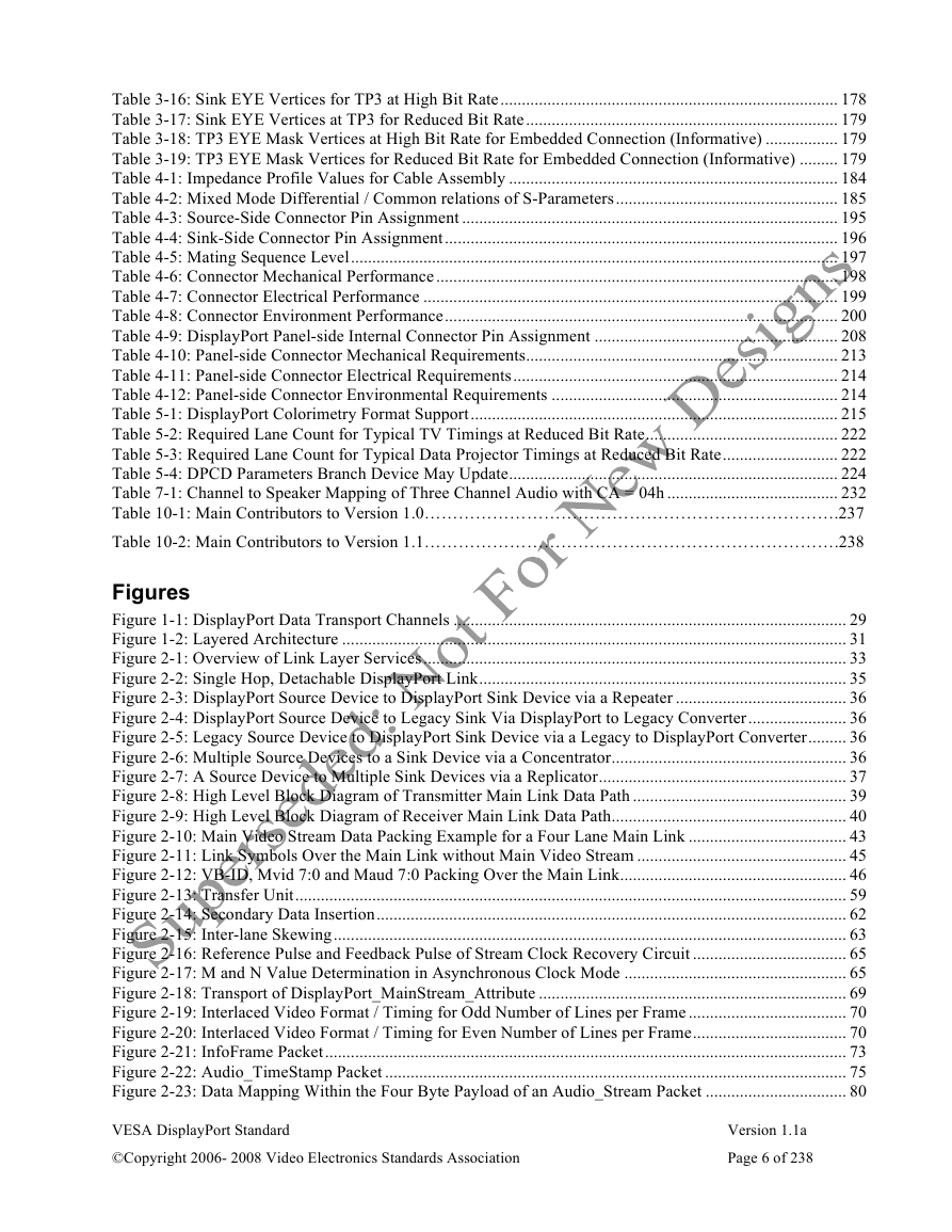
5.3.1
5.3.2
5.4.1
5.4.2
EDID Access Handling Requirement......................................................................................... 223
Branch Device Link Configuration Requirements..................................................................... 224
5.4 Cable-Connector Assembly .............................................................................................................. 227
Box-to-Box, End-User-Detachable Cable Assembly ................................................................. 227
Embedded and Captive Cable Assembly.................................................................................... 227
6 Appendix A: Link Layer Extension for DPCP Support ........................................................................... 228
6.1 DPCP Bulk Encryption/Decryption Blocks ...................................................................................... 228
6.2 AUX CH Transactions for DPCP ..................................................................................................... 228
7 Appendix B: Audio Transport (Informative)............................................................................................ 229
7.1 Audio stream components................................................................................................................. 229
7.2 Association of Three Packet Types via Packet ID ............................................................................ 229
7.3
Scheduling of Audio Stream Packet Transmission........................................................................... 229
7.3.1 Handling of an Audio Format Change ...................................................................................... 231
Structure of Audio Stream Packet..................................................................................................... 231
7.4.1 One or Two Channel Audio ....................................................................................................... 231
7.4.2
Three to Eight Channel Audio ................................................................................................... 231
7.5 Channel-to-Speaker Mapping ........................................................................................................... 232
Transfer of Sample Frequency Information...................................................................................... 233
7.6
8 Appendix C: Sink Event Notification Example (Informative)................................................................. 234
8.1 Mutual Identification by Source and Sink ........................................................................................ 234
8.2
IRQ_HPD Pulse and Sink-Specific IRQ........................................................................................... 234
9 Appendix D: Summary of Features Related to Power Management (Informative)................................. 235
9.1 AUX CH Request Transaction Readiness by Sink Device............................................................... 235
9.2
Source Detection ............................................................................................................................... 235
Link Training without AUX CH Handshake (Fast Link Training)................................................... 235
9.3
10 Main Contributor History (Previous Versions) .................................................................................... 236
7.4
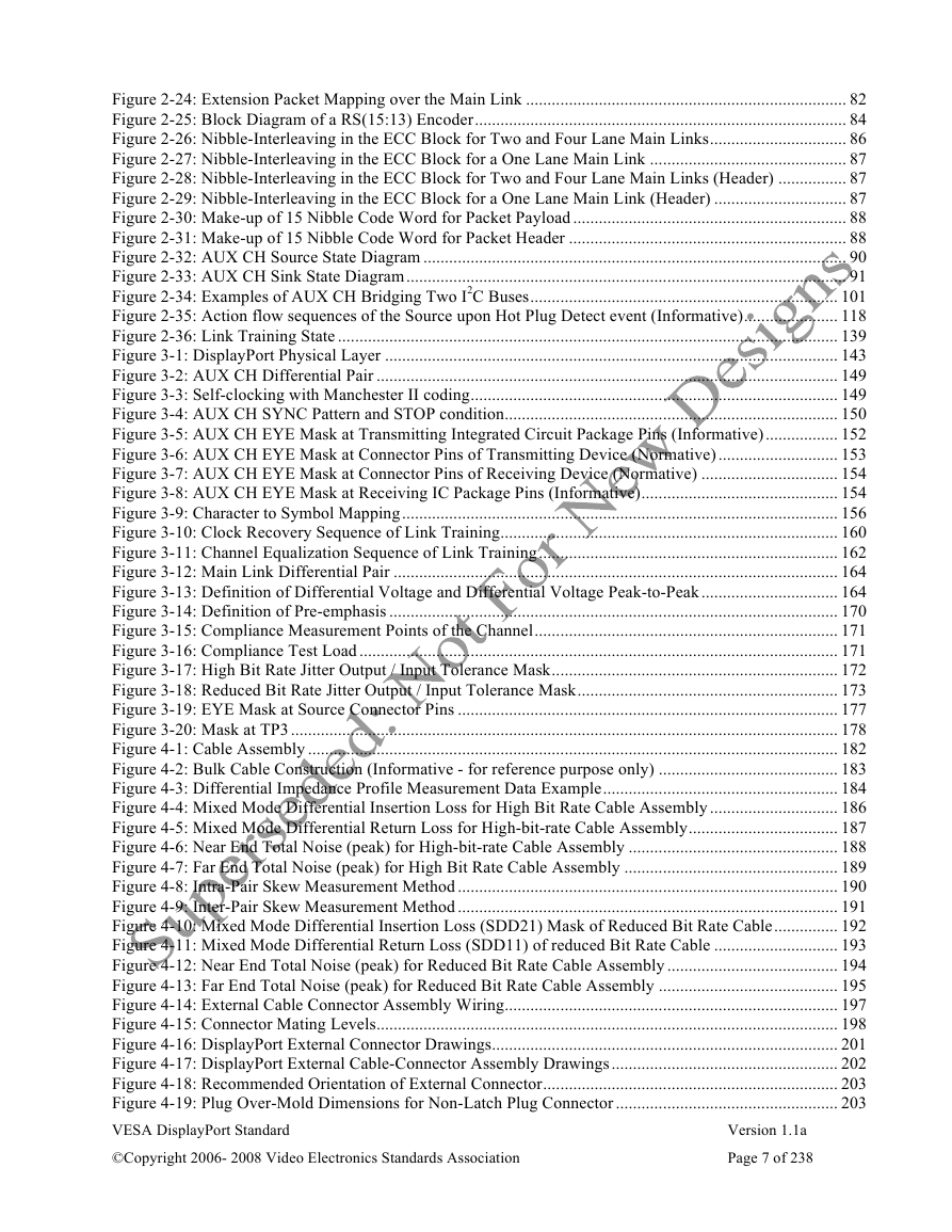
Table 0-1: Main Contributors to Version 1.1a................................................................................................... 11
Table 1-1: List of Acronyms.............................................................................................................................. 21
Table 1-2: Glossary of Terms ............................................................................................................................ 22
Table 1-3: Reference Documents ...................................................................................................................... 26
Table 2-1: Control Symbols for Framing .......................................................................................................... 42
Table 2-2: Pixel Steering into Main Link Lanes ............................................................................................... 42
Table 2-3: VB-ID Bit Definition ....................................................................................................................... 44
Table 2-4: 30 bpp RGB (10 Bits/Component) 1366 x 768 Packing to a Four Lane Main Link ....................... 47
Table 2-5: 24 bpp RGB to a Four Lane Main Link Mapping............................................................................ 48
Table 2-6: 24 bpp RGB Mapping to a Two Lane Main Link............................................................................ 48
Table 2-7: 24 bpp RGB Mapping to a One Lane Main Link............................................................................. 48
Table 2-8: 18 bpp RGB Mapping to a Four Lane Main Link............................................................................ 49
Table 2-9: 18 bpp RGB Mapping to a Two Lane Main Link............................................................................ 49
Table 2-10: 18 bpp RGB Mapping to a One Lane Main Link........................................................................... 49
Table 2-11: 30 bpp RGB Mapping to a Four Lane Main Link.......................................................................... 50
Table 2-12: 30 bpp RGB Mapping to a Two Lane Main Link.......................................................................... 50
Table 2-13: 30 bpp RGB Mapping to a One Lane Main Link........................................................................... 51
Table 2-14: 36 bpp RGB Mapping to a Four lane Main Link ........................................................................... 51
Table 2-15: 36 bpp RGB Mapping to a Two Lane Main Link.......................................................................... 52
Table 2-16: 36 bpp RGB Mapping to a One Lane Main Link........................................................................... 52
Table 2-17: 48 bpp RGB Mapping to a Four Lane Main Link.......................................................................... 53
VESA DisplayPort Standard
©Copyright 2006- 2008 Video Electronics Standards Association
Version 1.1a
Page 4 of 238
�
Table 2-18: 48 bpp RGB Mapping to a Two Lane Main Link.......................................................................... 53
Table 2-19: 48 bpp RGB Mapping to a One Lane Main Link........................................................................... 54
Table 2-20: 16 bpp YCbCr 4:2:2 Mapping to a Four Lane Main Link ............................................................ 54
Table 2-21: 16 bpp YCbCr 4:2:2 Mapping to a Two Lane Main Link ............................................................. 54
Table 2-22: 16 bpp YCbCr 4:2:2 Mapping to a One Lane Main Link.............................................................. 55
Table 2-23: 20 bpp YCbCr 4:2:2 Mapping to a Four Lane Main Link ............................................................ 55
Table 2-24: 20 bpp YCbCr 4:2:2 Mapping to a Two Lane Main Link ............................................................. 55
Table 2-25: 20 bpp YCbCr 4:2:2 Mapping to a One Lane Main Link ............................................................ 56
Table 2-26: 24 bpp YCbCr 4:2:2 Mapping to a Four Lane Main Link............................................................. 56
Table 2-27: 24 bpp YCbCr 4:2:2 Mapping to a Two Lane Main Link............................................................. 56
Table 2-28: 24 bpp YCbCr 4:2:2 Mapping to a One Lane Main Link ............................................................. 57
Table 2-29: 32 bpp YCbCr 4:2:2 Mapping to a Four Lane Main Link ............................................................. 57
Table 2-30: 32 bpp YCbCr 4:2:2 Mapping to a Two Lane Main Link............................................................. 57
Table 2-31: 32 bpp YCbCr 4:2:2 Mapping to a One Lane Main Link ............................................................. 58
Table 2-32: Transfer Unit of 30 bpp RGB Video Over a 2.7 Gbps Per Lane Main Link ................................. 60
Table 2-33: Secondary-data Packet Header....................................................................................................... 71
Table 2-34: Secondary-data Packet Type .......................................................................................................... 71
Table 2-35: Header Bytes of InfoFrame Packet ................................................................................................ 74
Table 2-36: Header Bytes of Audio_TimeStamp Packet .................................................................................. 76
Table 2-37: Examples of Maud and Naud Values............................................................................................. 76
Table 2-38: Header Bytes of Audio_Stream Packet.......................................................................................... 77
Table 2-39: Audio_Stream Packet over the Main Link for One or Two Channel Audio ................................. 78
Table 2-40: Audio Stream Packet over the Main Link for Three to Eight Channel Audio............................... 78
Table 2-41: Bit Definition of the Payload of an Audio_Stream Packet with IEC60958-like Coding............... 80
Table 2-42: Header Bytes of an Extension Packet ............................................................................................ 83
Table 2-43: Source AUX CH State and Event Descriptions ............................................................................. 93
Table 2-44: Sink AUX CH State and Event Description .................................................................................. 94
Table 2-45: Bit / Byte Size of Various Data Types of AUX CH Syntax .......................................................... 96
Table 2-46: I2C Write Transaction Example 1 ................................................................................................ 102
Table 2-47: I2C Write Transaction Method 1 with a Slow I2C Bus in the Sink Device.................................. 104
Table 2-48: I2C Write Transaction Method 2 .................................................................................................. 107
Table 2-49: I2C Read Transaction Method 1................................................................................................... 109
Table 2-50: I2C Read Transaction Example 2 ................................................................................................. 111
Table 2-51: I2C Write Followed by an I2C Read ............................................................................................. 114
Table 2-52: Address Mapping for the DPCD (DisplayPort Configuration Data) ........................................... 120
Table 2-53: ANSI8B/10B Encoding and Scrambling Rules for Link Management ....................................... 140
Table 2-54: DisplayPort Address Mapping for Device Services..................................................................... 141
Table 3-1: DP_PWR Specification for Box-to-Box DisplayPort Connection................................................. 146
Table 3-2: Hot Plug Detect Signal Specification............................................................................................. 148
Table 3-3: DisplayPort AUX Channel Electrical Specifications..................................................................... 151
Table 3-4: Mask Vertices for AUX CH at Transmitting IC Packages Pins (Informative).............................. 153
Table 3-5: Mask Vertices for AUX CH at Connector Pins of Transmitting Device (Normative) .................. 153
Table 3-6: Mask Vertices for AUX CH at Connector Pins of Receiving Device (Normative........................ 154
Table 3-7: Mask Vertices for AUX CH at Receiving IC Packages Pins (Informative) .................................. 155
Table 3-8: ANSI 8B/10B Special Characters for DisplayPort Control Symbols ............................................ 157
Table 3-9: Symbol Patterns of Link Training.................................................................................................. 158
Table 3-10: DisplayPort Main Link Transmitter (Main TX) Specifications................................................... 165
Table 3-11: DisplayPort Main Link Receiver (Main RX) Specifications ....................................................... 167
Table 3-12: Allowed Vdiff_pp - Pre-emphasis Combinations ........................................................................ 169
Table 3-13: Differential Noise Budget ............................................................................................................ 174
Table 3-14: Mask Vertices for High Bit Rate.................................................................................................. 177
Table 3-15: Mask Vertices for Reduced Bit Rate............................................................................................ 177
VESA DisplayPort Standard
©Copyright 2006- 2008 Video Electronics Standards Association
Version 1.1a
Page 5 of 238
�
Table 3-16: Sink EYE Vertices for TP3 at High Bit Rate............................................................................... 178
Table 3-17: Sink EYE Vertices at TP3 for Reduced Bit Rate......................................................................... 179
Table 3-18: TP3 EYE Mask Vertices at High Bit Rate for Embedded Connection (Informative) ................. 179
Table 3-19: TP3 EYE Mask Vertices for Reduced Bit Rate for Embedded Connection (Informative) ......... 179
Table 4-1: Impedance Profile Values for Cable Assembly ............................................................................. 184
Table 4-2: Mixed Mode Differential / Common relations of S-Parameters.................................................... 185
Table 4-3: Source-Side Connector Pin Assignment ........................................................................................ 195
Table 4-4: Sink-Side Connector Pin Assignment............................................................................................ 196
Table 4-5: Mating Sequence Level.................................................................................................................. 197
Table 4-6: Connector Mechanical Performance .............................................................................................. 198
Table 4-7: Connector Electrical Performance ................................................................................................. 199
Table 4-8: Connector Environment Performance............................................................................................ 200
Table 4-9: DisplayPort Panel-side Internal Connector Pin Assignment ......................................................... 208
Table 4-10: Panel-side Connector Mechanical Requirements......................................................................... 213
Table 4-11: Panel-side Connector Electrical Requirements............................................................................ 214
Table 4-12: Panel-side Connector Environmental Requirements ................................................................... 214
Table 5-1: DisplayPort Colorimetry Format Support...................................................................................... 215
Table 5-2: Required Lane Count for Typical TV Timings at Reduced Bit Rate............................................. 222
Table 5-3: Required Lane Count for Typical Data Projector Timings at Reduced Bit Rate........................... 222
Table 5-4: DPCD Parameters Branch Device May Update............................................................................. 224
Table 7-1: Channel to Speaker Mapping of Three Channel Audio with CA = 04h ........................................ 232
Table 10-1: Main Contributors to Version 1.0……………………………………………………………….237
Table 10-2: Main Contributors to Version 1.1……………………………………………………………….238
Figures
Figure 1-1: DisplayPort Data Transport Channels ............................................................................................ 29
Figure 1-2: Layered Architecture ...................................................................................................................... 31
Figure 2-1: Overview of Link Layer Services................................................................................................... 33
Figure 2-2: Single Hop, Detachable DisplayPort Link...................................................................................... 35
Figure 2-3: DisplayPort Source Device to DisplayPort Sink Device via a Repeater ........................................ 36
Figure 2-4: DisplayPort Source Device to Legacy Sink Via DisplayPort to Legacy Converter....................... 36
Figure 2-5: Legacy Source Device to DisplayPort Sink Device via a Legacy to DisplayPort Converter......... 36
Figure 2-6: Multiple Source Devices to a Sink Device via a Concentrator....................................................... 36
Figure 2-7: A Source Device to Multiple Sink Devices via a Replicator.......................................................... 37
Figure 2-8: High Level Block Diagram of Transmitter Main Link Data Path .................................................. 39
Figure 2-9: High Level Block Diagram of Receiver Main Link Data Path....................................................... 40
Figure 2-10: Main Video Stream Data Packing Example for a Four Lane Main Link ..................................... 43
Figure 2-11: Link Symbols Over the Main Link without Main Video Stream ................................................. 45
Figure 2-12: VB-ID, Mvid 7:0 and Maud 7:0 Packing Over the Main Link..................................................... 46
Figure 2-13: Transfer Unit................................................................................................................................. 59
Figure 2-14: Secondary Data Insertion.............................................................................................................. 62
Figure 2-15: Inter-lane Skewing........................................................................................................................ 63
Figure 2-16: Reference Pulse and Feedback Pulse of Stream Clock Recovery Circuit .................................... 65
Figure 2-17: M and N Value Determination in Asynchronous Clock Mode .................................................... 65
Figure 2-18: Transport of DisplayPort_MainStream_Attribute ........................................................................ 69
Figure 2-19: Interlaced Video Format / Timing for Odd Number of Lines per Frame ..................................... 70
Figure 2-20: Interlaced Video Format / Timing for Even Number of Lines per Frame.................................... 70
Figure 2-21: InfoFrame Packet.......................................................................................................................... 73
Figure 2-22: Audio_TimeStamp Packet ............................................................................................................ 75
Figure 2-23: Data Mapping Within the Four Byte Payload of an Audio_Stream Packet ................................. 80
VESA DisplayPort Standard
©Copyright 2006- 2008 Video Electronics Standards Association
Version 1.1a
Page 6 of 238
�
Figure 2-24: Extension Packet Mapping over the Main Link ........................................................................... 82
Figure 2-25: Block Diagram of a RS(15:13) Encoder....................................................................................... 84
Figure 2-26: Nibble-Interleaving in the ECC Block for Two and Four Lane Main Links................................ 86
Figure 2-27: Nibble-Interleaving in the ECC Block for a One Lane Main Link .............................................. 87
Figure 2-28: Nibble-Interleaving in the ECC Block for Two and Four Lane Main Links (Header) ................ 87
Figure 2-29: Nibble-Interleaving in the ECC Block for a One Lane Main Link (Header) ............................... 87
Figure 2-30: Make-up of 15 Nibble Code Word for Packet Payload ................................................................ 88
Figure 2-31: Make-up of 15 Nibble Code Word for Packet Header ................................................................. 88
Figure 2-32: AUX CH Source State Diagram ................................................................................................... 90
Figure 2-33: AUX CH Sink State Diagram....................................................................................................... 91
Figure 2-34: Examples of AUX CH Bridging Two I2C Buses........................................................................ 101
Figure 2-35: Action flow sequences of the Source upon Hot Plug Detect event (Informative)...................... 118
Figure 2-36: Link Training State ..................................................................................................................... 139
Figure 3-1: DisplayPort Physical Layer .......................................................................................................... 143
Figure 3-2: AUX CH Differential Pair ............................................................................................................ 149
Figure 3-3: Self-clocking with Manchester II coding...................................................................................... 149
Figure 3-4: AUX CH SYNC Pattern and STOP condition.............................................................................. 150
Figure 3-5: AUX CH EYE Mask at Transmitting Integrated Circuit Package Pins (Informative)................. 152
Figure 3-6: AUX CH EYE Mask at Connector Pins of Transmitting Device (Normative)............................ 153
Figure 3-7: AUX CH EYE Mask at Connector Pins of Receiving Device (Normative) ................................ 154
Figure 3-8: AUX CH EYE Mask at Receiving IC Package Pins (Informative).............................................. 154
Figure 3-9: Character to Symbol Mapping...................................................................................................... 156
Figure 3-10: Clock Recovery Sequence of Link Training............................................................................... 160
Figure 3-11: Channel Equalization Sequence of Link Training...................................................................... 162
Figure 3-12: Main Link Differential Pair ........................................................................................................ 164
Figure 3-13: Definition of Differential Voltage and Differential Voltage Peak-to-Peak................................ 164
Figure 3-14: Definition of Pre-emphasis ......................................................................................................... 170
Figure 3-15: Compliance Measurement Points of the Channel....................................................................... 171
Figure 3-16: Compliance Test Load ................................................................................................................ 171
Figure 3-17: High Bit Rate Jitter Output / Input Tolerance Mask................................................................... 172
Figure 3-18: Reduced Bit Rate Jitter Output / Input Tolerance Mask............................................................. 173
Figure 3-19: EYE Mask at Source Connector Pins ......................................................................................... 177
Figure 3-20: Mask at TP3 ................................................................................................................................ 178
Figure 4-1: Cable Assembly ............................................................................................................................ 182
Figure 4-2: Bulk Cable Construction (Informative - for reference purpose only) .......................................... 183
Figure 4-3: Differential Impedance Profile Measurement Data Example....................................................... 184
Figure 4-4: Mixed Mode Differential Insertion Loss for High Bit Rate Cable Assembly .............................. 186
Figure 4-5: Mixed Mode Differential Return Loss for High-bit-rate Cable Assembly................................... 187
Figure 4-6: Near End Total Noise (peak) for High-bit-rate Cable Assembly ................................................. 188
Figure 4-7: Far End Total Noise (peak) for High Bit Rate Cable Assembly .................................................. 189
Figure 4-8: Intra-Pair Skew Measurement Method ......................................................................................... 190
Figure 4-9: Inter-Pair Skew Measurement Method ......................................................................................... 191
Figure 4-10: Mixed Mode Differential Insertion Loss (SDD21) Mask of Reduced Bit Rate Cable............... 192
Figure 4-11: Mixed Mode Differential Return Loss (SDD11) of reduced Bit Rate Cable ............................. 193
Figure 4-12: Near End Total Noise (peak) for Reduced Bit Rate Cable Assembly ........................................ 194
Figure 4-13: Far End Total Noise (peak) for Reduced Bit Rate Cable Assembly .......................................... 195
Figure 4-14: External Cable Connector Assembly Wiring.............................................................................. 197
Figure 4-15: Connector Mating Levels............................................................................................................ 198
Figure 4-16: DisplayPort External Connector Drawings................................................................................. 201
Figure 4-17: DisplayPort External Cable-Connector Assembly Drawings..................................................... 202
Figure 4-18: Recommended Orientation of External Connector..................................................................... 203
Figure 4-19: Plug Over-Mold Dimensions for Non-Latch Plug Connector .................................................... 203
VESA DisplayPort Standard
©Copyright 2006- 2008 Video Electronics Standards Association
Version 1.1a
Page 7 of 238
�


 2023年江西萍乡中考道德与法治真题及答案.doc
 2012年重庆南川中考生物真题及答案.doc
 2013年江西师范大学地理学综合及文艺理论基础考研真题.doc
 2020年四川甘孜小升初语文真题及答案I卷.doc
 2020年注册岩土工程师专业基础考试真题及答案.doc
 2023-2024学年福建省厦门市九年级上学期数学月考试题及答案.doc
 2021-2022学年辽宁省沈阳市大东区九年级上学期语文期末试题及答案.doc
 2022-2023学年北京东城区初三第一学期物理期末试卷及答案.doc
 2018上半年江西教师资格初中地理学科知识与教学能力真题及答案.doc
 2012年河北国家公务员申论考试真题及答案-省级.doc
 2020-2021学年江苏省扬州市江都区邵樊片九年级上学期数学第一次质量检测试题及答案.doc
 2022下半年黑龙江教师资格证中学综合素质真题及答案.doc