5
4
3
2
1
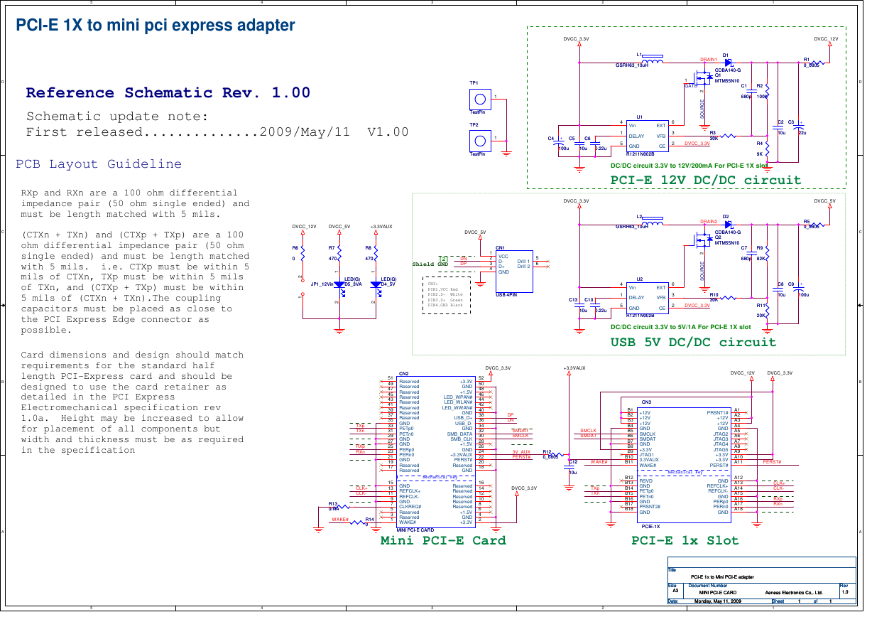
PCI-E 1X to mini pci express adapter
Reference Schematic Rev. 1.00
Schematic update note:
First released..............2009/May/11 V1.00
TP1
TP1
TestPin
TestPin
TP2
TP2
TestPin
TestPin
1
1
DVCC_3.3V
L1
L1
GSRH63_10uH
GSRH63_10uH
D1
D1
DRAIN1
DVCC_12V
R1
R1
0_0805
0_0805
CDBA140-G
CDBA140-G
Q1
Q1
MTM55N10
MTM55N10
C1
C1
R2
R2
680p
680p
100K
100K
1
GATE
2
E
C
R
U
O
S
R3
R3
30K
30K
DVCC_3.3V
C2
C2
C3
C3
+
+
10u
10u
22u
22u
R4
R4
9K
9K
C4
C4
+
+
C5
C5
C6
C6
100u
100u
10u
10u
0.22u
0.22u
4
1
5
U1
U1
Vin
DELAY
GND
R1211N002B
R1211N002B
6
3
2
EXT
VFB
CE
DC/DC circuit 3.3V to 12V/200mA For PCI-E 1X slot
PCI-E 12V DC/DC circuit
DVCC_3.3V
L2
L2
GSRH63_10uH
GSRH63_10uH
C13
C13
C10
C10
10u
10u
0.22u
0.22u
4
1
5
U2
U2
Vin
DELAY
GND
R1211N002B
R1211N002B
6
3
2
EXT
VFB
CE
DVCC_5V
R5
R5
0_0805
0_0805
C8
C8
C9
C9
+
+
10u
10u
100u
100u
D2
D2
DRAIN2
CDBA140-G
CDBA140-G
Q2
Q2
MTM55N10
MTM55N10
2
E
C
R
U
O
S
R10
R10
30K
30K
DVCC_3.3V
C7
C7
R9
R9
680p
680p
82K
82K
R11
R11
20K
20K
DC/DC circuit 3.3V to 5V/1A For PCI-E 1X slot
USB 5V DC/DC circuit
DVCC_12V
DVCC_5V
+3.3VAUX
DVCC_5V
R6
R6
0
0
2
1
R7
R7
470
470
R8
R8
470
470
1
1
JP1_12Vin
JP1_12Vin
LED(G)
LED(G)
D5_3VA
D5_3VA
LED(G)
LED(G)
D4_5V
D4_5V
2
2
[2]
Shield GND
DN
DP
CN3:
PIN1.VCC Red
PIN2.D- White
PIN3.D+ Green
PIN4.GND Black
CN1
CN1
1
2 VCC
3 D-
4 D+
GND
5
6
Drill 1
Drill 2
USB 4PIN
USB 4PIN
D
C
B
A
PCB Layout Guideline
RXp and RXn are a 100 ohm differential
impedance pair (50 ohm single ended) and
must be length matched with 5 mils.
(CTXn + TXn) and (CTXp + TXp) are a 100
ohm differential impedance pair (50 ohm
single ended) and must be length matched
with 5 mils. i.e. CTXp must be within 5
mils of CTXn, TXp must be within 5 mils
of TXn, and (CTXp + TXp) must be within
5 mils of (CTXn + TXn).The coupling
capacitors must be placed as close to
the PCI Express Edge connector as
possible.
Card dimensions and design should match
requirements for the standard half
length PCI-Express card and should be
designed to use the card retainer as
detailed in the PCI Express
Electromechanical specification rev
1.0a. Height may be increased to allow
for placement of all components but
width and thickness must be as required
in the specification
CN2
CN2
51
49 Reserved
47 Reserved
Reserved
45
43 Reserved
41 Reserved
Reserved
39
Reserved
37
Reserved
35
GND
33
PETp0
31
PETn0
29
GND
27
GND
25
PERp0
23
PERn0
21
GND
19
Reserved
17
Reserved
15
13
11
9
7
5
3
1
GND
REFCLK+
REFCLK-
GND
CLKREQ#
Reserved
Reserved
WAKE#
+3.3V
GND
+1.5V
LED_WPAN#
LED_WLAN#
LED_WWAN#
GND
USB_D+
USB_D-
GND
SMB_DATA
SMB_CLK
+1.5V
GND
+3.3VAUX
PERST#
Reserved
GND
Mechanical Key
Mechanical Key
Reserved
Reserved
Reserved
Reserved
Reserved
+1.5V
GND
+3.3V
52
50
48
46
44
42
40
38
36
34
32
30
28
26
24
22
20
18
16
14
12
10
8
6
4
2
TXp
TXn
RXp
RXn
CLK+
CLK-
R13
R13
0/NA
0/NA
W AKE#
R14
R14
0
0
MINI PCI-E CARD
MINI PCI-E CARD
Mini PCI-E Card
DVCC_3.3V
+3.3VAUX
DVCC_12V
DVCC_3.3V
DP
DN
SMDAT
SMCLK
3V_AUX
PERST#
R12
R12
0_0805
0_0805
SMCLK
SMDAT
W AKE#
C12
C12
10u
10u
DVCC_3.3V
TXp
TXn
B1
B2
B3
B4
B5
B6
B7
B8
B9
B10
B11
B12
B13
B14
B15
B16
B17
B18
CN3
CN3
+12V
+12V
+12V
GND
SMCLK
SMDAT
GND
+3.3V
JTAG1
3.3VAUX
WAKE#
RSVD
GND
PETp0
PETn0
GND
PRSNT2#
GND
PCIE-1X
PCIE-1X
PRSNT1#
+12V
+12V
GND
JTAG2
JTAG3
JTAG4
JTAG5
+3.3V
+3.3V
PERST#
GND
REFCLK+
REFCLK-
GND
PERp0
PERn0
GND
A1
A2
A3
A4
A5
A6
A7
A8
A9
A10
A11
A12
A13
A14
A15
A16
A17
A18
PERST#
CLK+
CLK-
RXp
RXn
Mechanical Key
Mechanical Key
PCI-E 1x Slot
Title
Title
Title
Size
Size
Size
A3
A3
A3
Date:
Date:
Date:
PCI-E 1x to Mini PCI-E adapter
PCI-E 1x to Mini PCI-E adapter
PCI-E 1x to Mini PCI-E adapter
Document Number
Document Number
Document Number
MINI PCI-E CARD Aeneas Electronics Co,. Ltd.
MINI PCI-E CARD Aeneas Electronics Co,. Ltd.
MINI PCI-E CARD Aeneas Electronics Co,. Ltd.
Monday, May 11, 2009
Monday, May 11, 2009
Monday, May 11, 2009
Sheet
Sheet
Sheet
1
1
1
of
of
of
1
1
1
Rev
Rev
Rev
1.0
1.0
1.0
5
4
3
2
1
D
C
B
A
�


 2023年江西萍乡中考道德与法治真题及答案.doc
 2012年重庆南川中考生物真题及答案.doc
 2013年江西师范大学地理学综合及文艺理论基础考研真题.doc
 2020年四川甘孜小升初语文真题及答案I卷.doc
 2020年注册岩土工程师专业基础考试真题及答案.doc
 2023-2024学年福建省厦门市九年级上学期数学月考试题及答案.doc
 2021-2022学年辽宁省沈阳市大东区九年级上学期语文期末试题及答案.doc
 2022-2023学年北京东城区初三第一学期物理期末试卷及答案.doc
 2018上半年江西教师资格初中地理学科知识与教学能力真题及答案.doc
 2012年河北国家公务员申论考试真题及答案-省级.doc
 2020-2021学年江苏省扬州市江都区邵樊片九年级上学期数学第一次质量检测试题及答案.doc
 2022下半年黑龙江教师资格证中学综合素质真题及答案.doc