Data Sheet
SiI9135/SiI9135A HDMI Receiver with
Enhanced Audio and Deep Color Outputs
Silicon Im age
AVsolution Technology
Confidential
Internal Use Only
for
Data Sheet
Document # SiI-DS-0206-F01
This document was watermarked on 04-08-2010 at 15:36:08 local time.
�
SiI9135/SiI9135A HDMI Receiver with Enhanced Audio and Deep Color Outputs
Data Sheet
Silicon Image, Inc.
April, 2010
Copyright Notice
Copyright © 2008-2010 Silicon Image, Inc. All rights reserved. These materials contain proprietary and confidential
information (including trade secrets, copyright, and other interests) of Silicon Image, Inc. You may not use these
materials except only for your bona fide non-commercial evaluation of your potential purchase of products and/or
services from Silicon Image or its affiliates, and/or only in connection with your purchase of products and/or services
from Silicon Image or its affiliates, and only in accordance with the terms and conditions herein. You have no right to
copy, modify, transfer, sublicense, publicly display, create derivative works of or distribute these materials, or otherwise
make these materials available, in whole or in part, to any third party.
Patents
The subject matter described herein contains one or more inventions claimed in patents and / or patents pending owned
by Silicon Image, Inc., including but not limited to the inventions claimed in US patents #6,914,637, #6,151,334,
#6,026,124, #5,974,464 and #5,825,824.
Trademark Acknowledgment
Silicon Image™, VastLane™, SteelVine™, PinnaClear™, Simplay™, Simplay HD™, Satalink™, InstaPort™,
TMDS™, and LiquidHD™ are trademarks or registered trademarks of Silicon Image, Inc. in the United States and other
countries. HDMI®, the HDMI logo and High-Definition Multimedia Interface™ are trademarks or registered trademarks
of, and are used under license from, HDMI Licensing, LLC. x.v.Color™ is a trademark of Sony Corporation.
Export Controlled Document
This document contains information subject to the Export Administration Regulations (EAR) and has a classification of
EAR99 or is controlled for Anti-Terrorism (AT) purposes. Transfer of this information by any means to an EAR Country
Group E:1 or foreign national thereof (whether in the U.S. or abroad) may require an export license or other approval from
the U.S. Department of Commerce. For more information, contact the Silicon Image Director of Global Trade Compliance.
Silicon Im age
AVsolution Technology
Confidential
Internal Use Only
for
Comment
Initial Production Data Sheet
Updates to template and timing measurements
Updated to DSD Audio specifications
Content corrections, reformat, copyedit for clarity
Updates to frequencies supported by MCLK and to Power-Down current spec
Updated ePad dimensions
Updated page 1 and layout to prepare Data Brief; minor editing throughout.
Further Information
To request other materials, documentation, and information, contact your local Silicon Image, Inc. sales office or visit
the Silicon Image, Inc. web site at www.siliconimage.com.
Revision History
Revision
A
B
C
D
E
F
F01
Date
01/07
02/07
06/07
12/07
02/08
06/08
4/2010
© 2008-2010 Silicon Image, Inc. All rights reserved
ii
© 2008-2010 Silicon Image, Inc. All rights reserved.
CONFIDENTIAL
SiI-DS-0206-F01
�
Silicon Image, Inc.
SiI9135/SiI9135A HDMI Receiver with Enhanced Audio and Deep Color Outputs
Data Sheet
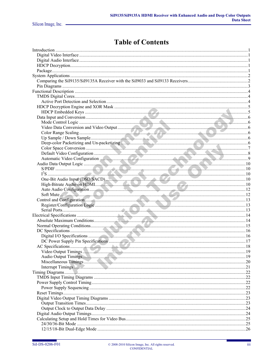
Table of Contents
Silicon Im age
AVsolution Technology
Confidential
Internal Use Only
for
Introduction ..........................................................................................................................................................................1
Digital Video Interface .....................................................................................................................................................1
Digital Audio Interface.....................................................................................................................................................1
HDCP Decryption.............................................................................................................................................................1
Package.............................................................................................................................................................................1
System Applications.............................................................................................................................................................2
Comparing the SiI9135/SiI9135A Receiver with the SiI9033 and SiI9133 Receivers.....................................................2
Pin Diagrams ....................................................................................................................................................................3
Functional Description .........................................................................................................................................................4
TMDS Digital Cores.........................................................................................................................................................4
Active Port Detection and Selection.............................................................................................................................4
HDCP Decryption Engine and XOR Mask ......................................................................................................................5
HDCP Embedded Keys ................................................................................................................................................5
Data Input and Conversion ...............................................................................................................................................6
Mode Control Logic .....................................................................................................................................................6
Video Data Conversion and Video Output ...................................................................................................................6
Color Range Scaling.....................................................................................................................................................6
Up Sample / Down Sample...........................................................................................................................................6
Deep-color Packetizing and Un-packetizing ................................................................................................................6
Color Space Conversion ...............................................................................................................................................7
Default Video Configuration ........................................................................................................................................8
Automatic Video Configuration ...................................................................................................................................9
Audio Data Output Logic ...............................................................................................................................................10
S/PDIF ........................................................................................................................................................................10
I2S ...............................................................................................................................................................................10
One-Bit Audio Input (DSD/SACD)............................................................................................................................10
High-Bitrate Audio on HDMI.....................................................................................................................................10
Auto Audio Configuration..........................................................................................................................................12
Soft Mute....................................................................................................................................................................12
Control and Configuration..............................................................................................................................................13
Register/Configuration Logic .....................................................................................................................................13
Serial Ports..................................................................................................................................................................13
Electrical Specifications .....................................................................................................................................................14
Absolute Maximum Conditions......................................................................................................................................14
Normal Operating Conditions.........................................................................................................................................15
DC Specifications...........................................................................................................................................................16
Digital I/O Specifications ...........................................................................................................................................16
DC Power Supply Pin Specifications .........................................................................................................................17
AC Specifications...........................................................................................................................................................18
Video Output Timings ................................................................................................................................................19
Audio Output Timings................................................................................................................................................19
Miscellaneous Timings...............................................................................................................................................20
Interrupt Timings........................................................................................................................................................21
Timing Diagrams................................................................................................................................................................22
TMDS Input Timing Diagrams ......................................................................................................................................22
Power Supply Control Timing........................................................................................................................................22
Power Supply Sequencing ..........................................................................................................................................22
Reset Timings.................................................................................................................................................................23
Digital Video Output Timing Diagrams .........................................................................................................................23
Output Transition Times.............................................................................................................................................23
Output Clock to Output Data Delay ...........................................................................................................................24
Digital Audio Output Timings........................................................................................................................................24
Calculating Setup and Hold Times for Video Bus..........................................................................................................25
24/30/36-Bit Mode .....................................................................................................................................................25
12/15/18-Bit Dual-Edge Mode ...................................................................................................................................26
SiI-DS-0206-F01
© 2008-2010 Silicon Image, Inc. All rights reserved.
CONFIDENTIAL
iii
�
SiI9135/SiI9135A HDMI Receiver with Enhanced Audio and Deep Color Outputs
Data Sheet
Silicon Image, Inc.
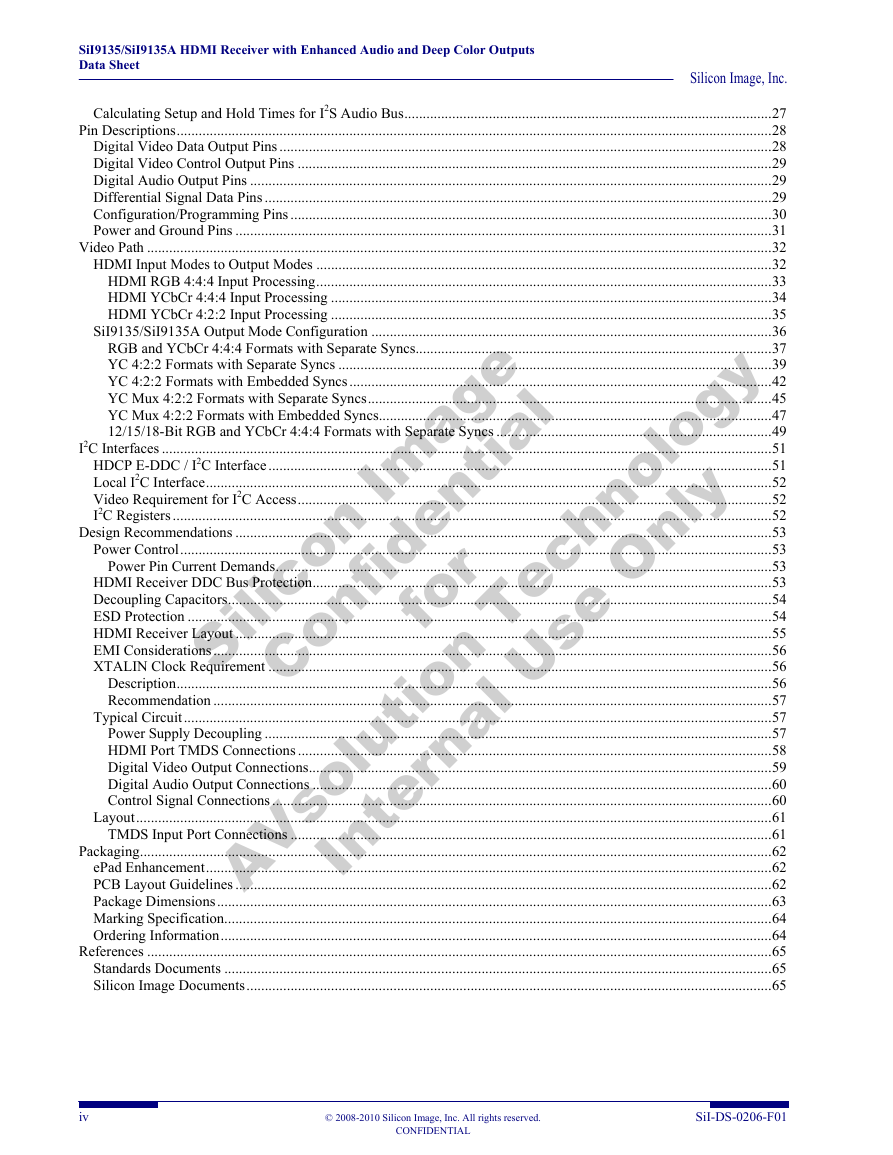
Calculating Setup and Hold Times for I2S Audio Bus....................................................................................................27
Pin Descriptions..................................................................................................................................................................28
Digital Video Data Output Pins ......................................................................................................................................28
Digital Video Control Output Pins .................................................................................................................................29
Digital Audio Output Pins ..............................................................................................................................................29
Differential Signal Data Pins ..........................................................................................................................................29
Configuration/Programming Pins ...................................................................................................................................30
Power and Ground Pins ..................................................................................................................................................31
Video Path ..........................................................................................................................................................................32
HDMI Input Modes to Output Modes ............................................................................................................................32
HDMI RGB 4:4:4 Input Processing............................................................................................................................33
HDMI YCbCr 4:4:4 Input Processing ........................................................................................................................34
HDMI YCbCr 4:2:2 Input Processing ........................................................................................................................35
SiI9135/SiI9135A Output Mode Configuration .............................................................................................................36
RGB and YCbCr 4:4:4 Formats with Separate Syncs.................................................................................................37
YC 4:2:2 Formats with Separate Syncs ......................................................................................................................39
YC 4:2:2 Formats with Embedded Syncs...................................................................................................................42
YC Mux 4:2:2 Formats with Separate Syncs..............................................................................................................45
YC Mux 4:2:2 Formats with Embedded Syncs...........................................................................................................47
12/15/18-Bit RGB and YCbCr 4:4:4 Formats with Separate Syncs ...........................................................................49
I2C Interfaces ......................................................................................................................................................................51
HDCP E-DDC / I2C Interface.........................................................................................................................................51
Local I2C Interface..........................................................................................................................................................52
Video Requirement for I2C Access.................................................................................................................................52
I2C Registers ...................................................................................................................................................................52
Design Recommendations ..................................................................................................................................................53
Power Control.................................................................................................................................................................53
Power Pin Current Demands.......................................................................................................................................53
HDMI Receiver DDC Bus Protection.............................................................................................................................53
Decoupling Capacitors....................................................................................................................................................54
ESD Protection ...............................................................................................................................................................54
HDMI Receiver Layout ..................................................................................................................................................55
EMI Considerations........................................................................................................................................................56
XTALIN Clock Requirement .........................................................................................................................................56
Description..................................................................................................................................................................56
Recommendation ........................................................................................................................................................57
Typical Circuit................................................................................................................................................................57
Power Supply Decoupling ..........................................................................................................................................57
HDMI Port TMDS Connections .................................................................................................................................58
Digital Video Output Connections..............................................................................................................................59
Digital Audio Output Connections .............................................................................................................................60
Control Signal Connections........................................................................................................................................60
Layout.............................................................................................................................................................................61
TMDS Input Port Connections ...................................................................................................................................61
Packaging............................................................................................................................................................................62
ePad Enhancement..........................................................................................................................................................62
PCB Layout Guidelines ..................................................................................................................................................62
Package Dimensions.......................................................................................................................................................63
Marking Specification.....................................................................................................................................................64
Ordering Information......................................................................................................................................................64
References ..........................................................................................................................................................................65
Standards Documents .....................................................................................................................................................65
Silicon Image Documents...............................................................................................................................................65
Silicon Im age
AVsolution Technology
Confidential
Internal Use Only
for
iv
© 2008-2010 Silicon Image, Inc. All rights reserved.
CONFIDENTIAL
SiI-DS-0206-F01
�
Silicon Image, Inc.
SiI9135/SiI9135A HDMI Receiver with Enhanced Audio and Deep Color Outputs
Data Sheet
List of Figures
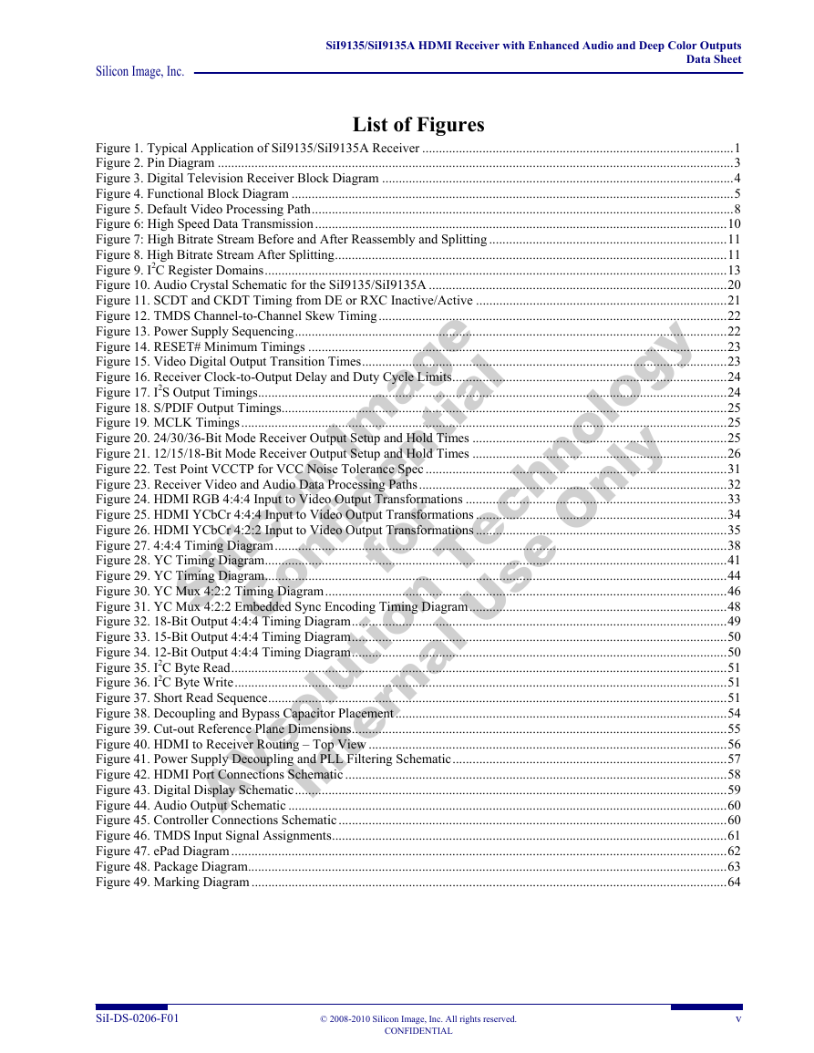
Figure 1. Typical Application of SiI9135/SiI9135A Receiver .............................................................................................1
Figure 2. Pin Diagram ..........................................................................................................................................................3
Figure 3. Digital Television Receiver Block Diagram .........................................................................................................4
Figure 4. Functional Block Diagram ....................................................................................................................................5
Figure 5. Default Video Processing Path..............................................................................................................................8
Figure 6: High Speed Data Transmission...........................................................................................................................10
Figure 7: High Bitrate Stream Before and After Reassembly and Splitting .......................................................................11
Figure 8. High Bitrate Stream After Splitting.....................................................................................................................11
Figure 9. I2C Register Domains..........................................................................................................................................13
Figure 10. Audio Crystal Schematic for the SiI9135/SiI9135A .........................................................................................20
Figure 11. SCDT and CKDT Timing from DE or RXC Inactive/Active ...........................................................................21
Figure 12. TMDS Channel-to-Channel Skew Timing........................................................................................................22
Figure 13. Power Supply Sequencing.................................................................................................................................22
Figure 14. RESET# Minimum Timings .............................................................................................................................23
Figure 15. Video Digital Output Transition Times.............................................................................................................23
Figure 16. Receiver Clock-to-Output Delay and Duty Cycle Limits..................................................................................24
Figure 17. I2S Output Timings............................................................................................................................................24
Figure 18. S/PDIF Output Timings.....................................................................................................................................25
Figure 19. MCLK Timings.................................................................................................................................................25
Figure 20. 24/30/36-Bit Mode Receiver Output Setup and Hold Times ............................................................................25
Figure 21. 12/15/18-Bit Mode Receiver Output Setup and Hold Times ............................................................................26
Figure 22. Test Point VCCTP for VCC Noise Tolerance Spec ..........................................................................................31
Figure 23. Receiver Video and Audio Data Processing Paths............................................................................................32
Figure 24. HDMI RGB 4:4:4 Input to Video Output Transformations ..............................................................................33
Figure 25. HDMI YCbCr 4:4:4 Input to Video Output Transformations ...........................................................................34
Figure 26. HDMI YCbCr 4:2:2 Input to Video Output Transformations ...........................................................................35
Figure 27. 4:4:4 Timing Diagram.......................................................................................................................................38
Figure 28. YC Timing Diagram..........................................................................................................................................41
Figure 29. YC Timing Diagram..........................................................................................................................................44
Figure 30. YC Mux 4:2:2 Timing Diagram........................................................................................................................46
Figure 31. YC Mux 4:2:2 Embedded Sync Encoding Timing Diagram.............................................................................48
Figure 32. 18-Bit Output 4:4:4 Timing Diagram................................................................................................................49
Figure 33. 15-Bit Output 4:4:4 Timing Diagram................................................................................................................50
Figure 34. 12-Bit Output 4:4:4 Timing Diagram................................................................................................................50
Figure 35. I2C Byte Read....................................................................................................................................................51
Figure 36. I2C Byte Write...................................................................................................................................................51
Figure 37. Short Read Sequence.........................................................................................................................................51
Figure 38. Decoupling and Bypass Capacitor Placement...................................................................................................54
Figure 39. Cut-out Reference Plane Dimensions................................................................................................................55
Figure 40. HDMI to Receiver Routing – Top View ...........................................................................................................56
Figure 41. Power Supply Decoupling and PLL Filtering Schematic..................................................................................57
Figure 42. HDMI Port Connections Schematic ..................................................................................................................58
Figure 43. Digital Display Schematic.................................................................................................................................59
Figure 44. Audio Output Schematic ...................................................................................................................................60
Figure 45. Controller Connections Schematic....................................................................................................................60
Figure 46. TMDS Input Signal Assignments......................................................................................................................61
Figure 47. ePad Diagram ....................................................................................................................................................62
Figure 48. Package Diagram...............................................................................................................................................63
Figure 49. Marking Diagram ..............................................................................................................................................64
Silicon Im age
AVsolution Technology
Confidential
Internal Use Only
for
SiI-DS-0206-F01
© 2008-2010 Silicon Image, Inc. All rights reserved.
CONFIDENTIAL
v
�
SiI9135/SiI9135A HDMI Receiver with Enhanced Audio and Deep Color Outputs
Data Sheet
Silicon Image, Inc.
List of Tables
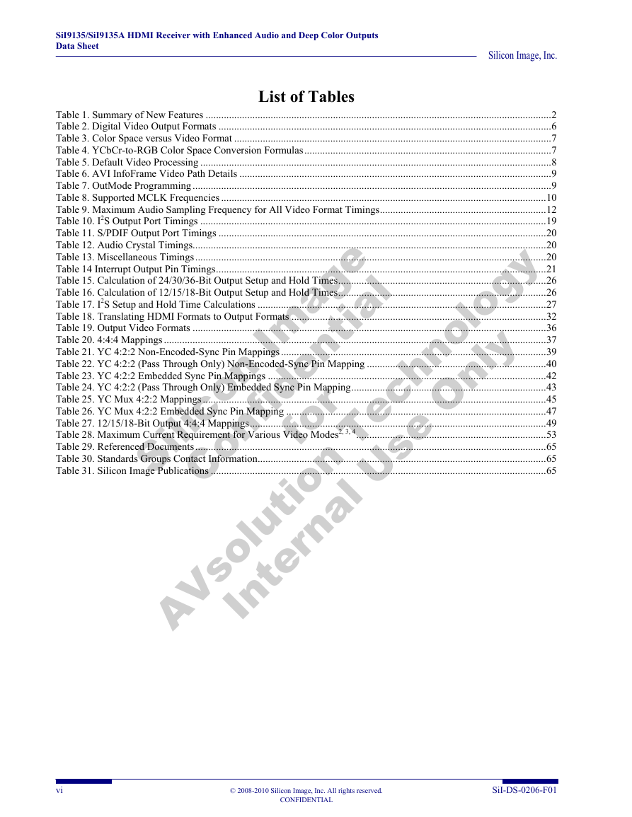
Table 1. Summary of New Features .....................................................................................................................................2
Table 2. Digital Video Output Formats ................................................................................................................................6
Table 3. Color Space versus Video Format ..........................................................................................................................7
Table 4. YCbCr-to-RGB Color Space Conversion Formulas...............................................................................................7
Table 5. Default Video Processing .......................................................................................................................................8
Table 6. AVI InfoFrame Video Path Details ........................................................................................................................9
Table 7. OutMode Programming ..........................................................................................................................................9
Table 8. Supported MCLK Frequencies .............................................................................................................................10
Table 9. Maximum Audio Sampling Frequency for All Video Format Timings................................................................12
Table 10. I2S Output Port Timings .....................................................................................................................................19
Table 11. S/PDIF Output Port Timings ..............................................................................................................................20
Table 12. Audio Crystal Timings........................................................................................................................................20
Table 13. Miscellaneous Timings.......................................................................................................................................20
Table 14 Interrupt Output Pin Timings...............................................................................................................................21
Table 15. Calculation of 24/30/36-Bit Output Setup and Hold Times................................................................................26
Table 16. Calculation of 12/15/18-Bit Output Setup and Hold Times................................................................................26
Table 17. I2S Setup and Hold Time Calculations ...............................................................................................................27
Table 18. Translating HDMI Formats to Output Formats ..................................................................................................32
Table 19. Output Video Formats ........................................................................................................................................36
Table 20. 4:4:4 Mappings ...................................................................................................................................................37
Table 21. YC 4:2:2 Non-Encoded-Sync Pin Mappings......................................................................................................39
Table 22. YC 4:2:2 (Pass Through Only) Non-Encoded-Sync Pin Mapping .....................................................................40
Table 23. YC 4:2:2 Embedded Sync Pin Mappings ...........................................................................................................42
Table 24. YC 4:2:2 (Pass Through Only) Embedded Sync Pin Mapping...........................................................................43
Table 25. YC Mux 4:2:2 Mappings ....................................................................................................................................45
Table 26. YC Mux 4:2:2 Embedded Sync Pin Mapping ....................................................................................................47
Table 27. 12/15/18-Bit Output 4:4:4 Mappings..................................................................................................................49
Table 28. Maximum Current Requirement for Various Video Modes2, 3, 4.........................................................................53
Table 29. Referenced Documents.......................................................................................................................................65
Table 30. Standards Groups Contact Information...............................................................................................................65
Table 31. Silicon Image Publications .................................................................................................................................65
Silicon Im age
AVsolution Technology
Confidential
Internal Use Only
for
vi
© 2008-2010 Silicon Image, Inc. All rights reserved.
CONFIDENTIAL
SiI-DS-0206-F01
�
SiI9135/SiI9135A HDMI Receiver with Enhanced Audio and Deep Color Outputs
Data Sheet
Digital Video Interface
• Flexible support for many different standard- and
high-definition video formats (36-bit RGB /
YCbCr 4:4:4, 16/20/24-bit YCbCr 4:2:2, 8/10/12-
bit YCbCr 4:2:2 (ITU BT.656))
12/15/18-bit Digital Multimedia Output (DMO)
RGB/YCbCr 4:4:4 (clocked with rising and falling
edges)
• Color Space Conversion for both RGB-to-YCbCr
and YCbCr-to-RGB (both 601 and 709)
• True 12-bit accurate data using 14-bit processing
• Auto video mode configuration simplifies system
•
firmware design
.
Introduction
The SiI9135/SiI9135A HDMI Receiver with Enhanced
Audio and Deep Color Outputs is a second-generation
dual-input High Definition Multimedia Interface (HDMI)
receiver. It is software-compatible with the SiI9133
receiver, but adds audio support for DTS-HD and Dolby
TrueHD. Digital televisions that can display 10- or 12-bit
color depth can now provide the highest quality protected
digital audio and video over a single cable. The SiI9135
and SiI9135A devices, which are functionally identical,
can receive Deep Color video up to 12-bit, 1080p @ 60
Hz. Backward compatibility with the DVI 1.0
specification allows HDMI systems to connect to existing
DVI 1.0 hosts, such as HD set-top boxes and PCs. Silicon
Image HDMI receivers use the latest generation Transition
Minimized Differential Signaling (TMDS) core
technology that runs at 25–225 MHz.
The chip comes pre-programmed with High-bandwidth
Digital Content Protection (HDCP) keys for receiving
protected audio and video content. This set of keys
simplifies the manufacturing process and lowers costs
while providing the highest level of HDCP key
security.
The SiI9135/SiI9135A receiver can send and receive up
to eight channels of uncompressed digital audio at
192 kHz and 2-channel digital audio up to 192 kHz.
Compressed streams are also supported through either
the S/PDIF port or over I2S for DTS-HD and Dolby
TrueHD. An industry-standard I2S port allows direct
connection to low-cost audio DACs at up to 192 kHz. An
S/PDIF port supports up to 192 kHz audio. The device
supports Super Audio Compact Disc (SACD) and
provides Direct Stream Digital (DSD) ports that support
44.1 and 88.2-kHz one-bit audio.
A low-power standby feature of the SiI9135/SiI9135A
receiver enables flexible power management.
Silicon Im age
AVsolution Technology
Confidential
Internal Use Only
for
Package
•
downstream devices)
Digital Audio Interface
• DTS-HD and Dolby TrueHD high bit rate audio
• Four I2S inputs accept Dolby Digital, DVD-Audio
input (2-channel 192 kHz and 8-channel 192 kHz)
• S/PDIF input supports PCM, Dolby Digital, DTS
digital audio transmission (32–192 kHz Fs sample
rate)
IEC60958 or IEC61937 compatible
•
• Flexible, programmable I2S channel mapping
HDCP Decryption
• Pre-programmed HDCP keys provide the highest
level of key security, simplify manufacturing, and
lower cost
• Full support for HDCP repeaters (up to 16 attached
20 mm x 20 mm 144-pin TQFP package with ePad™
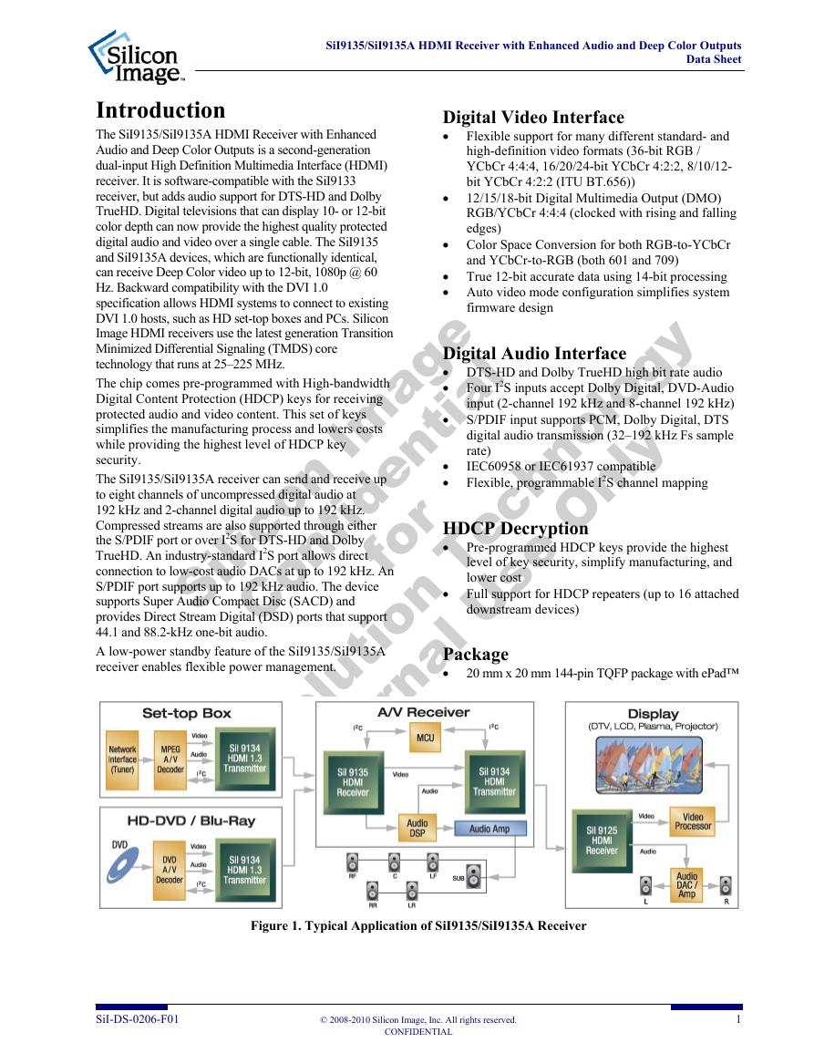
Figure 1. Typical Application of SiI9135/SiI9135A Receiver
SiI-DS-0206-F01
© 2008-2010 Silicon Image, Inc. All rights reserved.
CONFIDENTIAL
1
�
SiI9135/SiI9135A HDMI Receiver with Enhanced Audio and Deep Color Outputs
Data Sheet
System Applications
The SiI9135/SiI9135A receiver is designed for AV receivers that require support for HDMI Deep Color and the latest
audio technologies: DTS-HD and Dolby TrueHD. The receiver allows receiving 10/12-bit color depth up to 1080p
resolutions. A single device provides two HDMI input ports. The video output goes to a video processor or HDMI
transmitter. Besides DTS-HD and Dolby TrueHD, the device supports full surround sound audio including DVD-Audio
and SACD. The audio output can go directly to an audio DAC or an audio digital signal processor for further processing.
Silicon Image, Inc.
SiI9033
8-bit
165 MHz
225 MHz
225 MHz
165 MHz.
165 MHz.
165 MHz.
8/10/12-bit
8/10/12-bit
SiI9133
SiI9135/SiI9135A
2
2
1
2
2
1
Digital Video Output Ports
TMDS Input Ports
Color Depth
DDC Input Ports
Comparing the SiI9135/SiI9135A Receiver with the SiI9033 and SiI9133
Receivers
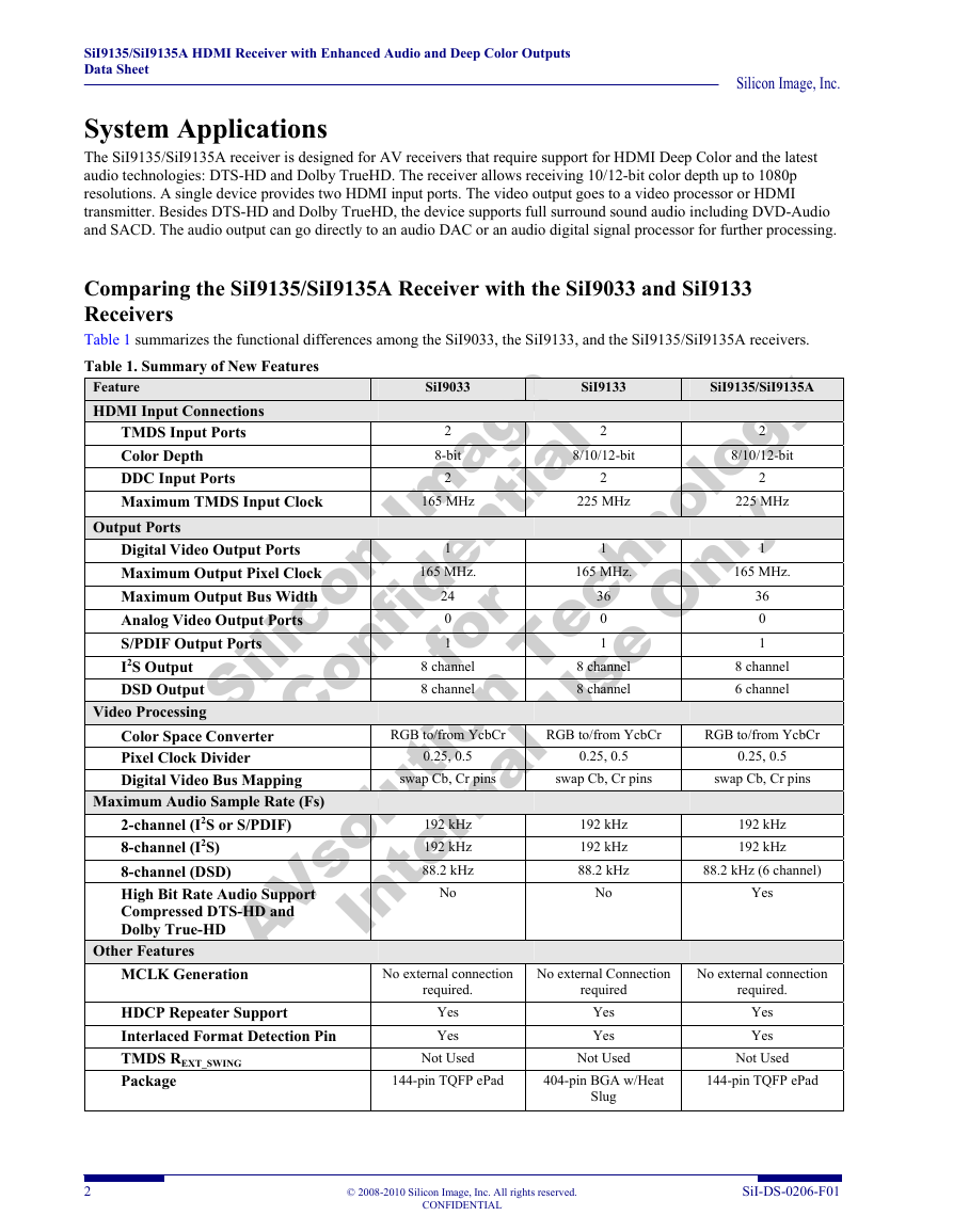
Table 1 summarizes the functional differences among the SiI9033, the SiI9133, and the SiI9135/SiI9135A receivers.
Table 1. Summary of New Features
Feature
HDMI Input Connections
Maximum TMDS Input Clock
Output Ports
Maximum Output Pixel Clock
Maximum Output Bus Width
Analog Video Output Ports
S/PDIF Output Ports
I2S Output
DSD Output
Video Processing
Maximum Audio Sample Rate (Fs)
High Bit Rate Audio Support
Other Features
MCLK Generation
Silicon Im age
AVsolution Technology
Confidential
Internal Use Only
for
Color Space Converter
Pixel Clock Divider
Digital Video Bus Mapping
2-channel (I2S or S/PDIF)
8-channel (I2S)
8-channel (DSD)
Compressed DTS-HD and
Dolby True-HD
192 kHz
192 kHz
88.2 kHz
192 kHz
192 kHz
88.2 kHz
No external Connection
No external connection
8 channel
8 channel
8 channel
8 channel
8 channel
6 channel
192 kHz
192 kHz
swap Cb, Cr pins
swap Cb, Cr pins
swap Cb, Cr pins
2
2
1
36
0
1
RGB to/from YcbCr
RGB to/from YcbCr
RGB to/from YcbCr
24
0
1
0.25, 0.5
0.25, 0.5
36
0
1
88.2 kHz (6 channel)
Yes
No
No
required.
required
No external connection
required.
0.25, 0.5
HDCP Repeater Support
Interlaced Format Detection Pin
TMDS REXT_SWING
Package
Yes
Yes
Not Used
144-pin TQFP ePad
Yes
Yes
Not Used
404-pin BGA w/Heat
Slug
Yes
Yes
Not Used
144-pin TQFP ePad
2
© 2008-2010 Silicon Image, Inc. All rights reserved.
CONFIDENTIAL
SiI-DS-0206-F01
�


 2023年江西萍乡中考道德与法治真题及答案.doc
 2012年重庆南川中考生物真题及答案.doc
 2013年江西师范大学地理学综合及文艺理论基础考研真题.doc
 2020年四川甘孜小升初语文真题及答案I卷.doc
 2020年注册岩土工程师专业基础考试真题及答案.doc
 2023-2024学年福建省厦门市九年级上学期数学月考试题及答案.doc
 2021-2022学年辽宁省沈阳市大东区九年级上学期语文期末试题及答案.doc
 2022-2023学年北京东城区初三第一学期物理期末试卷及答案.doc
 2018上半年江西教师资格初中地理学科知识与教学能力真题及答案.doc
 2012年河北国家公务员申论考试真题及答案-省级.doc
 2020-2021学年江苏省扬州市江都区邵樊片九年级上学期数学第一次质量检测试题及答案.doc
 2022下半年黑龙江教师资格证中学综合素质真题及答案.doc