SOLOMON SYSTECH
SEMICONDUCTOR TECHNICAL DATA
SSD1315
Advance Information
128 x 64 Dot Matrix
OLED/PLED Segment/Common Driver with Controller
This document contains information on a new product. Specifications and information herein are subject to change
without notice.
http://www.solomon-systech.com
SSD1315
Copyright 2016 Solomon Systech Limited
Rev 1.0
P 1/36
Dec 2016
�
Appendix: IC Revision history of SSD1315 Specification
Version
1.0
1st Release
Change Items
Effective Date
05-Jan-17
Solomon Systech
Dec 2016
P 2/36
Rev 1.0
SSD1315
�
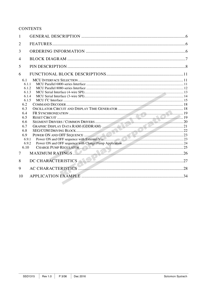
CONTENTS
1
2
3
4
5
6
7
8
9
GENERAL DESCRIPTION ................................................................................................ 6
FEATURES ........................................................................................................................... 6
ORDERING INFORMATION ............................................................................................ 6
BLOCK DIAGRAM ............................................................................................................. 7
PIN DESCRIPTION ............................................................................................................. 8
FUNCTIONAL BLOCK DESCRIPTIONS ....................................................................... 11
6.1 MCU INTERFACE SELECTION ......................................................................................................... 11
6.1.1 MCU Parallel 6800-series Interface .......................................................................................................... 11
6.1.2 MCU Parallel 8080-series Interface .......................................................................................................... 12
6.1.3 MCU Serial Interface (4-wire SPI) ............................................................................................................ 13
6.1.4 MCU Serial Interface (3-wire SPI) ............................................................................................................ 14
6.1.5 MCU I2C Interface ................................................................................................................................... 15
6.2 COMMAND DECODER ..................................................................................................................... 18
6.3 OSCILLATOR CIRCUIT AND DISPLAY TIME GENERATOR ................................................................. 18
6.4
FR SYNCHRONIZATION .................................................................................................................. 19
6.5 RESET CIRCUIT .............................................................................................................................. 19
6.6
SEGMENT DRIVERS / COMMON DRIVERS ........................................................................................ 20
6.7 GRAPHIC DISPLAY DATA RAM (GDDRAM) ................................................................................. 21
6.8
SEG/COM DRIVING BLOCK ........................................................................................................... 22
POWER ON AND OFF SEQUENCE ................................................................................................... 23
6.9
Power ON and OFF sequence with External VCC....................................................................................... 23
6.9.1
Power ON and OFF sequence with Charge Pump Application ................................................................... 24
6.9.2
6.10
CHARGE PUMP REGULATOR ....................................................................................................... 25
MAXIMUM RATINGS ...................................................................................................... 26
DC CHARACTERISTICS ................................................................................................. 27
AC CHARACTERISTICS ................................................................................................. 28
10 APPLICATION EXAMPLE .............................................................................................. 34
SSD1315
Rev 1.0
P 3/36
Dec 2016
Solomon Systech
�
TABLES
Table 3-1: Ordering Information .................................................................................................................................... 6
Table 5-1: Pin Description ............................................................................................................................................. 8
Table 5-2: Bus Interface selection .................................................................................................................................. 8
Table 6-1: MCU interface assignment under different bus interface mode .................................................................... 11
Table 6-2: Control pins of 6800 interface ..................................................................................................................... 11
Table 6-3: Control pins of 8080 interface ..................................................................................................................... 13
Table 6-4: Control pins of 4-wire Serial interface ......................................................................................................... 13
Table 6-5: Control pins of 3-wire Serial interface ......................................................................................................... 14
Table 7-1: Maximum Ratings ...................................................................................................................................... 26
Table 8-1: DC Characteristics ...................................................................................................................................... 27
Table 9-1: AC Characteristics ...................................................................................................................................... 28
Table 9-2: 6800-Series MCU Parallel Interface Timing Characteristics ........................................................................ 29
Table 9-3: 8080-Series MCU Parallel Interface Timing Characteristics ........................................................................ 30
Table 9-4: Serial Interface Timing Characteristics (4-wire SPI) .................................................................................... 31
Table 9-5: Serial Interface Timing Characteristics (3-wire SPI) .................................................................................... 32
Table 9-6: I2C Interface Timing Characteristics ........................................................................................................... 33
Solomon Systech
Dec 2016
P 4/36
Rev 1.0
SSD1315
�
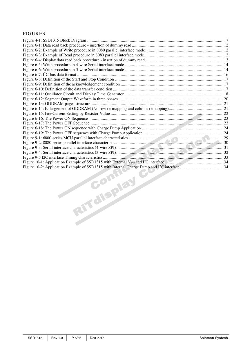
FIGURES
Figure 4-1: SSD1315 Block Diagram ............................................................................................................................ 7
Figure 6-1: Data read back procedure - insertion of dummy read .................................................................................. 12
Figure 6-2: Example of Write procedure in 8080 parallel interface mode ...................................................................... 12
Figure 6-3: Example of Read procedure in 8080 parallel interface mode....................................................................... 12
Figure 6-4: Display data read back procedure - insertion of dummy read ...................................................................... 13
Figure 6-5: Write procedure in 4-wire Serial interface mode ........................................................................................ 14
Figure 6-6: Write procedure in 3-wire Serial interface mode ........................................................................................ 14
Figure 6-7: I2C-bus data format ................................................................................................................................... 16
Figure 6-8: Definition of the Start and Stop Condition ................................................................................................. 17
Figure 6-9: Definition of the acknowledgement condition ............................................................................................ 17
Figure 6-10: Definition of the data transfer condition ................................................................................................... 17
Figure 6-11: Oscillator Circuit and Display Time Generator ......................................................................................... 18
Figure 6-12: Segment Output Waveform in three phases .............................................................................................. 20
Figure 6-13: GDDRAM pages structure ....................................................................................................................... 21
Figure 6-14: Enlargement of GDDRAM (No row re-mapping and column-remapping)................................................. 21
Figure 6-15: IREF Current Setting by Resistor Value ..................................................................................................... 22
Figure 6-16: The Power ON Sequence ......................................................................................................................... 23
Figure 6-17: The Power OFF Sequence ....................................................................................................................... 23
Figure 6-18: The Power ON sequence with Charge Pump Application ......................................................................... 24
Figure 6-19: The Power OFF sequence with Charge Pump Application ........................................................................ 24
Figure 9-1: 6800-series MCU parallel interface characteristics ..................................................................................... 29
Figure 9-2: 8080-series parallel interface characteristics ............................................................................................... 30
Figure 9-3: Serial interface characteristics (4-wire SPI) ................................................................................................ 31
Figure 9-4: Serial interface characteristics (3-wire SPI) ................................................................................................ 32
Figure 9-5 I2C interface Timing characteristics ............................................................................................................ 33
Figure 10-1: Application Example of SSD1315 with External VCC and I2C interface .................................................... 34
Figure 10-2: Application Example of SSD1315 with Internal Charge Pump and I2C interface ....................................... 34
SSD1315
Rev 1.0
P 5/36
Dec 2016
Solomon Systech
�
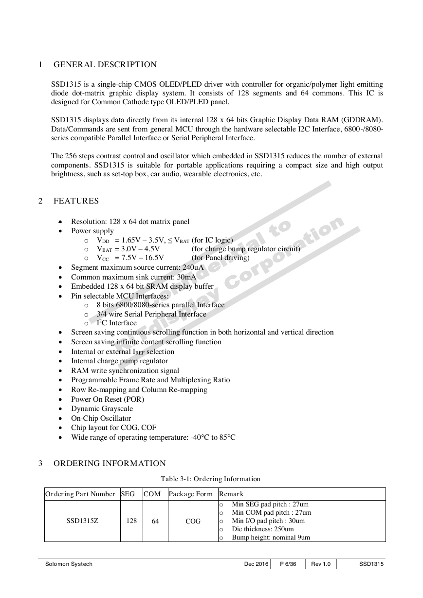
1 GENERAL DESCRIPTION
SSD1315 is a single-chip CMOS OLED/PLED driver with controller for organic/polymer light emitting
diode dot-matrix graphic display system. It consists of 128 segments and 64 commons. This IC is
designed for Common Cathode type OLED/PLED panel.
SSD1315 displays data directly from its internal 128 x 64 bits Graphic Display Data RAM (GDDRAM).
Data/Commands are sent from general MCU through the hardware selectable I2C Interface, 6800-/8080-
series compatible Parallel Interface or Serial Peripheral Interface.
The 256 steps contrast control and oscillator which embedded in SSD1315 reduces the number of external
components. SSD1315 is suitable for portable applications requiring a compact size and high output
brightness, such as set-top box, car audio, wearable electronics, etc.
2 FEATURES
Resolution: 128 x 64 dot matrix panel
Power supply
o VDD = 1.65V – 3.5V, ≤ VBAT (for IC logic)
o VBAT = 3.0V – 4.5V
o VCC = 7.5V – 16.5V (for Panel driving)
(for charge bump regulator circuit)
Segment maximum source current: 240uA
Common maximum sink current: 30mA
Embedded 128 x 64 bit SRAM display buffer
Pin selectable MCU Interfaces:
o 8 bits 6800/8080-series parallel Interface
o 3/4 wire Serial Peripheral Interface
o
I2C Interface
Internal or external IREF selection
Internal charge pump regulator
Screen saving continuous scrolling function in both horizontal and vertical direction
Screen saving infinite content scrolling function
RAM write synchronization signal
Programmable Frame Rate and Multiplexing Ratio
Row Re-mapping and Column Re-mapping
Power On Reset (POR)
Dynamic Grayscale
On-Chip Oscillator
Chip layout for COG, COF
Wide range of operating temperature: -40C to 85C
3 ORDERING INFORMATION
Ordering Part Number SEG COM Package Form Remark
Table 3-1: Ordering Information
SSD1315Z
128
64
COG
o Min SEG pad pitch : 27um
o Min COM pad pitch : 27um
o Min I/O pad pitch : 30um
o Die thickness: 250um
o Bump height: nominal 9um
Solomon Systech
Dec 2016
P 6/36
Rev 1.0
SSD1315
�
4 BLOCK DIAGRAM
VCC
C1N
C1P
C2N
C2P
RES#
CS#
D/C#
E(RD#)
R/W# (WR#)
BS0
BS1
BS2
LS
D7
D6
D5
D4
D3
D2
D1
D0
VDD
VSS
VLSS
BGGND
Figure 4-1: SSD1315 Block Diagram
VBAT
Charge-pump
e
c
a
f
r
e
t
n
I
U
C
M
M
A
R
D
D
G
d
n
a
m
m
o
C
r
e
d
o
c
e
D
L
C
r
o
t
a
l
l
i
c
s
O
r
o
t
a
r
e
n
e
G
y
a
l
p
s
i
D
g
n
i
m
T
i
k
c
o
l
B
g
n
i
v
i
r
D
M
O
C
G
E
S
/
S
L
C
R
F
F
E
R
I
H
M
O
C
V
s
r
e
v
i
r
D
n
o
m
m
o
C
r
e
v
i
r
D
t
n
e
m
g
e
S
s
r
e
v
i
r
D
n
o
m
m
o
C
Com63
Com62
.
.
.
.
.
.
.
.
.
.
.
.
Com31
Com32
Seg127
Seg126
.
.
.
.
.
Seg1
Seg0
Com0
Com1
.
.
.
.
.
.
.
.
.
.
.
Com30
Com31
.
.
.
.
.
.
.
.
.
.
.
.
.
.
.
.
.
.
.
.
.
.
.
.
.
.
.
.
.
.
.
.
.
.
.
.
SSD1315
Rev 1.0
P 7/36
Dec 2016
Solomon Systech
�
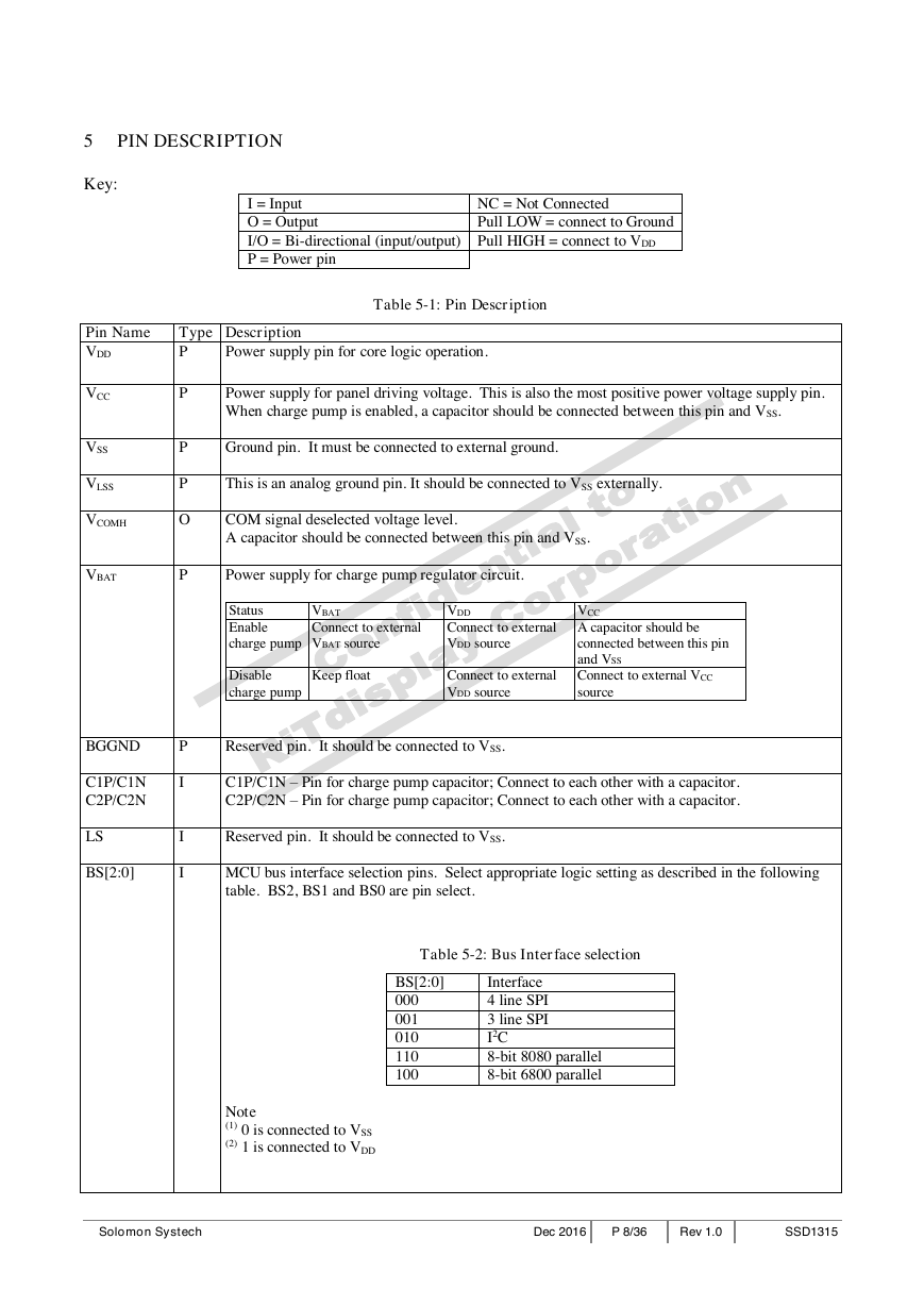
5 PIN DESCRIPTION
Key:
I = Input
O = Output
I/O = Bi-directional (input/output) Pull HIGH = connect to VDD
P = Power pin
NC = Not Connected
Pull LOW = connect to Ground
Pin Name
VDD
Type Description
P
Power supply pin for core logic operation.
Table 5-1: Pin Description
VCC
VSS
VLSS
VCOMH
VBAT
BGGND
C1P/C1N
C2P/C2N
LS
BS[2:0]
P
P
P
O
P
P
I
I
I
Power supply for panel driving voltage. This is also the most positive power voltage supply pin.
When charge pump is enabled, a capacitor should be connected between this pin and VSS.
Ground pin. It must be connected to external ground.
This is an analog ground pin. It should be connected to VSS externally.
COM signal deselected voltage level.
A capacitor should be connected between this pin and VSS.
Power supply for charge pump regulator circuit.
Status
Enable
charge pump
VBAT
Connect to external
VBAT source
VDD
Connect to external
VDD source
VCC
A capacitor should be
connected between this pin
and VSS
Connect to external VCC
source
Keep float
Connect to external
VDD source
Disable
charge pump
Reserved pin. It should be connected to VSS.
C1P/C1N – Pin for charge pump capacitor; Connect to each other with a capacitor.
C2P/C2N – Pin for charge pump capacitor; Connect to each other with a capacitor.
Reserved pin. It should be connected to VSS.
MCU bus interface selection pins. Select appropriate logic setting as described in the following
table. BS2, BS1 and BS0 are pin select.
Table 5-2: Bus Interface selection
BS[2:0]
000
001
010
110
100
Interface
4 line SPI
3 line SPI
I2C
8-bit 8080 parallel
8-bit 6800 parallel
Note
(1) 0 is connected to VSS
(2) 1 is connected to VDD
Solomon Systech
Dec 2016
P 8/36
Rev 1.0
SSD1315
�




 2023年江西萍乡中考道德与法治真题及答案.doc
 2012年重庆南川中考生物真题及答案.doc
 2013年江西师范大学地理学综合及文艺理论基础考研真题.doc
 2020年四川甘孜小升初语文真题及答案I卷.doc
 2020年注册岩土工程师专业基础考试真题及答案.doc
 2023-2024学年福建省厦门市九年级上学期数学月考试题及答案.doc
 2021-2022学年辽宁省沈阳市大东区九年级上学期语文期末试题及答案.doc
 2022-2023学年北京东城区初三第一学期物理期末试卷及答案.doc
 2018上半年江西教师资格初中地理学科知识与教学能力真题及答案.doc
 2012年河北国家公务员申论考试真题及答案-省级.doc
 2020-2021学年江苏省扬州市江都区邵樊片九年级上学期数学第一次质量检测试题及答案.doc
 2022下半年黑龙江教师资格证中学综合素质真题及答案.doc