FM-H6594.tex
8/5/2007
12: 31
Page xv
Preface to the second edition
This second, long (over)due, edition presents a major extension and restructur-
ing of the initial two volumes edition, based on objective as well as subjective
elements.
The first group of arguments is related to numerous requests we have received over
the years after the initial publication, for enhancing the didactic structure of the two
volumes in order to respond to the development of CFD courses, starting often now
at an advanced undergraduate level.
We decided therefore to adapt the first volume, which was oriented at the fundamen-
tals of numerical discretizations, toward a more self-contained and student-oriented
first course material for an introduction to CFD. This has led to the following changes
in this second edition:
• We have focused on a presentation of the essential components of a simulation
system, at an introductory level to CFD, having in mind students who come in
contact with the world of CFD for the first time. The objective being to make the
student aware of the main steps required by setting up a numerical simulation,
and the various implications as well as the variety of options available. This
will cover Chapters 1–10, while Chapters 11 and 12 are dedicated to the first
applications of the general methodology to inviscid simple flows in Chapter 11
and to 2D incompressible, viscous flows in Chapter 12.
• Several chapters are subdivided into two parts: an introductory level written for
a first introductory course to CFD and a second, more advanced part, which is
more suitable for a graduate and more advanced CFD course. We hope that by
putting together the introductory presentation and the more advanced topics, the
student will be stimulated by the first approach and his/her curiosity for the more
advanced level, which is closer to the practical world of CFD, will be aroused.
We also hope by this way to avoid frightening off the student who would be
totally new to CFD, by a too ‘brutal’ contact with an approach that might appear
as too abstract and mathematical.
• Each chapter is introduced by a section describing the ‘Objectives and guidelines
to this Chapter’, and terminates by a section on ‘Conclusions and main topics
to remember’, allowing the instructor or the student to establish his or her guide
through the selected source material.
• The chapter on finite differences has been extended with additional considera-
tions given to discretizations formulas on non-uniform grids.
• The chapters on finite element and finite volume methods have been merged,
shifting the finite element description to the ‘advanced’ level, into Chapter 5 of
this volume.
• A new Chapter 6 has been added devoted to an overview of various grids used
in practice, including some recommendations related to grid quality.
xv
�
FM-H6594.tex
8/5/2007
12: 31
Page xvi
xvi Preface
• Chapters 7 and 8 of the first edition, devoted to the analysis of numerical schemes
for consistency and stability have been merged and simplified, forming the new
Chapter 7.
• Chapter 9 of the first edition has been largely reorganized, simplified and
extended with new material related to general scheme properties, in particu-
lar the extremely important concept of monotonicity and the methodologies
required to suppress numerical oscillations with higher order schemes, with the
introduction of limiters. This is found in Chapter 8 of this volume.
• The former Chapters 10 and 11 have been merged in the new Chapter 9, devoted
to the time integration schemes and to the general methodologies resulting from
the combination of a selected space discretization with a separate time integration
method.
• Parts of the second volume have been transferred to the first volume; in partic-
ular sections on potential flows (presented in Chapter 11) and two-dimensional
viscous flows in Chapter 12. This should allow the student already to come in
contact, at this introductory CFD level, with initial applications of fluid flow
simulations.
• The number of problems has been increased and complete solution manuals will
be made available to the instructors. Also a computer program for the numerical
solutions of simple 1D convection and convection–diffusion equations, with a
large variety of schemes and test cases can be made available to the instructors,
for use in classes and exercises sessions. The objective of this option is to provide
a tool allowing the students to develop their own ‘feeling’ and experience with
various schemes, including assessment of the different types and level of errors
generated by the combination of schemes and test cases. Many of the figures in
the two volumes have been generated with these programs.
The second group of elements is connected to the considerable evolution and exten-
sion of Computational Fluid Dynamics (CFD) since the first publication of these
books. CFD is now an integral part of any fluid-related research and industrial appli-
cation, and is progressively reaching a mature stage. Its evolution, since the initial
publication of this book, has been marked by significant advancements, which we
feel have to be covered, at least partly, in order to provide the reader with a reliable
and up-to-date introduction and account of modern CFD. This relates in particular to:
• Major developments of schemes and codes based on unstructured grids, which
are today the ‘standard’, particularly with most of the commercial CFD packages,
as unstructured codes take advantage of the availability of nearly automatic grid
generation tools for complex geometries.
• Advances in high-resolution algorithms, which have provided a deep insight in
the general properties of numerical schemes, leading to a unified and elegant
approach, where concepts of accuracy, stability, monotonicity can be defined
and applied to any type of equation.
• Major developments in turbulence modeling,
including Direct Numerical
Simulations (DNS) and Large Eddy Simulations (LES).
• Applications of full 3D Navier–Stokes simulations to an extreme variety of com-
plex industrial, environmental, bio-medical and other disciplines, where fluids
�
FM-H6594.tex
8/5/2007
12: 31
Page xvii
Preface xvii
play a role in their properties and evolution. This has led to a considerable overall
experience accumulated over the last decade, on schemes and models.
• The awareness of the importance of verification and validation of CFD codes and
the development of related methodologies. This has given rise to the definition
and evaluation of families of test cases including the related quality assessment
issues.
• The wide availability of commercial CFD codes, which are increasingly being
used as teaching tools, to support the understanding of fluid mechanics and/or
to generate simple flow simulations. This puts a strong emphasis on the need for
educating students in the use of codes and providing them with an awareness
of possible inaccuracies, sources of errors, grid and modeling effects and, more
generally, with some global Best Practice Guidelines.
Many of these topics will be found in the second edition of Volume II.
I have benefited from the spontaneous input from many colleagues and students,
who have been kind enough to send me notices about misprints in text and in formulas,
helping hereby in improving the quality of the books and correcting errors. I am very
grateful to all of them.
I also have to thank many of my students and researchers, who have contributed
at various levels; in particular: Dr. Zhu Zong–Wen for the many problem solutions;
Cristian Dinescu for various corrections. Benoit Tartinville and Dr. Sergey Smirnov
have contributed largely to the calculations and derivations in Chapters 11 and 12.
Brussels, December 2006
�
FM-H6594.tex
8/5/2007
12: 31
Page xviii
Nomenclature
a
A
c
cp
cv
D
e
e
ex,ey,ez
E
E
f
fe
F ( f , g, h)
g
G
h
H
I
J
k
k
M
n
n
p
P
Pr
q
qH
Q
r
R
Re
s
S
S
t
T
u
U
convection velocity or wave speed
Jacobian of flux function
speed of sound
specific heat at constant pressure
specific heat at constant volume
first derivative operator
internal energy per unit mass
vector (column matrix) of solution errors
unit vectors along the x, y, z directions
total energy per unit volume
finite difference displacement (shift) operator
flux function
external force vector
flux vector with components f , g, h
gravity acceleration
amplification factor/matrix
enthalpy per unit mass
total enthalpy
rothalpy
Jacobian
coefficient of thermal conductivity
wave number
Mach number
normal distance
normal vector
pressure
convergence or conditioning operator
Prandtl number
non homogeneous term
heat source
source term; matrix of non homogeneous terms
gas constant per unit mass
residual of iterative scheme
Reynolds number
entropy per unit mass
space discretization operator
surface vector
time
temperature
dependent variable
vector (column matrix) of dependent variables
xviii
�
FM-H6594.tex
8/5/2007
12: 31
Page xix
Nomenclature xix
vector of conservative variables; velocity
velocity vector with components u, v, w
eigenvectors of space discretization matrix
relative velocity
weight function
cartesian coordinates
amplification factor of time integration scheme
diffusivity coefficient
dimensionless diffusion coefficient β= α�t/�x, also called Von
Neumann number
specific heat ratio
circulation; boundary of domain �
central-difference operator
forward and backward difference operators
Laplace operator
time step
variation of solution U between levels n+ 1 and n
spatial mesh size in x and y directions
error of numerical solution
turbulence dissipation rate
dissipation or diffusion error
dispersion error
vorticity vector
parameter controlling type of difference scheme
wave-number vector; wave propagation direction
eigenvalue of amplification matrix
coefficient of dynamic viscosity
averaging difference operator
real part of amplification matrix
imaginary part of amplification matrix
density; spectral radius
Courant number
shear stress tensor
stress tensor
kinematic viscosity
velocity potential; phase angle in Von Neumann analysis
phase angle of amplification factor
time frequency of plane wave; overrelaxation parameters
eigenvalue of space discretization matrix; volume
U
v (u, v, w)
V
w
W
x, y, z
z
α
β
−
, δ
γ
�
δ
+
δ
�
�t
�U
�x, �y
ε
εv
εD
εφ
ζ
κ
θ
λ
µ
µ
ξ
η
ρ
σ
σ
τ
ν
φ
�
ω
�
Subscripts
e
i, j
I, J
J
external variable
mesh point locations in x, y directions
nodal point index
eigenvalue number
�
FM-H6594.tex
8/5/2007
12: 31
Page xx
xx Nomenclature
min
max
n
o
v
x, y, z
∞
minimum
maximum
normal or normal component
stagnation values
viscous term
components in x, y, z directions; partial differentiation with respect
to x, y, z
freestream value
Superscripts
n
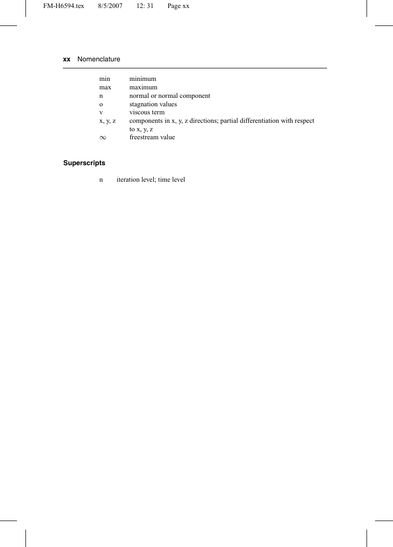
iteration level; time level
�
Intro-H6594.tex
9/5/2007
11: 42
Page 1
Introduction: An Initial Guide to CFD
and to this Volume
Computational Fluid Dynamics, known today as CFD, is defined as the set of
methodologies that enable the computer to provide us with a numerical simulation of
fluid flows.
We use the word ‘simulation’ to indicate that we use the computer to solve numer-
ically the laws that govern the movement of fluids, in or around a material system,
where its geometry is also modeled on the computer. Hence, the whole system is
transformed into a ‘virtual’ environment or virtual product. This can be opposed to
an experimental investigation, characterized by a material model or prototype of the
system, such as an aircraft or car model in a wind tunnel, or when measuring the flow
properties in a prototype of an engine.
This terminology is also referring to the fact that we can visualize the whole system
and its behavior, through computer visualization tools, with amazing levels of realism,
as you certainly have experienced through the powerful computer games and/or movie
animations, that provide a fascinating level of high-fidelity rendering. Hence the
complete system, such as a car, an airplane, a block of buildings, etc. can be ‘seen’
on a computer, before any part is ever constructed.
I.1 THE POSITION OF CFD IN THE WORLD OF VIRTUAL PROTOTYPING
To situate the role and importance of CFD in our contemporary technological world, it
might be of interest to take you down the road to the global world of Computer-Assisted
Engineering or CAE. CAE refers to the ensemble of simulation tools that support
the work of the engineer between the initial design phase and the final definition of
the manufacturing process. The industrial production process is indeed subjected to
an accelerated evolution toward the computerization of the whole production cycle,
using various software tools.
The most important of them are: Computer-Assisted Design (CAD), Computer-
Assisted Engineering (CAE) and Computer-Assisted Manufacturing (CAM) soft-
ware. The CAD/CAE/CAM software systems form the basis for the different phases
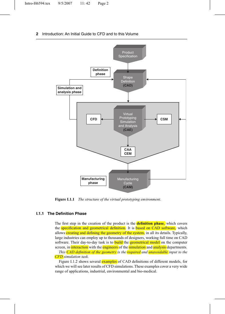
of the virtual prototyping environment as shown in Figure I.1.1.
This chart presents the different components of a computer-oriented environment,
as used in industry to create, or modify toward better properties, a product. This
product can be a single component such as a cooling jacket in a car engine, formed
by a certain number of circular curved pipes, down to a complete car. In all cases the
succession of steps and the related software tools are used in very much similar ways,
the difference being the degree of complexity to which these tools are applied.
1
�
Intro-H6594.tex
9/5/2007
11: 42
Page 2
2 Introduction: An Initial Guide to CFD and to this Volume
Simulation and
analysis phase
Definition
phase
CFD
Product
Specification
Shape
Definition
(CAD)
Virtual
Prototyping
Simulation
and Analysis
(CAE)
CAA
CEM
CSM
Manufacturing
phase
Manufacturing
Cycle
(CAM)
Figure I.1.1 The structure of the virtual prototyping environment.
I.1.1 The Definition Phase
The first step in the creation of the product is the definition phase, which covers
the specification and geometrical definition. It is based on CAD software, which
allows creating and defining the geometry of the system, in all its details. Typically,
large industries can employ up to thousands of designers, working full time on CAD
software. Their day-to-day task is to build the geometrical model on the computer
screen, in interaction with the engineers of the simulation and analysis departments.
This CAD definition of the geometry is the required and unavoidable input to the
CFD simulation task.
Figure I.1.2 shows several examples of CAD definitions of different models, for
which we will see later results of CFD simulations. These examples cover a very wide
range of applications, industrial, environmental and bio-medical.
�




 2023年江西萍乡中考道德与法治真题及答案.doc
 2012年重庆南川中考生物真题及答案.doc
 2013年江西师范大学地理学综合及文艺理论基础考研真题.doc
 2020年四川甘孜小升初语文真题及答案I卷.doc
 2020年注册岩土工程师专业基础考试真题及答案.doc
 2023-2024学年福建省厦门市九年级上学期数学月考试题及答案.doc
 2021-2022学年辽宁省沈阳市大东区九年级上学期语文期末试题及答案.doc
 2022-2023学年北京东城区初三第一学期物理期末试卷及答案.doc
 2018上半年江西教师资格初中地理学科知识与教学能力真题及答案.doc
 2012年河北国家公务员申论考试真题及答案-省级.doc
 2020-2021学年江苏省扬州市江都区邵樊片九年级上学期数学第一次质量检测试题及答案.doc
 2022下半年黑龙江教师资格证中学综合素质真题及答案.doc