logo资料库

NX MCD_快速入门手册.pdf

第1页 / 共103页
第2页 / 共103页
第3页 / 共103页
第4页 / 共103页
第5页 / 共103页
第6页 / 共103页
第7页 / 共103页
第8页 / 共103页
资料共103页,剩余部分请下载后查看
1 Introduction and Overview
1.1 Purpose of this document
1.2 What is “Mechatronics Concept Designer“?
1.2.1 Functional Machine Design
1.2.2 Early System Validation
1.2.3 Multi-Disciplinary Support
1.2.4 Modularity and Reuse
1.3 How does “Mechatronics Concept Designer” fit into the design workflow?
2 Quick Start
2.1 The Simulation Engine”
2.2 Simple robot example
2.2.1 Manage requirements
2.2.2 Functional decomposition
2.2.3 Link requirements and functions
2.2.4 Implement functions
2.2.5 Simple Kinematics
2.2.6 Actuators
2.2.7 Time based Operations
2.2.8 Sensors
2.2.9 Event based operations
2.3 Cam example
2.3.1 Define a cam
2.3.2 Inspector
3 The navigators
3.1 The Function Navigator
3.2 The Physics Navigator
3.3 The Sequence Editor
4 Basic Features
4.1 Define design requirements
4.2 Create Functional Model
4.3 Define Mechanical Concept (Geometry)
4.3.1 Define basic principles of the machine based on the rough geometries
4.3.2 Create association link between components and function model
4.4 Define Mechanical Concept (Physics)
4.4.1 Add Physics Properties
4.4.1.1 Rigid Body
4.4.1.2 Collision Body
4.4.1.3 Transport Surface
4.4.1.4 Collision Material
4.4.1.5 Object Source
4.4.1.6 Object Sink
4.4.2 Add Kinematic Behavior
4.4.2.1 Hinge Joint
4.4.2.2 Sliding Joint
4.4.2.3 Ball Joint
4.4.2.4 Cylindrical Joint
4.4.2.5 Fixed Joint
4.4.2.6 Angular Spring Joint
4.4.2.7 Linear Spring Joint
4.4.2.8 Angular Limit Joint
4.4.2.9 Linear Limit Joint
4.4.3 Constraints
4.4.3.1 Breaking Constraint
4.4.3.2 Prevent Collision
4.4.3.3 Change Material
4.5 Add Generalized Actuators
4.5.1 Speed Control
4.5.2 Position Control
4.5.3 Export Sensor and Actuator List
4.6 Define time based controllers
4.6.1 Define operations
4.6.2 Define sequence of operations
4.7 Continuous behavior
4.7.1 Define a Motion Profile
4.7.2 Define a gear
4.7.3 Define a cam
4.8 Add Generalized Sensors
4.8.1 Define a Collision Sensor
4.8.2 Continue to build the sensor/actuator list
4.9 Add event based behavior
4.9.1 Add event based operations
4.9.2 Add a behavioral object
4.10 Knowledge capture and efficient design based on reusable objects
4.11 Monitor the simulation
4.12 Preferences
4.12.1 General
4.12.2 Physics Engine
4.12.3 Inspector
4.13 Instable Simulation
5 Support other design disciplines
5.1 Systems Engineering and Functional Modeling
5.2 Mechanical Design
5.3 Electrical Design
5.4 Software Design
6 Addendum
6.1 EN 61346-2
7 Contact
Mechatronics Concept Designer Quickstart and User Manual May 12th, 2010
Table of Contents 1 Introduction and Overview ................................................................................................................... 5 1.1 Purpose of this document ............................................................................................................. 5 1.2 What is “Mechatronics Concept Designer“? ................................................................................ 5 1.2.1 1.2.2 1.2.3 1.2.4 Functional Machine Design ................................................................................................... 5 Early System Validation ......................................................................................................... 6 Multi-Disciplinary Support .................................................................................................... 8 Modularity and Reuse ........................................................................................................... 9 1.3 How does “Mechatronics Concept Designer” fit into the design workflow? ............................. 10 2 Quick Start ........................................................................................................................................... 13 2.1 2.2 The Simulation Engine” ............................................................................................................... 14 Simple robot example ................................................................................................................. 18 2.2.1 2.2.2 2.2.3 2.2.4 2.2.5 2.2.6 2.2.7 2.2.8 2.2.9 Manage requirements ........................................................................................................ 18 Functional decomposition .................................................................................................. 19 Link requirements and functions ........................................................................................ 20 Implement functions ........................................................................................................... 21 Simple Kinematics ............................................................................................................... 23 Actuators ............................................................................................................................. 25 Time based Operations ....................................................................................................... 27 Sensors ................................................................................................................................ 28 Event based operations ...................................................................................................... 30 2.3 Cam example ............................................................................................................................... 31 2.3.1 2.3.2 Define a cam ....................................................................................................................... 31 Inspector ............................................................................................................................. 34 3 The navigators ..................................................................................................................................... 36 3.1 3.2 3.3 The Function Navigator ............................................................................................................... 36 The Physics Navigator ................................................................................................................. 38 The Sequence Editor ................................................................................................................... 41 4 Basic Features ..................................................................................................................................... 43 4.1 Define design requirements........................................................................................................ 43 4.2 Create Functional Model ............................................................................................................ 43 Mechatronics Concept Designer Page 2
4.3 Define Mechanical Concept (Geometry) .................................................................................... 44 4.3.1 4.3.2 Define basic principles of the machine based on the rough geometries ........................... 44 Create association link between components and function model ................................... 44 4.4 Define Mechanical Concept (Physics) ......................................................................................... 46 4.4.1 4.4.2 4.4.3 Add Physics Properties ........................................................................................................ 46 Add Kinematic Behavior ...................................................................................................... 56 Constraints .......................................................................................................................... 68 4.5 Add Generalized Actuators ......................................................................................................... 70 4.5.1 4.5.2 4.5.3 Speed Control ...................................................................................................................... 71 Position Control .................................................................................................................. 71 Export Sensor and Actuator List .......................................................................................... 72 4.6 Define time based controllers ..................................................................................................... 73 4.6.1 4.6.2 Define operations ............................................................................................................... 73 Define sequence of operations ........................................................................................... 74 4.7 Continuous behavior ................................................................................................................... 75 4.7.1 4.7.2 4.7.3 Define a Motion Profile ....................................................................................................... 75 Define a gear ....................................................................................................................... 78 Define a cam ....................................................................................................................... 79 4.8 Add Generalized Sensors ............................................................................................................ 80 4.8.1 4.8.2 Define a Collision Sensor ..................................................................................................... 81 Continue to build the sensor/actuator list .......................................................................... 83 4.9 Add event based behavior .......................................................................................................... 83 4.9.1 4.9.2 Add event based operations ............................................................................................... 83 Add a behavioral object ...................................................................................................... 86 4.10 Knowledge capture and efficient design based on reusable objects ......................................... 89 4.11 Monitor the simulation ............................................................................................................... 91 4.12 Preferences ................................................................................................................................. 91 4.12.1 General ................................................................................................................................ 91 4.12.2 Physics Engine ..................................................................................................................... 92 4.12.3 Inspector ............................................................................................................................. 93 4.13 Instable Simulation ..................................................................................................................... 93 Support other design disciplines ......................................................................................................... 95 Page 3 5 Mechatronics Concept Designer
5.1 Systems Engineering and Functional Modeling .......................................................................... 95 5.2 Mechanical Design ...................................................................................................................... 96 5.3 5.4 Electrical Design .......................................................................................................................... 96 Software Design .......................................................................................................................... 96 6 Addendum........................................................................................................................................... 97 6.1 EN 61346-2 .................................................................................................................................. 97 7 Contact .............................................................................................................................................. 103 Referenced documents (1) „Teamcenter 8.1 Getting Started with Teamcenter”, Publication Number PLM00002 D getting_started_teamcenter.pdf (2) “Teamcenter 8.1 Requirements Manager Guide”, Publication Number PLM00038 C requirements_manager.pdf (3) “VDW Richtlinie Funktionsbeschreibung”, VDW Corneliusstraße 4, 60325 Frankfurt am Main, Phone: 069-756081-0, vdw@vdw.de (4) „NX Basics for Mechatronics“, April 2010 nx_basics.pdf Mechatronics Concept Designer Page 4
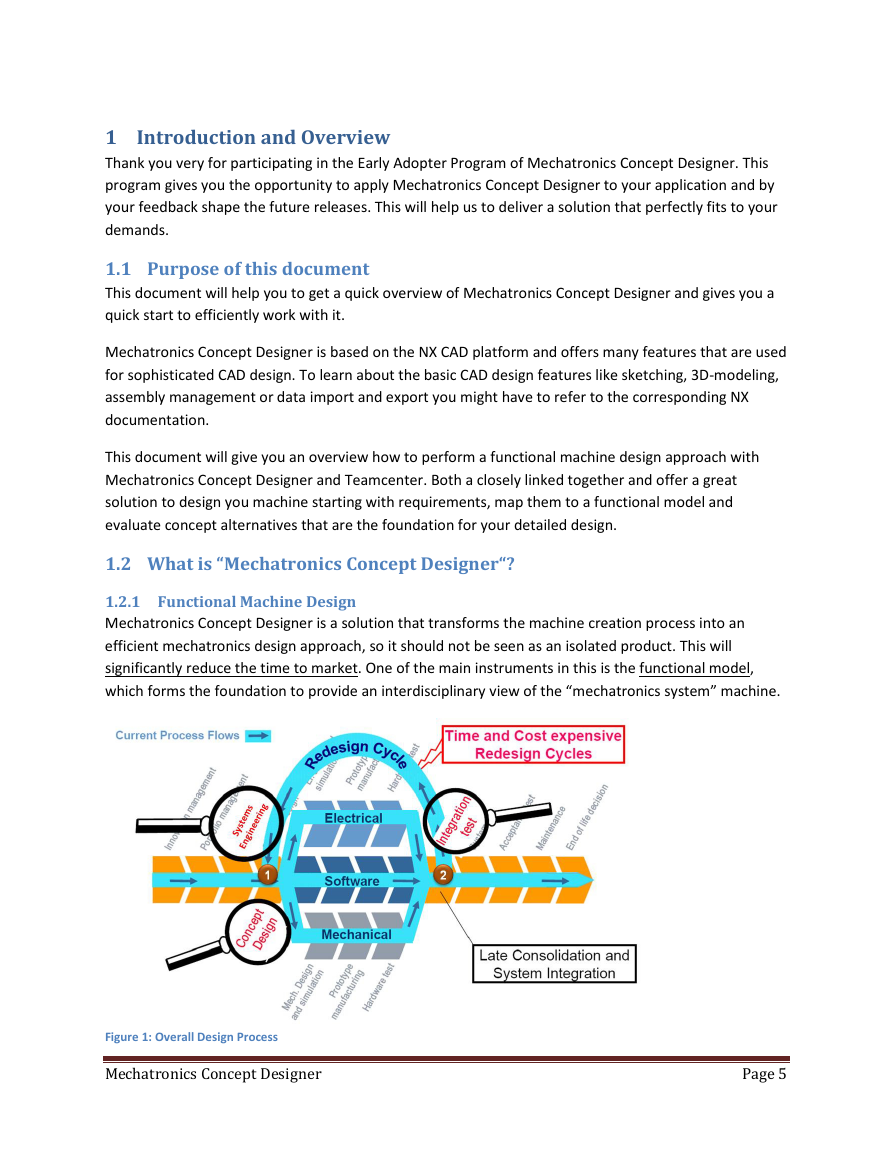
1 Introduction and Overview Thank you very for participating in the Early Adopter Program of Mechatronics Concept Designer. This program gives you the opportunity to apply Mechatronics Concept Designer to your application and by your feedback shape the future releases. This will help us to deliver a solution that perfectly fits to your demands. 1.1 Purpose of this document This document will help you to get a quick overview of Mechatronics Concept Designer and gives you a quick start to efficiently work with it. Mechatronics Concept Designer is based on the NX CAD platform and offers many features that are used for sophisticated CAD design. To learn about the basic CAD design features like sketching, 3D-modeling, assembly management or data import and export you might have to refer to the corresponding NX documentation. This document will give you an overview how to perform a functional machine design approach with Mechatronics Concept Designer and Teamcenter. Both a closely linked together and offer a great solution to design you machine starting with requirements, map them to a functional model and evaluate concept alternatives that are the foundation for your detailed design. 1.2 What is “Mechatronics Concept Designer“? 1.2.1 Functional Machine Design Mechatronics Concept Designer is a solution that transforms the machine creation process into an efficient mechatronics design approach, so it should not be seen as an isolated product. This will , significantly reduce the time to market. One of the main instruments in this is the functional model which forms the foundation to provide an interdisciplinary view of the “mechatronics system” machine. Figure 1: Overall Design Process Mechatronics Concept Designer Page 5
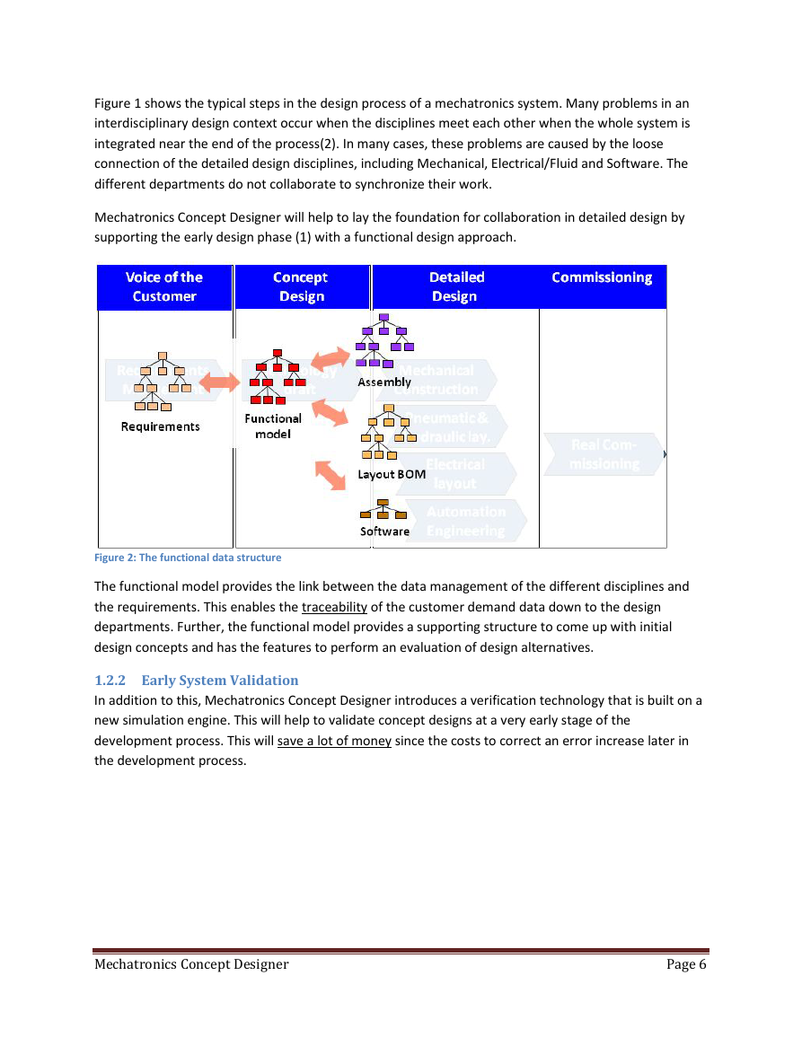
Figure 1 shows the typical steps in the design process of a mechatronics system. Many problems in an interdisciplinary design context occur when the disciplines meet each other when the whole system is integrated near the end of the process(2). In many cases, these problems are caused by the loose connection of the detailed design disciplines, including Mechanical, Electrical/Fluid and Software. The different departments do not collaborate to synchronize their work. Mechatronics Concept Designer will help to lay the foundation for collaboration in detailed design by supporting the early design phase (1) with a functional design approach. Figure 2: The functional data structure The functional model provides the link between the data management of the different disciplines and the requirements. This enables the traceability departments. Further, the functional model provides a supporting structure to come up with initial design concepts and has the features to perform an evaluation of design alternatives. of the customer demand data down to the design 1.2.2 Early System Validation In addition to this, Mechatronics Concept Designer introduces a verification technology that is built on a new simulation engine. This will help to validate concept designs at a very early stage of the development process. This will save a lot of money since the costs to correct an error increase later in the development process. Mechatronics Concept Designer Page 6
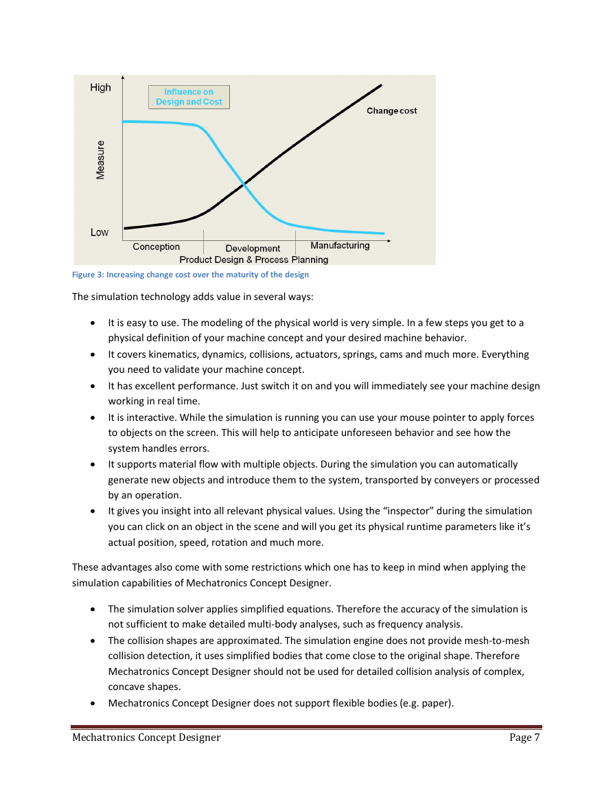
Figure 3: Increasing change cost over the maturity of the design The simulation technology adds value in several ways: • • • • • • It is easy to use. The modeling of the physical world is very simple. In a few steps you get to a physical definition of your machine concept and your desired machine behavior. It covers kinematics, dynamics, collisions, actuators, springs, cams and much more. Everything you need to validate your machine concept. It has excellent performance. Just switch it on and you will immediately see your machine design working in real time. It is interactive. While the simulation is running you can use your mouse pointer to apply forces to objects on the screen. This will help to anticipate unforeseen behavior and see how the system handles errors. It supports material flow with multiple objects. During the simulation you can automatically generate new objects and introduce them to the system, transported by conveyers or processed by an operation. It gives you insight into all relevant physical values. Using the “inspector” during the simulation you can click on an object in the scene and will you get its physical runtime parameters like it’s actual position, speed, rotation and much more. These advantages also come with some restrictions which one has to keep in mind when applying the simulation capabilities of Mechatronics Concept Designer. • The simulation solver applies simplified equations. Therefore the accuracy of the simulation is not sufficient to make detailed multi-body analyses, such as frequency analysis. • The collision shapes are approximated. The simulation engine does not provide mesh-to-mesh collision detection, it uses simplified bodies that come close to the original shape. Therefore Mechatronics Concept Designer should not be used for detailed collision analysis of complex, concave shapes. • Mechatronics Concept Designer does not support flexible bodies (e.g. paper). Mechatronics Concept Designer Page 7
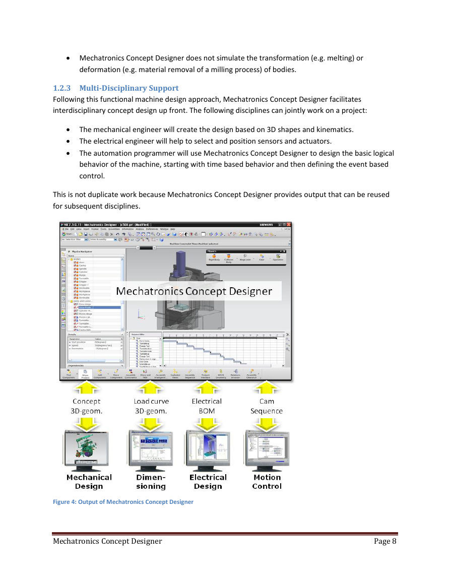
• Mechatronics Concept Designer does not simulate the transformation (e.g. melting) or deformation (e.g. material removal of a milling process) of bodies. 1.2.3 Multi-Disciplinary Support Following this functional machine design approach, Mechatronics Concept Designer facilitates interdisciplinary concept design up front. The following disciplines can jointly work on a project: • The mechanical engineer will create the design based on 3D shapes and kinematics. • The electrical engineer will help to select and position sensors and actuators. • The automation programmer will use Mechatronics Concept Designer to design the basic logical behavior of the machine, starting with time based behavior and then defining the event based control. This is not duplicate work because Mechatronics Concept Designer provides output that can be reused for subsequent disciplines. Figure 4: Output of Mechatronics Concept Designer Mechatronics Concept Designer Page 8
分享到:
收藏