Available online at www.sciencedirect.com
Journal of the Franklin Institute 352 (2015) 802–812
www.elsevier.com/locate/jfranklin
A novel scheme for demodulation of ACO-OFDM in the
presence of DC offset$
Tao Liu
School of Automation & Electrical Engineering, University of Science and Technology Beijing, Beijing 100083, China
Received 2 June 2014; received in revised form 19 September 2014; accepted 18 November 2014
Available online 6 December 2014
Abstract
Asymmetrically clipped optical orthogonal frequency division multiplexing (ACO-OFDM) has become
one of the most promising technologies for high speed optical wireless communications (OWCs). However,
as a key challenge, improving the demodulation performance of ACO-OFDM in practical systems has not
been well addressed. Most established demodulation schemes suffer from performance degradation either
due to discarding of even sub-carriers or interference of direct current (DC) offset, which is one of the most
common impairments in practical OWC systems. Up to our awareness, there was only one established
scheme (Dissanayake and Armstrong, 2011 [1]) that addressed ACO-OFDM demodulation in the presence
of DC offset, but it requires relatively high computation efforts. To deal with the challenge, we propose a
novel demodulation scheme for ACO-OFDM in this paper. By making use of the virtual clean window
(VCW), we develop methods to estimate and eliminate DC offset, so that the even sub-carriers of ACO-
OFDM can be explored to improve demodulation performance even in the presence of DC offset. Compared
with the scheme presented in (Dissanayake and Armstrong 2011 [1]), the proposed scheme significantly
reduces processing complexity. Simulation results are given to demonstrate the performance of the proposed
scheme.
& 2014 The Franklin Institute. Published by Elsevier Ltd. All rights reserved.
☆This work was supported by the National Natural Science Foundation of China under Grant 61372090, the Beijing
Higher Education Young Elite Teacher Project under Grant YETP0376, and the Fundamental Research Funds for the
Central Universities under Grant FRF-TP-14-116A2.
E-mail address: tgyxliu@gmail.com
http://dx.doi.org/10.1016/j.jfranklin.2014.11.014
0016-0032/& 2014 The Franklin Institute. Published by Elsevier Ltd. All rights reserved.
�
T. Liu / Journal of the Franklin Institute 352 (2015) 802–812
803
1. Introduction
Orthogonal frequency division multiplexing (OFDM) [2–5], which was originally developed
for radio communications, has recently been introduced as a solution for high speed data
transmission in optical wireless communications (OWCs) [6], such as visible light communica-
tions [7] and free space optical communications [8–10]. Compared with conventional single
carrier modulation, OFDM has many advantages [2] including efficient utilization of spectrum,
robustness to frequency selective channel fading and easy implementation by means of the fast
Fourier transform (FFT) and inverse FFT (IFFT), etc. However, OFDM in its original form is not
compatible with the intensity modulation and direct detection (IM/DD) [11] technologies that are
employed in most OWCs, because only real and positive signal can modulate the intensity of
light while original OFDM signal is bipolar and complex. To enable OFDM in IM/DD systems,
several optical OFDM solutions had been proposed, including direct current (DC) biased optical
OFDM (DCO-OFDM) [12], pulse-amplitude-modulated discrete multitone modulation (PAM-
DMT) [13], asymmetrically clipped optical OFDM (ACO-OFDM) [14], asymmetrically clipped
DC biased optical OFDM (ADO-OFDM) [15] and Flip-OFDM [16], etc.
In this paper, we are mainly concerned with ACO-OFDM, as it, on one hand, has higher
power efficiency than DCO-OFDM and PAM-DMT, and on the other hand is more widely
adopted than ADO-OFDM and Flip-OFDM. In ACO-OFDM, data are carried only by odd sub-
carriers while even sub-carriers are reserved empty. One benefit of such design is that, after
clipping negative amplitudes at zero, the clipping noise resides only on even sub-carriers and is
therefore orthogonal to the data on odd sub-carriers [14].
Demodulation performance, usually in terms of bit error rate (BER) or symbol error rate (SER)
achieved at certain transmitted power, is of special importance for ACO-OFDM [10,17,18], as
the average transmitted optical power is strictly limited in regulations [19] for eye safety. Several
schemes [14,20–26] have been established for demodulation of ACO-OFDM. However, as a key
challenge, improving the demodulation performance of ACO-OFDM in practical systems has not
been well addressed. In the odd sub-carrier scheme (OSCS) [14], the clipping noise on even sub-
carriers was simply discarded, while later researches [20–22] revealed that
the residual
information carried by the clipping noise can be further explored to improve demodulation
performance. Based on the fact that the clipping noise is equal to half of the absolute values of
un-clipped amplitude, a diversity combining scheme (DCS) was proposed in [20] and then
studied in [21,22] to combine the odd sub-carrier signal with the clipping noise in a non-linear
way. In [23,24], by making use of the anti-symmetry property of ACO-OFDM signal, a pairwise
maximum likelihood scheme (PMLS) was developed to cancel a significant amount of noise
before demodulation of ACO-OFDM. Compared with the OSCS, both the DCS and the PMLS
can achieve up to 3 dB performance gain [21,24]. It had been expected that joint utilization of the
DCS and the PMLS can lead to further improvement. However, it was shown in [25] by both
theoretical analysis and simulations that no additional benefit can be obtained by doing so. Most
recently, Dang et al. proposed an iterative minimum mean square error ACO-OFDM
demodulator [26], which in some cases can achieve about 10 dB performance improvement,
however its complexity is much higher than all the others.
Although some of the aforementioned schemes can improve the demodulation performance of
ACO-OFDM, they are vulnerable to non-ideal impairments, which are very likely to exist in
practical systems. DC offset is one of the most common impairments in practical ACO-OFDM
systems. Different from the intentional DC bias in DCO-OFDM, the DC offset in ACO-OFDM
comes from unwanted biasing of the transmitter LED, non-ideality of the receiver photodiode
�
804
T. Liu / Journal of the Franklin Institute 352 (2015) 802–812
circuit, or ambient light source [1,17]. Up to our awareness, ACO-OFDM demodulation in the
presence of DC offset was addressed only in [1], where two improved diversity combining
schemes (IDCSs) that are insensitive to DC offset were developed, but their complexity are
relative high, which may result in high hardware costs and/or power consumption in practice.
In this paper, we proposed a novel scheme for demodulation of ACO-OFDM in the presence
of DC offset. We first analyzed the basic idea of the PMLS, based on which we proposed and
illustrated the concept of virtual clean window (VCW) in ACO-OFDM. We then derived the
decision criterion for identification of the VCW in the presence of DC offset. By making use of
the identified VCW, we developed corresponding methods for DC offset estimation and
elimination, so that
the even sub-carriers of ACO-OFDM can be explored to improve
demodulation performance even when there is DC offset. Compared with the scheme established
in [1], the proposed scheme significantly reduces processing complexity in that the number of
required FFT/IFFT blocks is reduced by 1.
The rest of this paper is organized as follows. Mathematical model of ACO-OFDM is
introduced in Section 2. In Section 3, the proposed scheme is developed in detail. Simulation
results and corresponding analysis are given in Section 4 to demonstrate the performance of the
proposed scheme in comparison with the established ones. Finally, conclusions are drawn in the
last section.
2. ACO-OFDM system model
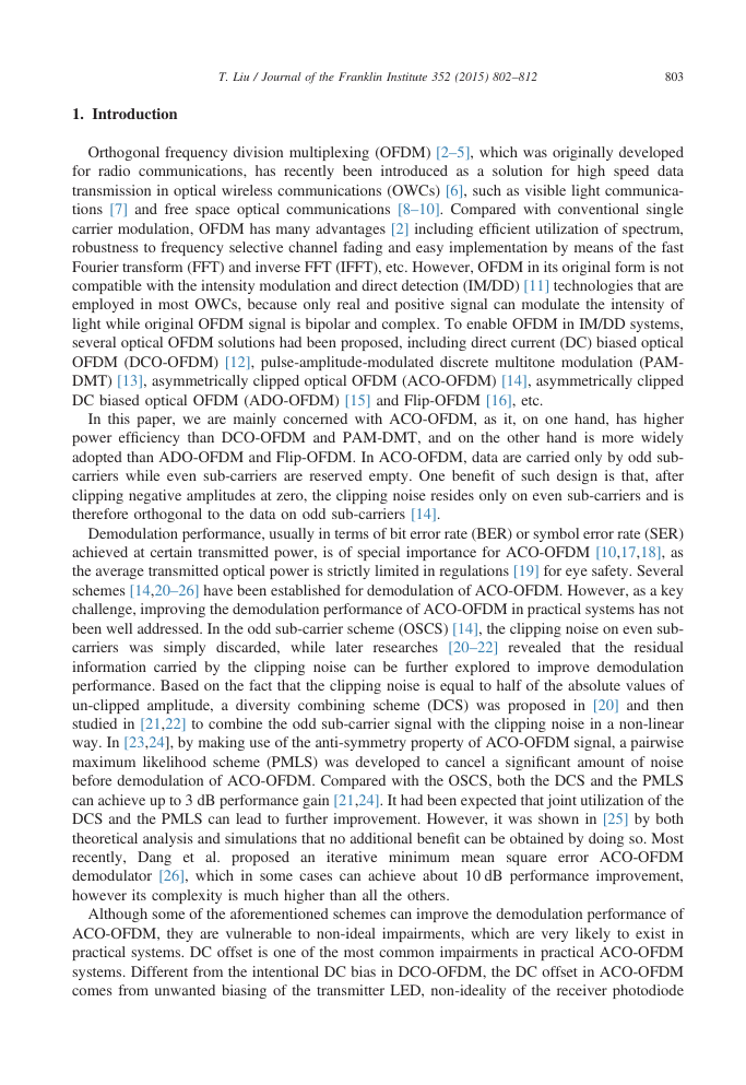
Consider an ACO-OFDM system with totally N sub-carriers as shown in Fig. 1. In the transmitter,
a set of N=4 data symbols S0 9½S0; …; SN=4� 1T drawn from a certain constellation, e.g. PSK or
QAM, are Hermitian symmetrically extended to S1 9½S0; …; SN=4� 1; Sn
0T, and then
N=4� 1
interleaved with N=2 zeros as S2 9½0; S0; …; 0; SN=4� 1; 0; Sn
0T, before mapped onto
; …; 0; Sn
the N sub-carriers. And then, S2 is converted by a N-point IFFT to generate a block of time domain
OFDM signal s2 9½s2ð0Þ; …; s2ðN�1ÞT, where
; …; Sn
N=4� 1
ð1Þ
s2ðnÞ ¼ ∑N � 1
S2ðkÞejð2π=NÞkn;
k ¼ 0
�
�
s2 nð Þ ¼ �s2 n þ N
2
for n ¼ 0; …; N�1, with S2ðkÞ being the kth element of S2. The design of S2 ensures that data are
carried only by odd sub-carriers and the time domain signal s2 is real and anti-symmetrical [24], i.e.
ð2Þ
;
Fig. 1. ACO-OFDM system.
�
if s2ðnÞZ0
if s2ðnÞo0
��
0
�
T. Liu / Journal of the Franklin Institute 352 (2015) 802–812
805
for n ¼ 0; …; N=2�1. After the IFFT, cyclic prefix (CP) is inserted in front of each OFDM block to
avoid inter-symbol interference (ISI). As optical IM accepts only positive signal,
the negative
amplitudes of s2 is clipped at zero to create the clipped digital signal s3 9½s3ð0Þ; …; s3ðN�1ÞT where
ð3Þ
s3ðnÞ ¼ s2ðnÞ
(
;
or equivalently [21]
s3 nð Þ ¼ 1
2
s2 nð Þ þ s2 nð Þj;
ð4Þ
for n ¼ 0; …; N�1. s3 is then converted to analog signal s3ðtÞ by the digital to analog converter
(DAC) and finally transmitted into diffuse optical channel by an electrical to optical converter such as
LED. In the receiver, a photodetector converts the received optical signal to electrical signal r0ðtÞ,
which can be expressed as
r0ðtÞ ¼ hðtÞns3ðtÞ þ d0 þ w0ðtÞ;
ð5Þ
where n denotes convolution. d0 represents the DC offset that exists in most practical ACO-OFDM
system, and w0ðtÞ is the additive white Gaussian noise (AWGN). After analog to digital conversion and
CP removal, the signal is transformed into frequency domain by FFT and then fed into an equalizer
where channel fading is compensated. Let R1 9½R1ð0Þ; …; R1ðkÞT denote the output of the equalizer.
Since the clipping noise resides only on the even sub-carriers, ignoring noise and assuming perfect
knowledge of channel fading, we have [14]
R1 kð Þ ¼ 1
2S2 kð Þ;
for k ¼ 1; 3; 5; …; N�1.
ð6Þ
3. Proposed scheme for demodulation of ACO-OFDM in the presence of DC offset
The most simple scheme for demodulation of ACO-OFDM signal is the OSCS, which restores
the data symbols directly from the odd sub-carriers according to Eq. (6) as
^Sk ¼ S2ð2k þ 1Þ ¼ 2R1ð2k þ 1Þ;
ð7Þ
for k ¼ 0; 1; 2; …; N=4�1. The OSCS is very easy to be implemented, but its performance is not
satisfactory, as it simply discards the data dependent clipping noise on the even sub-carriers. By
further exploring the clipping noise,
the DCS and the PMLS successfully improve the
demodulation performance, however both of them are vulnerable to DC offset that commonly
exists in practical OWCs. Following the basic ideas of the PMLS, we propose a novel scheme in
this paper to address the challenge of improving the demodulation performance of ACO-OFDM
in the presence of DC offset.
First, we introduce the concept of VCW, which is the basis of our proposed scheme. Due to
the clipping in the transmitter, ideal ACO-OFDM signal consists of many zeros. At the receiver
end, these zeros form a virtual window, which is very ‘clean’ for observation of impairments and
noise that there is no interference from data signal. Thus, it is referred to as a virtual clean
window in this paper. In light of the VCW, we can find that all the non-zero amplitudes in the
VCW are reset to zeros in the PMLS. If there is no DC offset, the demodulation performance can
thus be apparently improved as a large amount of noise has been canceled. However, in the
presence of DC offset, the demodulation performance will be degraded by the DC offset out of
�
806
T. Liu / Journal of the Franklin Institute 352 (2015) 802–812
the VCW as it cannot be canceled by the resetting. To address this issue, we, in our scheme,
further explore the VCW to deal with both DC offset and noise simultaneously. First, we transfer
the equalizer output R1 back to time domain by means of IFFT
r1ðnÞ ¼ ∑N � 1
k ¼ 0
R1ðkÞejð2π=NÞkn ¼ s3ðnÞ þ d1 þ w1ðnÞ
ð8Þ
for n ¼ 0; …; N�1, where d1 and w1ðnÞ represent the DC offset and noise after equalization,
respectively. Second, we must identify the position of the VCW in the presence of DC offset.
According to the anti-symmetry property (2) and clipping operation (3), the identification can be
simplified to a series of pairwise detection between two hypotheses [24], H0 : s3ðnÞ40; s3ðn þ
N=2Þ ¼ 0 or H1 : s3ðnÞ ¼ 0; s3ðn þ N=2Þ40, for n ¼ 0; …; N=2�1. Based on the established
works in [24], if there is no DC offset, i.e. d1 ¼ 0, the decision criterion can be expressed as
ð9Þ
for n ¼ 0; …; N=2�1. And then, if there is DC offset, the decision criterion for d1 a0 can be
derived based on Eq. (9) in a straightforward way as
r1 nð Þ ≷H0
H1
H1
�d1;
r1 nð Þ�d1 ≷H0
ð10Þ
for n ¼ 0; …; N=2�1. Obviously, the identical terms d1 on both sides of Eq. (10) can be
canceled and therefore Eq. (10) becomes back to Eq. (9). In other words, the decision criterion
for identification of the VCW in the presence of DC offset is the same as that for cases without
DC offset. Thus, based on Eq.
index
I 9fni; i ¼ 0; …; N=2�1g where
if H0 is true
if H1 is true
the VCW can be expressed as a set of
ni ¼ i þ N
ð11Þ
(
(9),
i
2
;
;
�
�
r1 n þ N
2
�
r1 n þ N
2
�
Given the identified VCW, we can then make an estimation of the DC offset by
^d 1 ¼ 2
N
ðN=2Þ� 1
∑
i ¼ 0
r1 nið
Þ ¼ d1 þ e nð Þ
ð12Þ
where e(n) is the estimation error whose power is as large as 4=N2 of that of w1ðnÞ. With
sufficiently large N, which is usually satisfied in practical OWCs, the estimation error e(n)
becomes so small that we can approximately take ^d 1 as the true DC offset. Now, we can cancel
the DC offset and noise in r1ðnÞ by
r2ðnÞ ¼ r1ðnÞ� ^d 1
0
nAI
nAI
ð13Þ
(
n ¼ 0; …; N�1, which
I \ I ¼ ∅ and
for
I [ I ¼ f0; 1; …; N�1g. Within the VCW, all the amplitudes are set to zeros so that both DC
offset and noise are completely eliminated. Out of the VCW, we have
complementary
i.e.
the
set
of
is
I,
r2ðnÞ ¼ s1ðnÞ þ w2ðnÞ
ð14Þ
�
T. Liu / Journal of the Franklin Institute 352 (2015) 802–812
807
where w2ðnÞ9w1ðnÞ�eðnÞ, i.e. DC offset is removed while noise is left. To further reduce the
influence of noise, the DC free signal r2ðnÞ is then clipped at zero as
(
r3ðnÞ ¼ r2ðnÞ
0
r2ðnÞZ0
r2ðnÞo0
ð15Þ
for n ¼ 0; …; N�1, to remove the negative noise [24]. Finally, we can simply restore the data
directly from the odd sub-carriers of r3ðnÞ as
^Sk ¼ 2 ∑N � 1
n ¼ 0
r3ðnÞe� jð2π=NÞð2kþ1Þn;
for k ¼ 0; 1; 2; …; N=4�1.
ð16Þ
Based on the introduction given above, it can be concluded that the proposed demodulation
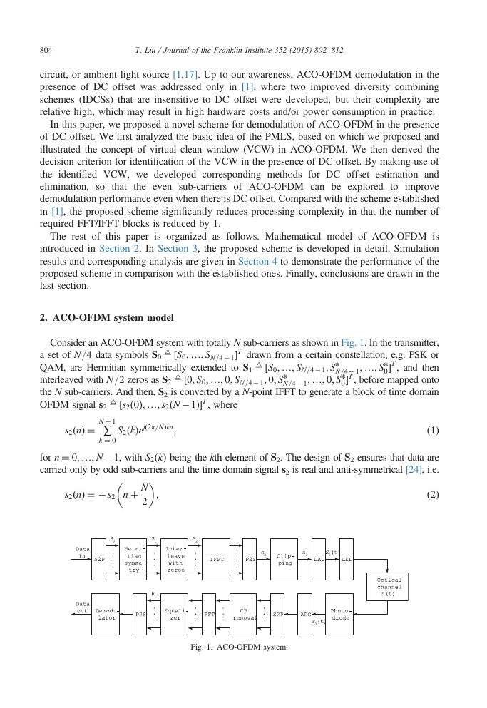
scheme restore the original data from the equalizer output through the following steps:
� Convert
� Identify the VCW, i.e. the index set I, according to the criterion
the equalizer output R1ðkÞ
k ¼ 0R1ðkÞejð2π=NÞkn for n ¼ 0; …; N�1.
to time domain sequence r1ðnÞ by IFFT as
r1ðnÞ ¼ ∑N � 1
�
�
r1 n þ N
2
r1 nð Þ
≷nþðN=2Þ A I
n A I
for n ¼ 0; …; N=2�1.
� Obtain estimation of the DC offset d1 by ^d 1 ¼ ð2=NÞ∑n A Ir1ðnÞ.
� Eliminate DC offset and noise from r1ðnÞ by r2ðnÞ ¼ r1ðnÞ� ^d 1 for nAI , and r2ðnÞ ¼ 0 for
nAI.
� Reduce the influence of negative noise from r2ðnÞ by clipping as r3ðnÞ ¼ r2ðnÞ for r2ðnÞZ0,
and r3ðnÞ ¼ 0 for r2ðnÞo0.
� Restore data symbols S(k) from r3ðnÞ by FFT as ^Sk ¼ 2∑N � 1
n ¼ 0r3ðnÞe� jð2π=NÞð2kþ1Þn for
k ¼ 0; 1; 2; …; N=4�1.
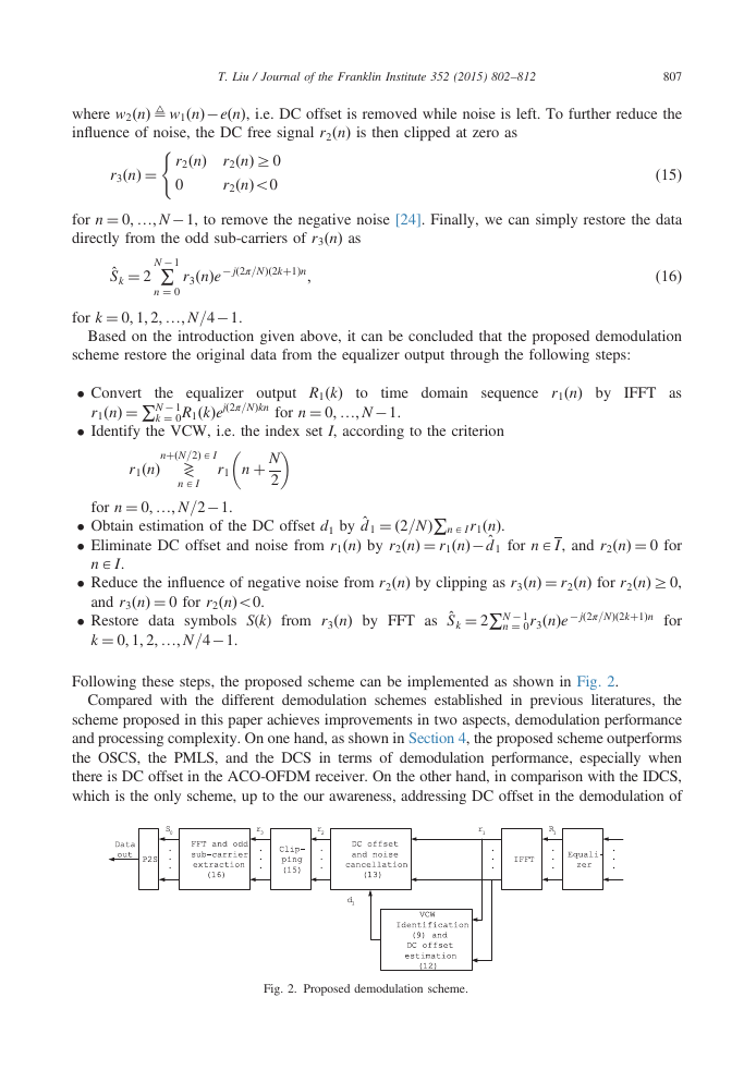
Following these steps, the proposed scheme can be implemented as shown in Fig. 2.
Compared with the different demodulation schemes established in previous literatures, the
scheme proposed in this paper achieves improvements in two aspects, demodulation performance
and processing complexity. On one hand, as shown in Section 4, the proposed scheme outperforms
the OSCS, the PMLS, and the DCS in terms of demodulation performance, especially when
there is DC offset in the ACO-OFDM receiver. On the other hand, in comparison with the IDCS,
which is the only scheme, up to the our awareness, addressing DC offset in the demodulation of
Fig. 2. Proposed demodulation scheme.
�
808
T. Liu / Journal of the Franklin Institute 352 (2015) 802–812
ACO-OFDM, the proposed scheme significantly reduces processing complexity. In Tables 1 and 2,
we summarize the major processing of the IDCS [1] and the proposed scheme, respectively. Note
that the abbreviations CM and CA stands for the number of complex multiplications and complex
additions, respectively. Based on the tables, it is apparent that the improvement in processing
complexity is mainly achieved by reducing the number of required FFT and IFFT, which are the
most computation intensive processing in demodulation.
4. Simulation results and analysis
In this section, performance of the proposed demodulation scheme is demonstrated by
simulations, where an ACO-OFDM system with 64 sub-carriers carrying 16-QAM modulated
symbols is emulated to work over optical wireless channel. At receiver end, several different
demodulation schemes are evaluated for comparison. Besides the proposed scheme, they include
the OSCS, the PMLS, the DCS and its improved version IDCS with weighting factor [20–22]
α¼0.5. As optical OFDM has strong tolerance to attenuation and dispersion, we assume in the
simulations that channel losses and dispersion are fully compensated by the equalizer. SER is
taken as the key metric for performance comparison among different schemes.
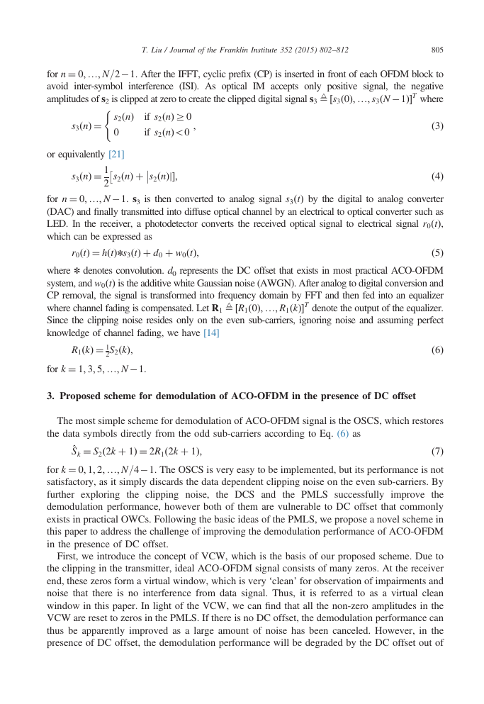
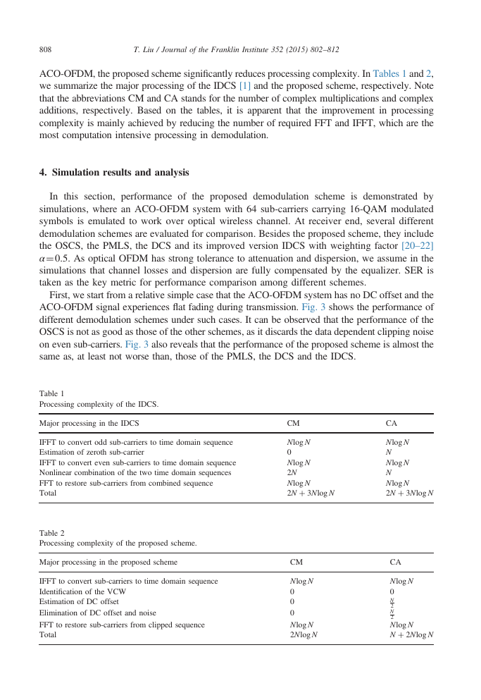
First, we start from a relative simple case that the ACO-OFDM system has no DC offset and the
ACO-OFDM signal experiences flat fading during transmission. Fig. 3 shows the performance of
different demodulation schemes under such cases. It can be observed that the performance of the
OSCS is not as good as those of the other schemes, as it discards the data dependent clipping noise
on even sub-carriers. Fig. 3 also reveals that the performance of the proposed scheme is almost the
same as, at least not worse than, those of the PMLS, the DCS and the IDCS.
Table 1
Processing complexity of the IDCS.
Major processing in the IDCS
CM
CA
IFFT to convert odd sub-carriers to time domain sequence
Estimation of zeroth sub-carrier
IFFT to convert even sub-carriers to time domain sequence
Nonlinear combination of the two time domain sequences
FFT to restore sub-carriers from combined sequence
Total
Nlog N
0
Nlog N
2N
Nlog N
2N þ 3Nlog N
Nlog N
N
Nlog N
N
Nlog N
2N þ 3Nlog N
Table 2
Processing complexity of the proposed scheme.
Major processing in the proposed scheme
IFFT to convert sub-carriers to time domain sequence
Identification of the VCW
Estimation of DC offset
Elimination of DC offset and noise
FFT to restore sub-carriers from clipped sequence
Total
CM
Nlog N
0
0
0
Nlog N
2Nlog N
CA
Nlog N
0
N
2
N
2
Nlog N
N þ 2Nlog N
�
T. Liu / Journal of the Franklin Institute 352 (2015) 802–812
809
R
E
S
R
E
S
100
10−1
10−2
10−3
10−4
10−5
0
Demodulation Performance
OSCS
PMLS
DCS
IDCS
Proposed
5
10
SNR (dB)
15
20
Fig. 3. SER performance in flat fading channel without DC offset.
100
10−1
10−2
10−3
10−4
10−5
0
Demodulation Performance
OSCS
PMLS
DCS
IDCS
Proposed
5
10
SNR (dB)
15
20
25
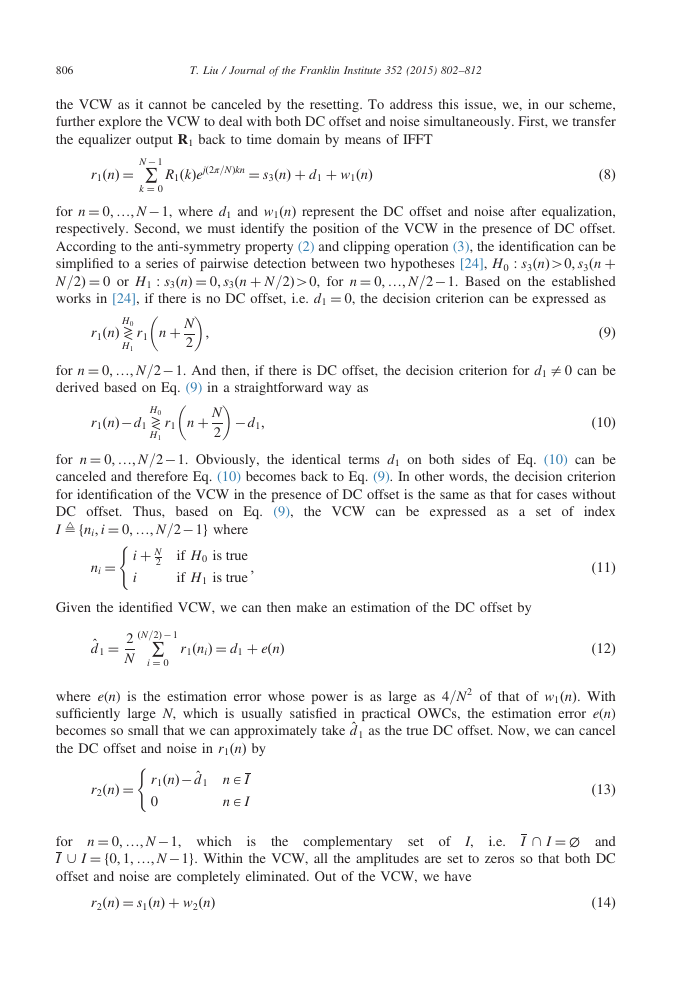
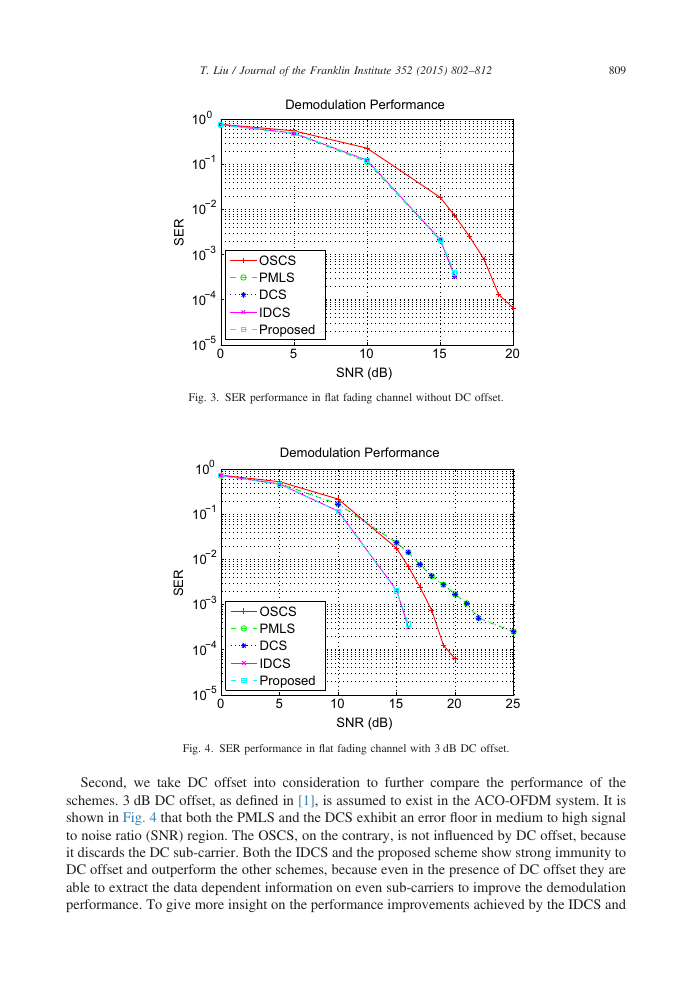
Fig. 4. SER performance in flat fading channel with 3 dB DC offset.
Second, we take DC offset into consideration to further compare the performance of the
schemes. 3 dB DC offset, as defined in [1], is assumed to exist in the ACO-OFDM system. It is
shown in Fig. 4 that both the PMLS and the DCS exhibit an error floor in medium to high signal
to noise ratio (SNR) region. The OSCS, on the contrary, is not influenced by DC offset, because
it discards the DC sub-carrier. Both the IDCS and the proposed scheme show strong immunity to
DC offset and outperform the other schemes, because even in the presence of DC offset they are
able to extract the data dependent information on even sub-carriers to improve the demodulation
performance. To give more insight on the performance improvements achieved by the IDCS and
�



 2023年江西萍乡中考道德与法治真题及答案.doc
 2012年重庆南川中考生物真题及答案.doc
 2013年江西师范大学地理学综合及文艺理论基础考研真题.doc
 2020年四川甘孜小升初语文真题及答案I卷.doc
 2020年注册岩土工程师专业基础考试真题及答案.doc
 2023-2024学年福建省厦门市九年级上学期数学月考试题及答案.doc
 2021-2022学年辽宁省沈阳市大东区九年级上学期语文期末试题及答案.doc
 2022-2023学年北京东城区初三第一学期物理期末试卷及答案.doc
 2018上半年江西教师资格初中地理学科知识与教学能力真题及答案.doc
 2012年河北国家公务员申论考试真题及答案-省级.doc
 2020-2021学年江苏省扬州市江都区邵樊片九年级上学期数学第一次质量检测试题及答案.doc
 2022下半年黑龙江教师资格证中学综合素质真题及答案.doc