CANDIDE-3
– AN UPDATED PARAMETERISED FACE
Jörgen Ahlberg
Image Coding Group
Dept. of Electrical Engineering, Linköping University
SE-581 83 Linköping, SWEDEN
http://www.icg.isy.liu.se
ahlberg@isy.liu.se
Report No. LiTH-ISY-R-2326, January 2001
Abstract
During the last decade, CANDIDE has been a popular face model in many research labs
around the world. One reason has been that it is a very simple model, another that it is
publically available. There are, however, drawbacks with the model, mostly due to its
simplicity. Also, the emergence of the MPEG-4 standard for face animation has actual-
ized the need of an update, making the model compatible with the facial animation and
definition parameters (FAPs and FDPs) defined in MPEG-4.
This report documents an updated version of CANDIDE, fulfilling the demands set by
MPEG-4 and being somewhat less crude. The relation between the CANDIDE entities
(vertices, Action Units) and the MPEG-4 parameters are available in tables in the appen-
dices.
1. Introduction
CANDIDE is a parameterised face mask specifi-
cally developed for model-based coding of
human faces. Its low number of polygons
(approximately 100) allows fast reconstruction
with small computing power.
CANDIDE is controlled by global and local
Action Units (AUs). The global ones correspond
to rotations around three axes. The local Action
Units control the mimics of the face so that dif-
ferent expressions can be obtained.
The concept of Action Units was first
described more than 30 years ago by the Swed-
ish researcher Carl-Herman Hjortsjö [6]. This
work was later extended (by Paul Ekman and
Wallace V. Friesen at the University of Califor-
nia Medical Center) to what is called FACS, the
Facial Action Coding System [2].
The CANDIDE model was created by Mikael
Rydfalk at Linköping University in 1987 [10].
This work was motivated by the first attempts to
perform image compression through animation
[3][4], later called model-based, object-based or
semantic coding.
-3
The CANDIDE model became known to a
larger public through journal articles [5][7][8].
It is publically available and is now used by
research groups around the world.
1.1. The earlier CANDIDE versions
The original CANDIDE, described in the report
by Rydfalk [10], contained 75 vertices and 100
triangles. This version is rarely used.
The most widespread version, the de facto
standard CANDIDE model, is a slighlty modified
model with 79 vertices, 108 surfaces and 11
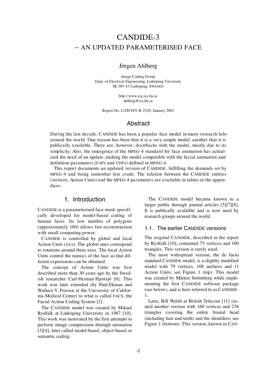
Action Units; see Figure 1 (top). This model
was created by Mårten Strömberg while imple-
menting the first CANDIDE software package
(see below), and is here referred to as CANDIDE-
1.
Later, Bill Welsh at British Telecom [11] cre-
ated another version with 160 vertices and 238
triangles covering
the entire frontal head
(including hair and teeth) and the shoulders; see
Figure 1 (bottom). This version, known as CAN-
�
-2
Jörgen Ahlberg
Figure 1. Top: CANDIDE-1 with 79 vertices and 108 surfaces.
Bottom: CANDIDE-2 with 160 vertices and 238 surfaces.
DIDE-2 is also included in the CANDIDE soft-
ware package, but is delivered with only six
Action Units.
1.2. About this Report
This report partly replaces the original report
by Rydfalk [10]. However, no detailed descrip-
tions of the Action Units are found here
(instead, see [2][6][10]). A future update may
contain such descriptions.
Section 2 describes the changes in CANDIDE-3
(compared to CANDIDE-1), and Section 3 treats
the parameterisation and control of wireframe
face models. Section 4 describes the Action
Units and Action Unit Vectors, and Section 5 the
Shape Units (a new feature in CANDIDE-3). Sec-
tion 6, finally, describes the relation between
CANDIDE-3 and MPEG-4. The appendices con-
tain tables defining Action Units, Action Unit
Vectors, MPEG-4 facial feature points and CAN-
DIDE vertices, and the file format for wfm-files.
�
CANDIDE-3 – an updated parameterised face
-1
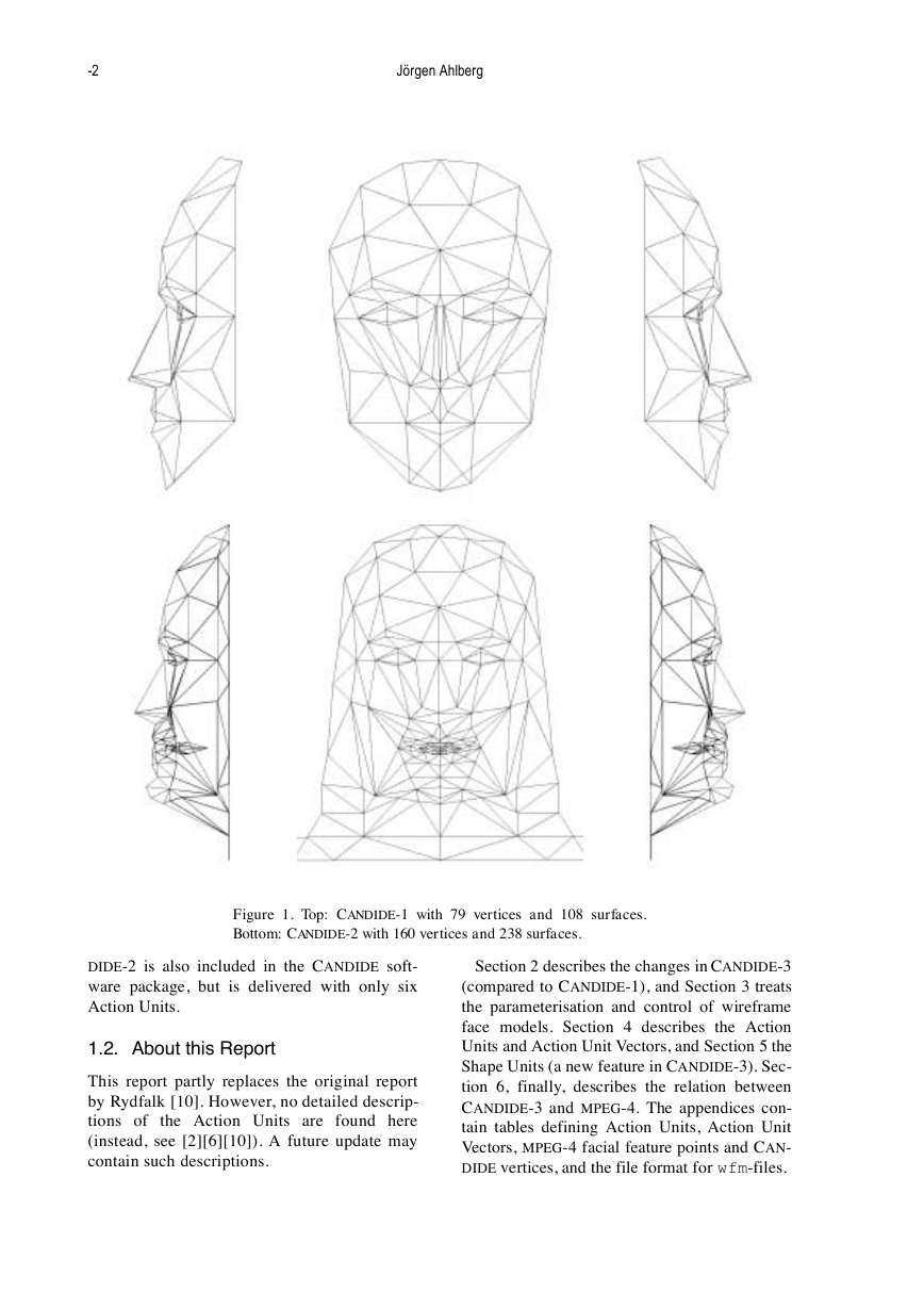
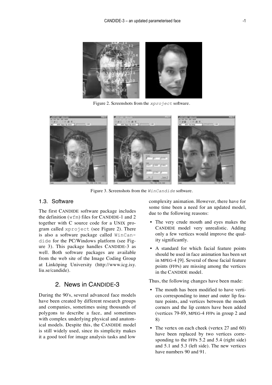
Figure 2. Screenshots from the xproject software.
Figure 3. Screenshots from the WinCandide software.
1.3. Software
The first CANDIDE software package includes
the definition (wfm) files for CANDIDE-1 and 2
together with C source code for a UNIX pro-
gram called xproject (see Figure 2). There
is also a software package called WinCan-
dide for the PC/Windows platform (see Fig-
ure 3). This package handles CANDIDE-3 as
well. Both software packages are available
from the web site of the Image Coding Group
at Linköping University (http://www.icg.isy.
liu.se/candide).
2. News in CANDIDE-3
During the 90's, several advanced face models
have been created by different research groups
and companies, sometimes using thousands of
polygons to describe a face, and sometimes
with complex underlying physical and anatom-
ical models. Despite this, the CANDIDE model
is still widely used, since its simplicity makes
it a good tool for image analysis tasks and low
complexity animation. However, there have for
some time been a need for an updated model,
due to the following reasons:
The very crude mouth and eyes makes the
CANDIDE model very unrealistic. Adding
only a few vertices would improve the qual-
ity significantly.
A standard for which facial feature points
should be used in face animation has been set
in MPEG-4 [9]. Several of those facial feature
points (FFPs) are missing among the vertices
in the CANDIDE model.
Thus, the following changes have been made:
The mouth has been modified to have verti-
ces corresponding to inner and outer lip fea-
ture points, and vertices between the mouth
corners and the lip centers have been added
(vertices 79-89, MPEG-4 FFPs in group 2 and
8)
The vertex on each cheek (vertex 27 and 60)
have been replaced by two vertices corre-
sponding to the FFPs 5.2 and 5.4 (right side)
and 5.1 and 5.3 (left side). The new vertices
have numbers 90 and 91.
�
0
Jörgen Ahlberg
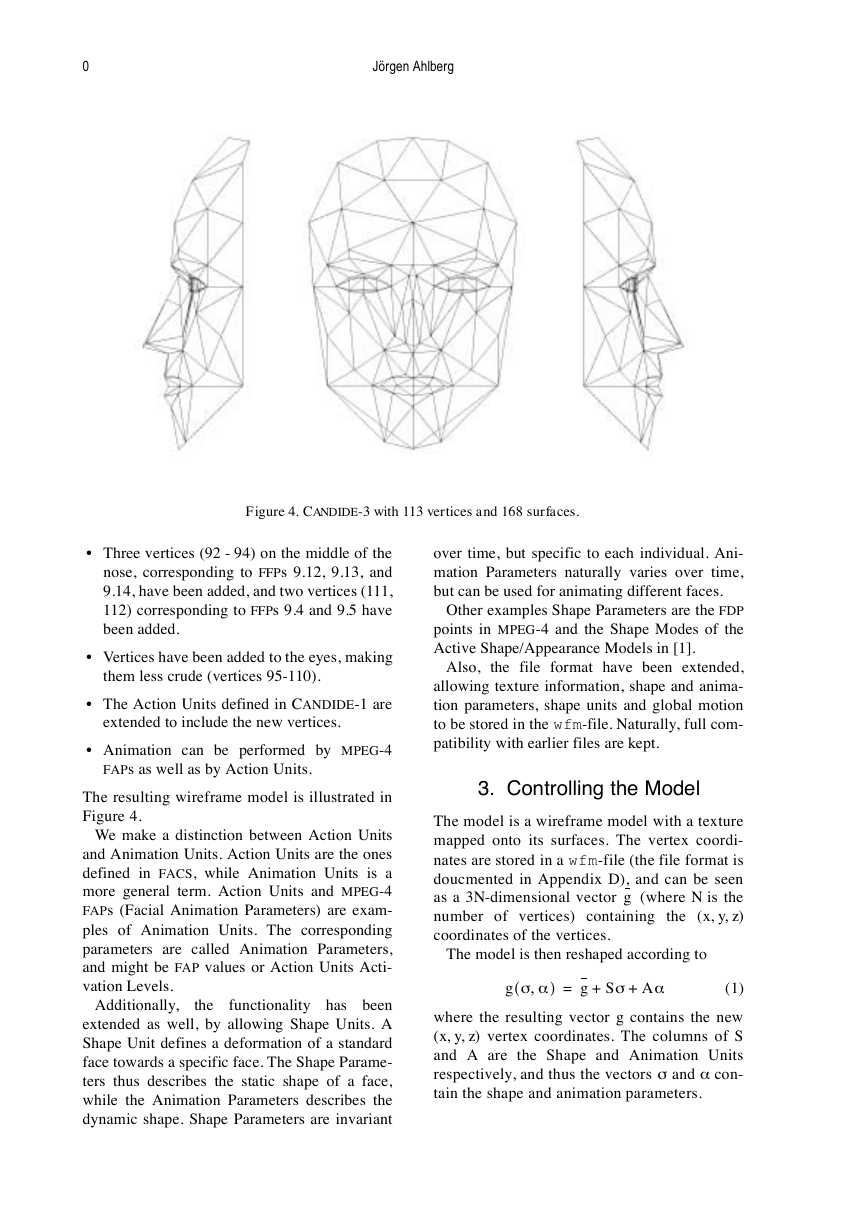
Figure 4. CANDIDE-3 with 113 vertices and 168 surfaces.
Three vertices (92 - 94) on the middle of the
nose, corresponding to FFPs 9.12, 9.13, and
9.14, have been added, and two vertices (111,
112) corresponding to FFPs 9.4 and 9.5 have
been added.
Vertices have been added to the eyes, making
them less crude (vertices 95-110).
The Action Units defined in C ANDIDE-1 are
extended to include the new vertices.
Animation can be performed by MPEG-4
FAPs as well as by Action Units.
The resulting wireframe model is illustrated in
Figure 4.
We make a distinction between Action Units
and Animation Units. Action Units are the ones
defined in FACS, while Animation Units is a
more general term. Action Units and MPEG-4
FAPs (Facial Animation Parameters) are exam-
ples of Animation Units. The corresponding
parameters are called Animation Parameters,
and might be FAP values or Action Units Acti-
vation Levels.
the
Additionally,
functionality has been
extended as well, by allowing Shape Units. A
Shape Unit defines a deformation of a standard
face towards a specific face. The Shape Parame-
ters thus describes the static shape of a face,
while the Animation Parameters describes the
dynamic shape. Shape Parameters are invariant
over time, but specific to each individual. Ani-
mation Parameters naturally varies over time,
but can be used for animating different faces.
Other examples Shape Parameters are the FDP
points in MPEG-4 and the Shape Modes of the
Active Shape/Appearance Models in [1].
Also, the file format have been extended,
allowing texture information, shape and anima-
tion parameters, shape units and global motion
to be stored in the wfm-file. Naturally, full com-
patibility with earlier files are kept.
3. Controlling the Model
The model is a wireframe model with a texture
mapped onto its surfaces. The vertex coordi-
nates are stored in a wfm-file (the file format is
doucmented in Appendix D), and can be seen
as a 3N-dimensional vector
(where N is the
number of vertices) containing the (x, y, z)
coordinates of the vertices.
g
The model is then reshaped according to
g σ α,
(
)
=
g Sσ Aα
+
+
(1)
where the resulting vector g contains the new
(x, y, z) vertex coordinates. The columns of S
and A are the Shape and Animation Units
respectively, and thus the vectors σ and α con-
tain the shape and animation parameters.
�
CANDIDE-3 – an updated parameterised face
1
Since we also want to perform global motion,
we need a few more parameters for rotation,
scaling, and translation. Thus, we replace (1)
with
g
+
(
Rs g Sσ Aα
+
=
)
(
,
R rx r,
y rz
(
t tx t,
t
=
,
y tz
R
=
where
is the scale, and
vector.
)
t+
(2)
is a rotation matrix, s
the translation
)
The geometry of our model is thus parameter-
ized by the parameter vector
p
=
[
=
ν σ α
]
[
,
,
rx r,
,
,
y rz s tx t,
,
(3)
,
,
y tz
σ α
,
]
where ν is the vector of global motion parame-
ters. The file format supports having different
scalings in the three dimensiones, i.e,
g
=
RS3 g Sσ Aα
+
+
(
)
t+
,
(4)
where S3 = S3(sx , sy , sz).
The Animation Units can be implementations
of the MPEG-4 FAPs or Action Unit Vectors
implementing the Action Units from FACS.
4. The Action Units and Action
Units Vectors
In earlier CANDIDE versions there is a slight
confusion about Action Units (AUs) and Action
Unit Vectors (AUVs). In the original report
[10], the distinction is quite clear; an Action
Unit is something that you do in your face with
a (single) facial muscle activation, and an
Action Unit Vector is the corresponding imple-
mentation (of one or more Action Units) in the
CANDIDE model. For example, the Action
Units 42 (Slit), 43 (Eyes Closed), 44 (Squint),
and 45 (Blink) are all implemented by Action
Unit Vector 6 – it is quite obvious that a quick
blink with the eyes is a different action than
closing the eyes, but it is also obvious that they
should be implemented by the same Action
Unit Vector.
So, what is then the confusion about? In the
first CANDIDE software package (including the
wfm-files
the
xproject program), the AUVs are called
Action Units, but use the numbering of the
AUVs. Thus, in some cases this numbering has
for CANDIDE-1 and 2, and
been used as the AU numbering. Further, the
AUV numbering in CANDIDE-1 is not identical
to the numbering in [10], and CANDIDE-2 con-
tains yet a slightly different numbering.
In CANDIDE-3, the numbering from [10] is
used. Listings of the Action Units and Action
Units Vectors can be found in Appendix C.
The Action Unit Vectors are then generalized
to Animation Units, since they also represent
(for example) FAPs. Animation Units implem-
nting most of the MPEG-4 FAPs (see Section 6)
are included in the definition file of CANDIDE-
3.
5. The Shape Units
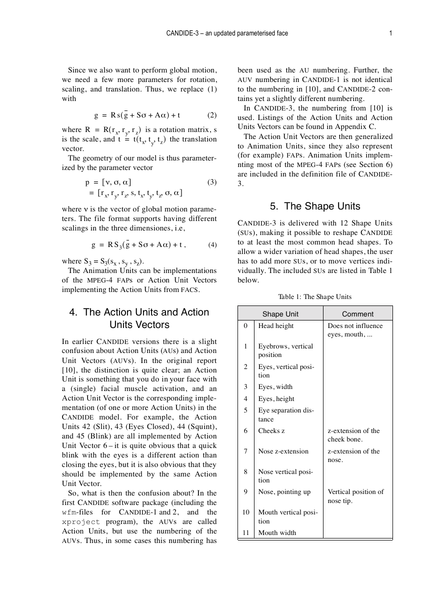
CANDIDE-3 is delivered with 12 Shape Units
(SUs), making it possible to reshape CANDIDE
to at least the most common head shapes. To
allow a wider variation of head shapes, the user
has to add more SUs, or to move vertices indi-
vidually. The included SUs are listed in Table 1
below.
Table 1: The Shape Units
Comment
Does not influence
eyes, mouth, ...
z-extension of the
cheek bone.
z-extension of the
nose.
Vertical position of
nose tip.
Shape Unit
Head height
Eyebrows, vertical
position
Eyes, vertical posi-
tion
Eyes, width
Eyes, height
Eye separation dis-
tance
Cheeks z
Nose z-extension
Nose vertical posi-
tion
Nose, pointing up
0
1
2
3
4
5
6
7
8
9
10 Mouth vertical posi-
tion
11 Mouth width
�
2
Jörgen Ahlberg
6. Relation to MPEG-4 Face
Animation
To make a face model compatible with MPEG-4
Face Animation, two things need to be deter-
mined: What FFPs correspond to which verti-
ces, and the FAP units (FAPUs).
6.1. Vertices and FFPs
Most FFPs have their direct correspondance
even in CANDIDE-1, and with the addition of
vertex 89-112 almost all FFPs are represented.
There are a few exceptions though:
C ANDIDE has no tongue, thus the FFPs in
group 6 have no corresponding vertices.
The entire head is not represented by C AN-
DIDE, and thus the top of the spine (FFP 7.1)
and the back of the skull (FFP 11.6) does not
correspond to any vertices.
C ANDIDE-3 has (in contrast to CANDIDE-2)
no teeth (FFPs 9.9 - 9.11).
C ANDIDE has no ears (FFPs 10.1 - 10.6).
C ANDIDE-3 has no hair, and thus no hair
thickness (FFP 11.5).
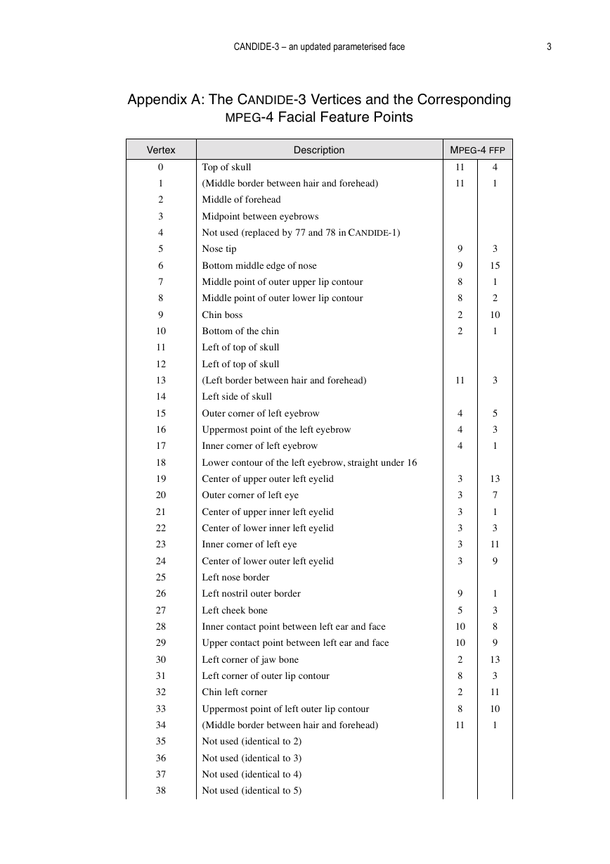
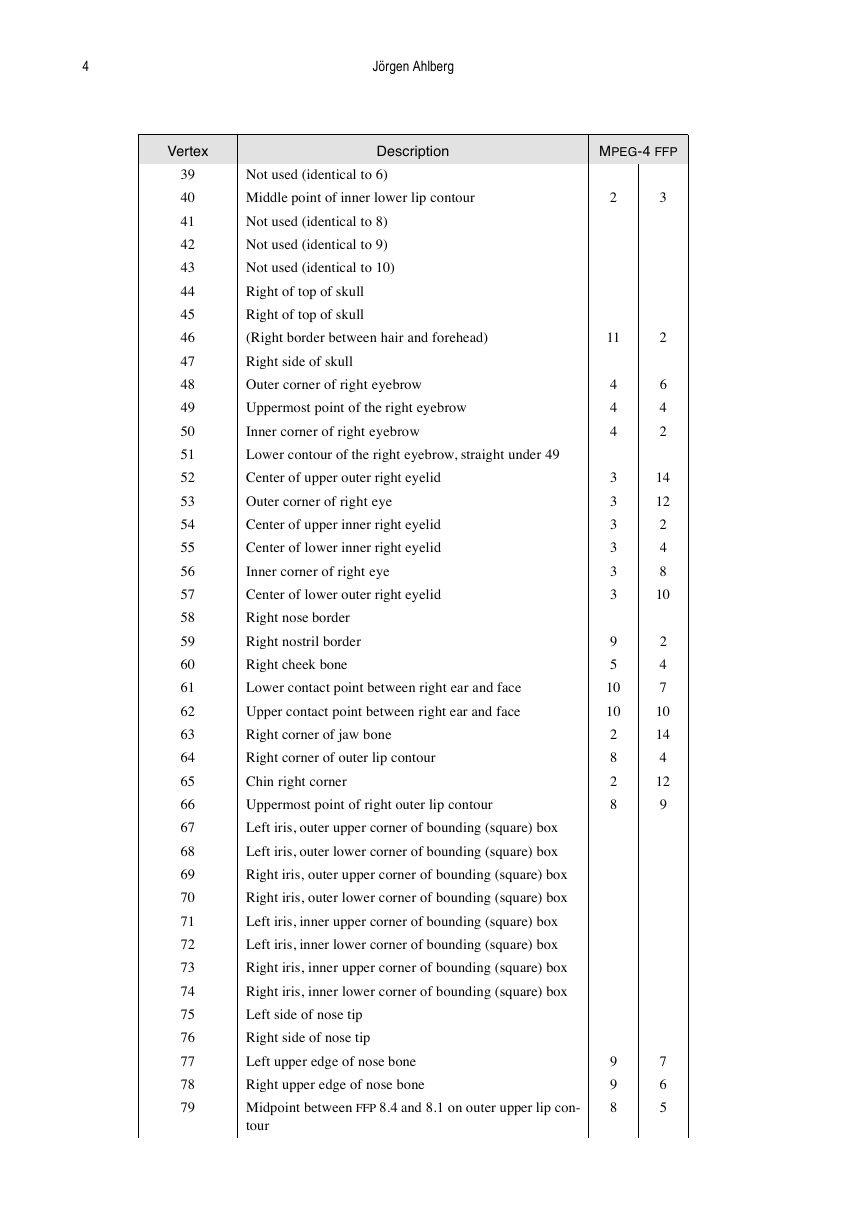
All the FFPs and all the vertices are listed in
Appendix A.
6.2. The FAP Units
The FAP units (FAPUs) are the units in which
the motion of the feature points due to FAPs are
measured. Except for the angular unit (AU),
they are represented by 1024:ths of the FAPUs.
For example, FAP 53 (stretch_l_cornerlip_o),
moves FFP 8.3 to the left, and the corrsponding
FAPU is MW (Motuh Width) [9]. Thus, setting
FAP 53 to 256 would move FFP 8.3 256/
1024 = 0.25 MW to the left.
In CANDIDE-3, that would mean moving ver-
tex 31 (which, according to Appendix A, corre-
sponds to FFP 8.3) to the left. The FAPU MW is
calculated as the difference of the x-coordinates
of vertex 31 and vertex 64 (see Table 2 below),
when the face is in neutral position (as defined
in [9]).
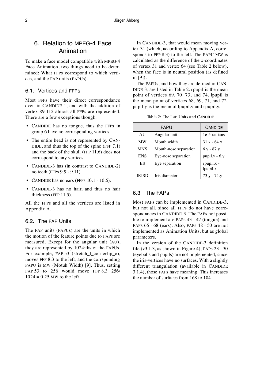
The FAPUs, and how they are defined in CAN-
DIDE-3, are listed in Table 2. rpupil is the mean
point of vertices 69, 70, 73, and 74. lpupil is
the mean point of vertices 68, 69, 71, and 72.
pupil.y is the mean of lpupil.y and rpupil.y.
Table 2: The FAP Units and CANDIDE
FAPU
AU
Angular unit
MW Mouth width
MNS Mouth-nose separation
ENS
ES
Eye-nose separation
Eye separation
IRISD
Iris diameter
CANDIDE
1e-5 radians
31.x - 64.x
6.y - 87.y
pupil.y - 6.y
rpupil.x -
lpupil.x
73.y - 74.y
6.3. The FAPs
Most FAPs can be implemented in CANDIDE-3,
but not all, since all FFPs do not have corre-
spondances in CANDIDE-3. The FAPs not possi-
ble to implement are FAPs 43 - 47 (tongue) and
FAPs 65 - 68 (ears). Also, FAPs 48 - 50 are not
implemented as Animation Units, but as global
parameters.
In the version of the CANDIDE-3 definition
file (v3.1.3, as shown in Figure 4), FAPs 23 - 30
(eyeballs and pupils) are not implemented, since
the iris-vertices have no surfaces. With a slightly
different triangulation (available in CANDIDE
3.1.4), those FAPs have meaning. This increases
the number of surfaces from 168 to 184.
�
CANDIDE-3 – an updated parameterised face
3
Appendix A: The CANDIDE-3 Vertices and the Corresponding
MPEG-4 Facial Feature Points
Vertex
Description
0
1
2
3
4
5
6
7
8
9
10
11
12
13
14
15
16
17
18
19
20
21
22
23
24
25
26
27
28
29
30
31
32
33
34
35
36
37
38
Top of skull
(Middle border between hair and forehead)
Middle of forehead
Midpoint between eyebrows
Not used (replaced by 77 and 78 in CANDIDE-1)
Nose tip
Bottom middle edge of nose
Middle point of outer upper lip contour
Middle point of outer lower lip contour
Chin boss
Bottom of the chin
Left of top of skull
Left of top of skull
(Left border between hair and forehead)
Left side of skull
Outer corner of left eyebrow
Uppermost point of the left eyebrow
Inner corner of left eyebrow
Lower contour of the left eyebrow, straight under 16
Center of upper outer left eyelid
Outer corner of left eye
Center of upper inner left eyelid
Center of lower inner left eyelid
Inner corner of left eye
Center of lower outer left eyelid
Left nose border
Left nostril outer border
Left cheek bone
Inner contact point between left ear and face
Upper contact point between left ear and face
Left corner of jaw bone
Left corner of outer lip contour
Chin left corner
Uppermost point of left outer lip contour
(Middle border between hair and forehead)
Not used (identical to 2)
Not used (identical to 3)
Not used (identical to 4)
Not used (identical to 5)
MPEG-4 FFP
11
11
4
1
9
9
8
8
2
2
11
4
4
4
3
3
3
3
3
3
9
5
10
10
2
8
2
8
11
3
15
1
2
10
1
3
5
3
1
13
7
1
3
11
9
1
3
8
9
13
3
11
10
1
�
4
Jörgen Ahlberg
Vertex
Description
MPEG-4 FFP
39
40
41
42
43
44
45
46
47
48
49
50
51
52
53
54
55
56
57
58
59
60
61
62
63
64
65
66
67
68
69
70
71
72
73
74
75
76
77
78
79
Not used (identical to 6)
Middle point of inner lower lip contour
Not used (identical to 8)
Not used (identical to 9)
Not used (identical to 10)
Right of top of skull
Right of top of skull
(Right border between hair and forehead)
Right side of skull
Outer corner of right eyebrow
Uppermost point of the right eyebrow
Inner corner of right eyebrow
Lower contour of the right eyebrow, straight under 49
Center of upper outer right eyelid
Outer corner of right eye
Center of upper inner right eyelid
Center of lower inner right eyelid
Inner corner of right eye
Center of lower outer right eyelid
Right nose border
Right nostril border
Right cheek bone
Lower contact point between right ear and face
Upper contact point between right ear and face
Right corner of jaw bone
Right corner of outer lip contour
Chin right corner
Uppermost point of right outer lip contour
Left iris, outer upper corner of bounding (square) box
Left iris, outer lower corner of bounding (square) box
Right iris, outer upper corner of bounding (square) box
Right iris, outer lower corner of bounding (square) box
Left iris, inner upper corner of bounding (square) box
Left iris, inner lower corner of bounding (square) box
Right iris, inner upper corner of bounding (square) box
Right iris, inner lower corner of bounding (square) box
Left side of nose tip
Right side of nose tip
Left upper edge of nose bone
Right upper edge of nose bone
Midpoint between FFP 8.4 and 8.1 on outer upper lip con-
tour
2
3
11
4
4
4
3
3
3
3
3
3
9
5
10
10
2
8
2
8
2
6
4
2
14
12
2
4
8
10
2
4
7
10
14
4
12
9
9
9
8
7
6
5
�


 2023年江西萍乡中考道德与法治真题及答案.doc
 2012年重庆南川中考生物真题及答案.doc
 2013年江西师范大学地理学综合及文艺理论基础考研真题.doc
 2020年四川甘孜小升初语文真题及答案I卷.doc
 2020年注册岩土工程师专业基础考试真题及答案.doc
 2023-2024学年福建省厦门市九年级上学期数学月考试题及答案.doc
 2021-2022学年辽宁省沈阳市大东区九年级上学期语文期末试题及答案.doc
 2022-2023学年北京东城区初三第一学期物理期末试卷及答案.doc
 2018上半年江西教师资格初中地理学科知识与教学能力真题及答案.doc
 2012年河北国家公务员申论考试真题及答案-省级.doc
 2020-2021学年江苏省扬州市江都区邵樊片九年级上学期数学第一次质量检测试题及答案.doc
 2022下半年黑龙江教师资格证中学综合素质真题及答案.doc