TA0356
Technical article
USB Type-C™ and Power Delivery DisplayPort Alternate Mode
Introduction
The USB Type-C and Power Delivery specifications allow platforms equipped with USB Type-C ports to negotiate power levels
up to 3 A at 5 V, 9 V and 15 V, and up to 5 A at 20 V, for a maximum 100 W power delivery.
Besides power negotiation, the specifications introduce Alternate Modes so USB Type-C hosts and devices can add
functionality like carrying high-speed data signals over USB Type-C connectors and cables; one of these modes manages the
DisplayPort video protocol.
The Video Electronics Standards Association (VESA®) and USB-IF released the “DisplayPort Alternate Mode on USB Type-C
Connector Standard” for devices equipped with Type-C connectors and compliant with USB Power Delivery specifications. It
defines how USB Type-C connectors and cables carry video signals in up to 4K resolution along SuperSpeed data lines and
other signals required by the DisplayPort protocol through secondary channels.
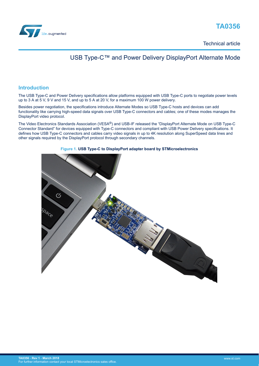
Figure 1. USB Type-C to DisplayPort adapter board by STMicroelectronics
TA0356 - Rev 1 - March 2018
For further information contact your local STMicroelectronics sales office.
www.st.com
�
TA0356
Power Delivery negotiation
1
Power Delivery negotiation
In the USB Type-C and Power Delivery specifications, power negotiation is accomplished between a power
source (provider) and a power sink (consumer) via message exchange.
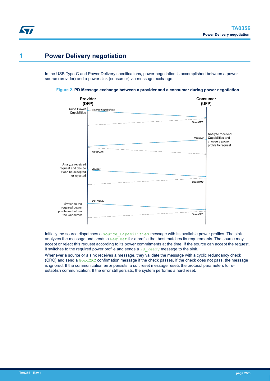
Figure 2. PD Message exchange between a provider and a consumer during power negotiation
Initially the source dispatches a Source_Capabilities message with its available power profiles. The sink
analyzes the message and sends a Request for a profile that best matches its requirements. The source may
accept or reject this request according to its power commitments at the time. If the source can accept the request,
it switches to the required power profile and sends a PS_Ready message to the sink.
Whenever a source or a sink receives a message, they validate the message with a cyclic redundancy check
(CRC) and send a GoodCRC confirmation message if the check passes. If the check does not pass, the message
is ignored. If the communication error persists, a soft reset message resets the protocol parameters to re-
establish communication. If the error still persists, the system performs a hard reset.
TA0356 - Rev 1
page 2/25
�
TA0356
DisplayPort Alternate Mode roles and negotiation
2
DisplayPort Alternate Mode roles and negotiation
The VESA DisplayPort Alternate Mode and USB Type-C Connector Standard specifications describe the
interactions between a video data source and a video data sink for entering or exiting Alternate Mode, as well as
the commands and rules to guarantee communication consistency between the two entities.
Alternate Mode negotiation cannot begin before the two partners (source and sink) reach an explicit contract
through the Power Delivery protocol, also defining the data role. Initially, the power source is the DFP (or host)
and the power sink is the UFP (or device).
The VESA Standard clearly describes data roles on the basis of port characteristics:
•
DFP_U: Downstream Facing Port (referred to as “DFP” in USB Type-C r1.3). Usually the ports on a host or
the ports on a hub to which devices are connected.
UFP_U: Upstream Facing Port (referred to as “UFP” in USB Type-C r1.3). The port on a device or a hub that
connects to a host or the DFP_U of a hub.
DFP_D: Downstream Facing Port (referred to “DFP” in DP Alt Mode standard v1.0a). Generally associated
with a DisplayPort source device, but may also be associated with a DisplayPort Branch device.
UFP_D: Upstream Facing Port (referred to “UFP” in DP Alt Mode standard v1.0a). Generally associated with
a DisplayPort sink device, but may also be associated with a DisplayPort Branch device.
•
•
•
The data roles (DFP_D and UFP_D) cannot change once the roles have been identified and the DisplayPort
protocol is running.
After the DFP and UFP are connected, the Type-C to DisplayPort Alternate Mode configuration sequence begins:
1.
The DFP (Source) detects the “Attach” event occurred of a UFP (Sink) on its Type-C connector, provides the
default voltage (5V) on its VBUS pin, and starts the power negotiation. The UFP selects one of the offered
Source Capabilities and reaches the explicit contract with the DFP.
The DFP requires for the list of supported modes to the UFP, using the structured vendor-defined messages
(VDM), and the UFP replies with the available modes supported by itself.
2.
3. Once the DFP selects the DP mode and then orders the UFP to reconfigure the pins of its type-C connector
to enter in the selected alternate mode, now the two entities respectively become DFP_D and UFP_D.
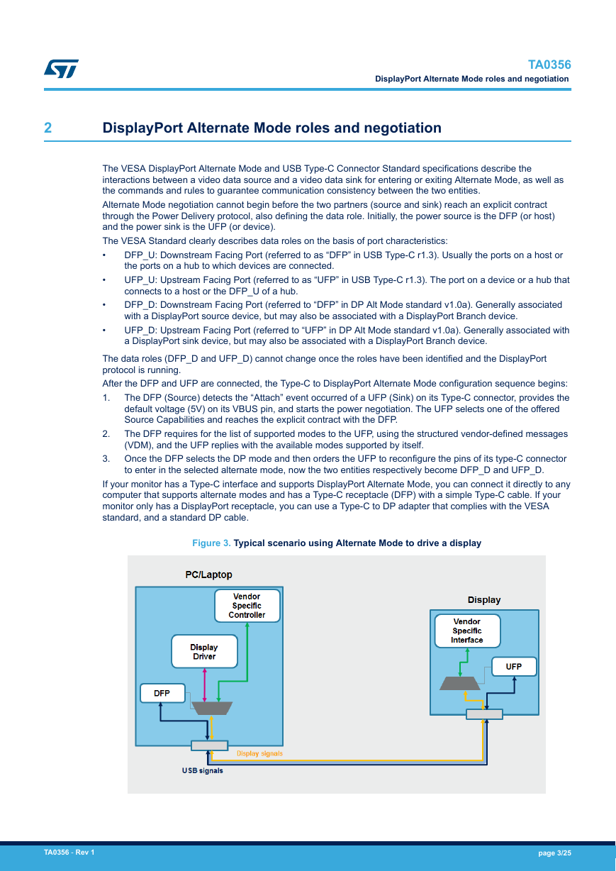
If your monitor has a Type-C interface and supports DisplayPort Alternate Mode, you can connect it directly to any
computer that supports alternate modes and has a Type-C receptacle (DFP) with a simple Type-C cable. If your
monitor only has a DisplayPort receptacle, you can use a Type-C to DP adapter that complies with the VESA
standard, and a standard DP cable.
Figure 3. Typical scenario using Alternate Mode to drive a display
TA0356 - Rev 1
page 3/25
�
TA0356
Type-C signaling configuration and functions description
3
Type-C signaling configuration and functions description
Alternate Mode reconfigures certain pins on a Type-C connector to support other protocols, like USB Type-C
connector pins assignment for the DisplayPort Alternate Mode. The different solutions supporting DP over USB
Type-C with specific connector pinouts and electrical wiring are listed in the VESA specification.
The 24-pin USB Type-C connector can be divided into seven functional types:
•
•
•
•
•
•
•
•
VBUS: four power pins allowing up to 20 V
CCx: two configuration channels for protocol communication
VCONN: supplies the cable configuration IC (on the receptacle, it is one of the CC pins)
SuperSpeed Lane1: with RX differential pair RX1p, RX1n and TX differential pair TX1p, TX1n
SuperSpeed Lane2: with RX differential pair RX2p, RX2n and TX differential pair TX2p, TX2n
SBU1,2: side band lines for alternate modes
Dp, Dn: USB 2.0 high speed signals
GND: four ground pins
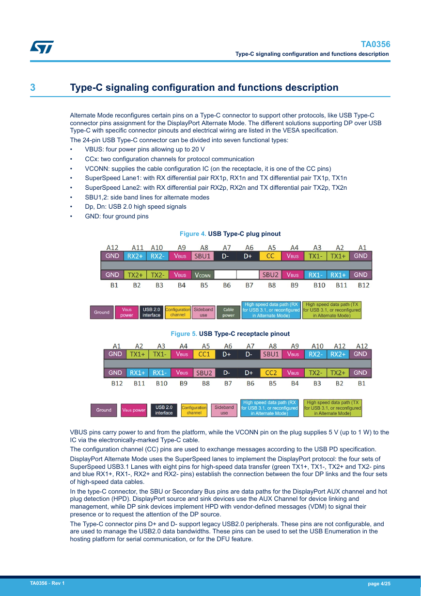
Figure 4. USB Type-C plug pinout
Figure 5. USB Type-C receptacle pinout
VBUS pins carry power to and from the platform, while the VCONN pin on the plug supplies 5 V (up to 1 W) to the
IC via the electronically-marked Type-C cable.
The configuration channel (CC) pins are used to exchange messages according to the USB PD specification.
DisplayPort Alternate Mode uses the SuperSpeed lanes to implement the DisplayPort protocol: the four sets of
SuperSpeed USB3.1 Lanes with eight pins for high-speed data transfer (green TX1+, TX1-, TX2+ and TX2- pins
and blue RX1+, RX1-, RX2+ and RX2- pins) establish the connection between the four DP links and the four sets
of high-speed data cables.
In the type-C connector, the SBU or Secondary Bus pins are data paths for the DisplayPort AUX channel and hot
plug detection (HPD). DisplayPort source and sink devices use the AUX Channel for device linking and
management, while DP sink devices implement HPD with vendor-defined messages (VDM) to signal their
presence or to request the attention of the DP source.
The Type-C connector pins D+ and D- support legacy USB2.0 peripherals. These pins are not configurable, and
are used to manage the USB2.0 data bandwidths. These pins can be used to set the USB Enumeration in the
hosting platform for serial communication, or for the DFU feature.
TA0356 - Rev 1
page 4/25
�
TA0356
Pin assignments
3.1
Pin assignments
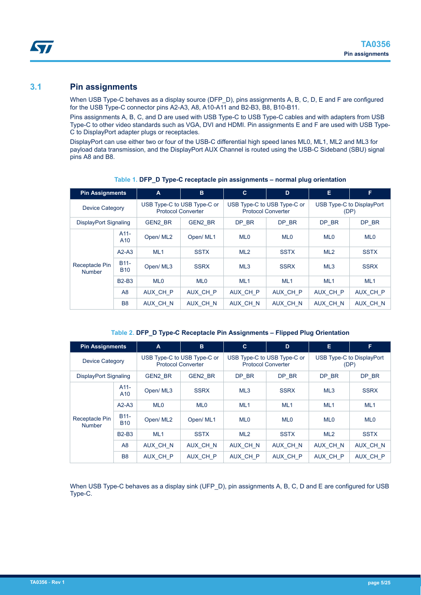
When USB Type-C behaves as a display source (DFP_D), pins assignments A, B, C, D, E and F are configured
for the USB Type-C connector pins A2-A3, A8, A10-A11 and B2-B3, B8, B10-B11.
Pins assignments A, B, C, and D are used with USB Type-C to USB Type-C cables and with adapters from USB
Type-C to other video standards such as VGA, DVI and HDMI. Pin assignments E and F are used with USB Type-
C to DisplayPort adapter plugs or receptacles.
DisplayPort can use either two or four of the USB-C differential high speed lanes ML0, ML1, ML2 and ML3 for
payload data transmission, and the DisplayPort AUX Channel is routed using the USB-C Sideband (SBU) signal
pins A8 and B8.
Table 1. DFP_D Type-C receptacle pin assignments – normal plug orientation
Pin Assignments
A
B
C
D
E
F
Device Category
USB Type-C to USB Type-C or
Protocol Converter
USB Type-C to USB Type-C or
Protocol Converter
USB Type-C to DisplayPort
(DP)
DisplayPort Signaling
A11-
A10
A2-A3
B11-
B10
B2-B3
Number
Receptacle Pin
GEN2_BR
GEN2_BR
DP_BR
DP_BR
DP_BR
DP_BR
Open/ ML2
Open/ ML1
ML1
Open/ ML3
ML0
SSTX
SSRX
ML0
ML0
ML2
ML3
ML1
ML0
SSTX
SSRX
ML1
ML0
ML2
ML3
ML1
ML0
SSTX
SSRX
ML1
A8
B8
AUX_CH_P
AUX_CH_N
AUX_CH_P
AUX_CH_N
AUX_CH_P
AUX_CH_N
AUX_CH_P
AUX_CH_N
AUX_CH_P
AUX_CH_N
AUX_CH_P
AUX_CH_N
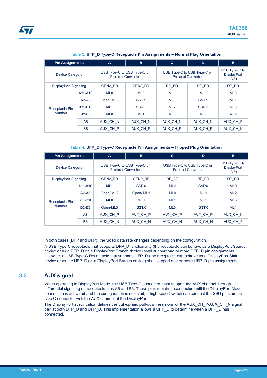
Table 2. DFP_D Type-C Receptacle Pin Assignments – Flipped Plug Orientation
Pin Assignments
A
B
C
D
E
F
Device Category
USB Type-C to USB Type-C or
Protocol Converter
USB Type-C to USB Type-C or
Protocol Converter
USB Type-C to DisplayPort
(DP)
GEN2_BR
GEN2_BR
DP_BR
DisplayPort Signaling
A11-
A10
A2-A3
B11-
B10
B2-B3
Number
Receptacle Pin
A8
B8
Open/ ML3
ML0
SSRX
ML0
Open/ ML2
Open/ ML1
ML1
AUX_CH_N
AUX_CH_P
SSTX
AUX_CH_N
AUX_CH_P
ML3
ML1
ML0
ML2
DP_BR
SSRX
ML1
ML0
SSTX
DP_BR
ML3
ML1
ML0
ML2
DP_BR
SSRX
ML1
ML0
SSTX
AUX_CH_N
AUX_CH_P
AUX_CH_N
AUX_CH_P
AUX_CH_N
AUX_CH_P
AUX_CH_N
AUX_CH_P
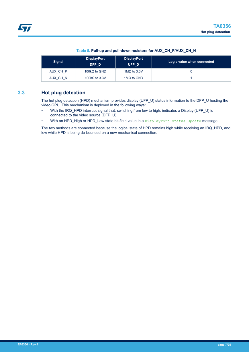
When USB Type-C behaves as a display sink (UFP_D), pin assignments A, B, C, D and E are configured for USB
Type-C.
TA0356 - Rev 1
page 5/25
�
Table 3. UFP_D Type-C Receptacle Pin Assignments – Normal Plug Orientation
Pin Assignments
A
B
C
D
E
TA0356
AUX signal
Device Category
USB Type-C to USB Type-C or
Protocol Converter
USB Type-C to USB Type-C or
Protocol Converter
DisplayPort Signaling
GEN2_BR
GEN2_BR
DP_BR
Receptacle Pin
Number
A11-A10
A2-A3
B11-B10
B2-B3
A8
B8
ML0
Open/ ML3
ML1
ML0
ML0
SSTX
SSRX
ML1
ML1
ML3
ML2
ML0
AUX_CH_N
AUX_CH_P
AUX_CH_N
AUX_CH_P
AUX_CH_N
AUX_CH_P
AUX_CH_N
AUX_CH_P
AUX_CH_P
AUX_CH_N
USB Type-C to
DisplayPort
(DP)
DP_BR
ML3
ML1
ML0
ML2
DP_BR
ML1
SSTX
SSRX
ML0
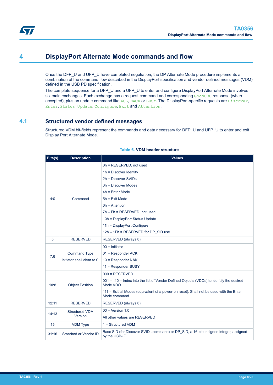
Table 4. UFP_D Type-C Receptacle Pin Assignments – Flipped Plug Orientation
Pin Assignments
A
B
C
D
E
Device Category
USB Type-C to USB Type-C or
Protocol Converter
USB Type-C to USB Type-C or
Protocol Converter
DisplayPort Signaling
GEN2_BR
Receptacle Pin
Number
A11-A10
A2-A3
B11-B10
B2-B3
A8
B8
ML1
ML0
Open/ML3
AUX_CH_P
AUX_CH_N
Open/ ML2
Open/ ML1
GEN2_BR
SSRX
ML0
SSTX
DP_BR
ML2
ML0
ML1
ML3
DP_BR
SSRX
ML0
ML1
SSTX
AUX_CH_P
AUX_CH_N
AUX_CH_P
AUX_CH_N
AUX_CH_P
AUX_CH_N
AUX_CH_N
AUX_CH_P
USB Type-C to
DisplayPort
(DP)
DP_BR
ML0
ML2
ML3
ML1
In both cases (DFP and UFP), the video data rate changes depending on the configuration.
A USB Type-C receptacle that supports DFP_D functionality (the receptacle can behave as a DisplayPort Source
device or as a DFP_D on a DisplayPort Branch device) shall support one or more DFP_D pin assignments.
Likewise, a USB Type-C Receptacle that supports UFP_D (the receptacle can behave as a DisplayPort Sink
device or as the UFP_D on a DisplayPort Branch device) shall support one or more UFP_D pin assignments.
3.2
AUX signal
When operating in DisplayPort Mode, the USB Type-C connector must support the AUX channel through
differential signaling on receptacle pins A8 and B8. These pins remain unconnected until the DisplayPort Mode
connection is activated and the configuration is selected; a high-speed switch can connect the SBU pins on the
type C connector with the AUX channel of the DisplayPort.
The DisplayPort specification defines the pull-up and pull-down resistors for the AUX_CH_P/AUX_CH_N signal
pair at both DFP_D and UFP_D. This implementation allows a UFP_D to determine when a DFP_D has
connected.
TA0356 - Rev 1
page 6/25
�
TA0356
Hot plug detection
Table 5. Pull-up and pull-down resistors for AUX_CH_P/AUX_CH_N
Signal
AUX_CH_P
AUX_CH_N
DisplayPort
DFP_D
100kΩ to GND
100kΩ to 3.3V
DisplayPort
UFP_D
1MΩ to 3.3V
1MΩ to GND
Logic value when connected
0
1
3.3
Hot plug detection
The hot plug detection (HPD) mechanism provides display (UFP_U) status information to the DFP_U hosting the
video GPU. This mechanism is deployed in the following ways:
•
With the IRQ_HPD interrupt signal that, switching from low to high, indicates a Display (UFP_U) is
connected to the video source (DFP_U).
With an HPD_High or HPD_Low state bit-field value in a DisplayPort Status Update message.
•
The two methods are connected because the logical state of HPD remains high while receiving an IRQ_HPD, and
low while HPD is being de-bounced on a new mechanical connection.
TA0356 - Rev 1
page 7/25
�
TA0356
DisplayPort Alternate Mode commands and flow
4
DisplayPort Alternate Mode commands and flow
Once the DFP_U and UFP_U have completed negotiation, the DP Alternate Mode procedure implements a
combination of the command flow described in the DisplayPort specification and vendor defined messages (VDM)
defined in the USB PD specification.
The complete sequence for a DFP_U and a UFP_U to enter and configure DisplayPort Alternate Mode involves
six main exchanges. Each exchange has a request command and corresponding GoodCRC response (when
accepted), plus an update command like ACK, NACK or BUSY. The DisplayPort-specific requests are Discover,
Enter, Status Update, Configure, Exit and Attention.
4.1
Structured vendor defined messages
Structured VDM bit-fields represent the commands and data necessary for DFP_U and UFP_U to enter and exit
Display Port Alternate Mode.
Bits(s)
Description
Values
Table 6. VDM header structure
4:0
Command
5
7:6
RESERVED
Command Type
Initiator shall clear to 0.
10:8
Object Position
0h = RESERVED, not used
1h = Discover Identity
2h = Discover SVIDs
3h = Discover Modes
4h = Enter Mode
5h = Exit Mode
6h = Attention
7h – Fh = RESERVED, not used
10h = DisplayPort Status Update
11h = DisplayPort Configure
12h – 1Fh = RESERVED for DP_SID use
RESERVED (always 0)
00 = Initiator
01 = Responder ACK
10 = Responder NAK
11 = Responder BUSY
000 = RESERVED
001 – 110 = Index into the list of Vendor Defined Objects (VDOs) to identify the desired
Mode VDO.
111 = Exit all Modes (equivalent of a power-on reset). Shall not be used with the Enter
Mode command.
RESERVED (always 0)
00 = Version 1.0
All other values are RESERVED
1 = Structured VDM
RESERVED
Structured VDM
Version
VDM Type
12:11
14:13
15
31:16
Standard or Vendor ID Base SID (for Discover SVIDs command) or DP_SID, a 16-bit unsigned integer, assigned
by the USB-IF.
TA0356 - Rev 1
page 8/25
�


 2023年江西萍乡中考道德与法治真题及答案.doc
 2012年重庆南川中考生物真题及答案.doc
 2013年江西师范大学地理学综合及文艺理论基础考研真题.doc
 2020年四川甘孜小升初语文真题及答案I卷.doc
 2020年注册岩土工程师专业基础考试真题及答案.doc
 2023-2024学年福建省厦门市九年级上学期数学月考试题及答案.doc
 2021-2022学年辽宁省沈阳市大东区九年级上学期语文期末试题及答案.doc
 2022-2023学年北京东城区初三第一学期物理期末试卷及答案.doc
 2018上半年江西教师资格初中地理学科知识与教学能力真题及答案.doc
 2012年河北国家公务员申论考试真题及答案-省级.doc
 2020-2021学年江苏省扬州市江都区邵樊片九年级上学期数学第一次质量检测试题及答案.doc
 2022下半年黑龙江教师资格证中学综合素质真题及答案.doc